Note : Les descriptions sont présentées dans la langue officielle dans laquelle elles ont été soumises.
20362~7
CORRUGATED CONSTRUCTION PALLET ASSEMBLY
Technical Field of the Invention
This invention pertains generally to pallets
and particularly to an improved pallet assembly made
predominantly of corrugated paper and with one or more
reinforced stringers.
Background of the Invention
Disposable pallets made of corrugated paper
are known in the art and have been commercially
available for a number of years. Such pallets are
disclosed, for example, in United States Patents No.
2,728,545, issued to Hermitage on December 27, 1955;
No. 3,683,822, issued to Roberts et al. on August 15,
1972; and No. 4,831,938, issued to Atterby et al. on May
23, 1989. Schmidtke United States Patent No. 4,792,325,
issued on December 20, 1988, provides a method and
machine for making a cardboard pallet. A particularly
desirable form of corrugated construction pallet, and a
method for manufacturing the same, are disclosed in
Quasnick United States Patent No. 4,867,074, issued
September 19, 1989.
To be satisfactory for their intended
purposes, it is of course necessary that any such pallet
exhibit an advantageous strength-to-weight ratio, and
also that it be capable of withstanding considerable
abuse, particularly under conditions that would
typically be encountered during commercial shipment of a
load thereupon. While prior art structures of this kind
have been found to be generally satisfactory, one area
of notable deficiency has resided in the levels of
lateral stability that they afford; specifically, the
load carried by a pallet tends to shift in transit, or
at least to impose forces thereupon that are of varying
magnitude and direction. Pallets that do not offer
adequate lateral stability will tend to fail, with the
likelihood thereof depending of course upon the mass of
2035217
2 23158-1645
the load, the conditions to which it is subjected in transit,
time factors, etc. The above-identified Quasnick patent
substantially advances the art in these regards, but it goes
without saying that the realization of still further
improvements would be highly desirable.
Suw~arY of the Invention
According to thls invention, an improved pallet
a~sembly comprises a plurality of stringer members fabricated
from web material and a multiplicity of elongated decking
members traversing said stringer members and being assembled
therewith adjacent a top side of the pallet assembly; each of a
plurality of said stringer members having indentations
extending upwardly thereinto and transversely therethrough,
said indentations defining a neck portion at a bottom side of
each of said stringer members having said indentations; said
assembly comprising a plurality of hollow, tubular reinforcing
pieces, each of said reinforcing pieces being inserted upwardly
into said indentations in an associated one of sald stringer
members having said indentations with said neck portion thereof
extending downwardly thereinto, said reinforcing pieces and
said stringer members associated therewith being securely and
tightly interengaged with one another; opposite sidewall
portions of each of said reinforcing pieces being axially and
transversely slotted so as to define slots in said sidewall
portions, portions of the associated one of said stringer
members disposed upwardly of said neck portion thereof being
engaged within the slots of each of said reinforcing pieces;
said stringer members having bottom surfaces disposed
substantially on a common plane and said reinforcing pieces
having bottom surfaces disposed substantially on said plane.
The reinforcing pieces will most advantageously be
cylindrical, and in a preferred embodiment the stringer members
2036217
3 23158-1645
and the reinforcing pieces will be frictionally interengaged,
with the pallet assembly being devoid of adhesives and
mechanical fasteners securing those components together.
The plies of web material of which the stringer
members are comprised will normally be oriented substantially
parallel to the axis of the associated reinforcing piece. Both
the stringer members and also the decking members will usually
be of one-piece, corrugated paper construction, and most
desirably the reinforcing pieces will be made of paper as well.
Tightly wound paper tubing, such as that used for cores for
paper rolls, is a suitable material for such pieces.
Other objects of the invention are attained by the
provision of a method for manufacturing a reinforced pallet
assembly constructed as hereinabove set forth. The steps
constituting the improvement thereof include forming upwardly
and transversely extending indentations in each of a plurality
of said stringer members to define a neck portion at the bottom
side thereof, and inserting a hollow tubular reinforcing piece
upwardly into said indentations of an associated one of said
stringer members with said neck portion thereof extending
downwardly thereinto, so as to effect secure and tight
interengagement therebetween.
The method will preferably include an additional step
in which opposite sidewall portions of each reinforcing piece
are axially and transversely slotted before assembly with the
associated stringer member. Most desirably, interengagement
between the components will be effected by frictional means
alone.
Brief Description of the Drawings
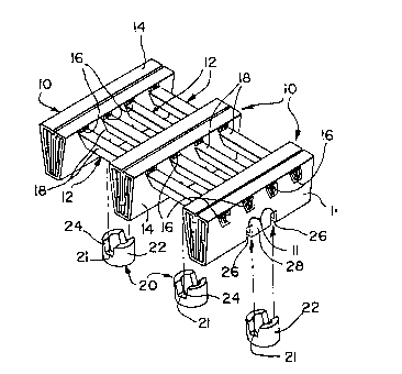
Figure 1 is an exploded perspective view of a pallet
assembly embodying the present invention.
`-~ 2036217
3a 23158-1645
Figure 2 is an elevational view of a cylindrical
reinforcing piece utilized in the assembly of Figure 1, drawn
to an enlarged scale;
Figure 3 is a plan view of the reinforcing piece of
Figure 2;
Figure 4 is a fragmentary side elevational view of
the pallet assem~ly of Figure 1, shown in partial section and
drawn to the scale of Figures 2 and 3;
~,
20~621~
- 4 -
Figure 5 is a fragmentary bottom view of the
pallet assembly; and
Figure 6 is a vertical sectional view of the
assembly, taken along lines 6-6 of Figure 4.
Detailed Description of the Illustrated Embodiment
Turning now in detail to the appended
drawings, therein illustrated is a pallet assembly
embodying the present invention and consisting of three
stringer members, generally designated by the numeral
10, and four transversely ext~n~;ng decking members 12,
assembled therewith. As can best be seen from Figures
4-6, the stringer and decking members are fabricated
from single pieces of multiple-ply web material (e.g.,
275 pound, C-flute corrugated paper) folded to provide
elongated structures of generally trapezoidal cross-
section, symmetrical about their vertical, longitudinal
center lines. These components are similar to those
that are described more fully in the above-identified
Quasnick Patent No. 4,867,074, albeit that (as
substantiated by the illustrated embodiment hereof) the
improved stringer construction described therein need
not necessarily be employed in the instant assembly. As
can be seen, each stringer member 10 is formed with four
transverse passages 16 at a level proximate the top side
of the pallet assembly, to accommodate and tightly
engage the decking members 12.
Tubular reinforcing pieces, generally
designated by the numeral 20, are assembled with the
stringer members 10. Tightly wound paper tubing, such
as that used for cores for paper rolls, is a suitable
material for the pieces 20. Another dense, rigid and
strong material may be alternatively used. Each piece
20 consists of a cylindrical sidewall 22, which defines
an axis, and opposite portions of which are slotted
axially and transversely, as at 24. The bottom side
portion of each stringer member 10 is correspondingly
-- 2036217
indented inwardly and transveræely, as at 26, creating a
short neck portion 28 therebetween. The reinforcing
piece 20 is assembled with the associated stringer
member 10 by inserting the neck portion 28 into the bore
30 thereof, ultimately bringing the corresponding
shoulder surface 11 and 21 thereon into abutment to
thereby firmly seat the reinforcing piece upon the
stringer member. It will be noted that in the fully
inserted condition the bottom surfaces 32 and 34 of the
stringer members and reinforcing pieces, respectively,
are disposed on a common, normally horizontal plane. It
will also be noted that the reinforcing pieces 20 are
held tightly and securely in place merely by frictional
force, without use of any adhesive or fastener, albeit
that such supplemental means, or mec-h~nically
interlocking elements, may be employed if so desired.
Although the preferred form of stringer
members, decking members and reinforcing pieces are
illustrated, it will be appreciated that each such
component may take any of a variety of different
configurations and constructions without departing from
the scope of the instant invention. For example,
virtually any of the structures described in the above-
identified prior art patents may be employed in the
practices hereof. It is important, however, that
sidewall elements of the reinforcing pieces extend along
the outer surfaces of the stringer members with which
they are associated; they provide lateral support and
assistance in maintaining the integrity of the stringer
member, thus contributing significantly to the ability
of the assembly to withstand lateral forces and shifting
load conditions, and thereby helping to minimize damage
and the likelihood of premature failure of the pallet.
It will be appreciated that the pallet
assembly shown in Figure 1 is merely exemplary, and that
in many instances a greater (or perhaps lesser) number
2036Z17
of stringer members and deck~ng members will be
employed, dep~nA;ng primarily upon load factors and the
surface area that is to be presented on the top side of
the pallet. For example, the assembly may utilize ten
A~cking members and three stringer members, to provide a
~upporting surface area measuring 48 x 40 inches, as is
conventional. Furthermore, the number and arrangement
of reinforcing pieces may vary from that illustrated,
and typically three, six or nine of them will be
employed. Needless to say, each stringer member may
carry more than a single reinforcing piece, such as, for
example, by providing one closer to each opposite end
rather than in a centralized location, as illustrated.
Also, it is possible to omit such reinforcing pieces
lS from selected stringer members, such as the middle
stringer member of the illustrated pallet. Finally,
although paper will normally constitute the preferred
materialof construction of all components of the
assembly, to afford optimal recycle characteristics and
other benefits, plastic and other materials may be
substituted in appropriate circumstances.
Thus, it can be seen that the present
invention provides a novel disposable pallet assembly,
made (except for the reinforcing pieces) of corrugated
paper or like material, which exhibits an advantageous
strength-to-weight ratio coupled with a high degree of
lateral stability and resistance to collapse under
shifting load conditions. The invention also provides a
novel method for producing such a pallet assembly
(usually corrugated for the stringer and dec~ing
members, and of a dense, rigid and ~L~G~.~ form for the
reinforcing pieces), and the method and assembly hereof
are highly advantageous from the standpoints of
simplicity, cost and production facility.
3S