Note : Les descriptions sont présentées dans la langue officielle dans laquelle elles ont été soumises.
2Q3~62
CONTINUOUS PROCESS FOR PRODUCING
ADDUCTED EPM OR EPD~ OIL SOLUTION
The pre~nt invention relates to a continuous pro~ess for
the production of adducted, or capped, derivatized 2thylene-
propylene copolymer or te~polymer (EP~ or ~PD~) oil solution.
Engine motor lubricant formulations are conventionally
based upon dilute solutions of synthetic ela3tomers in oil. The
addition of low molecular weight polymer constituents to the oil
provides an improvement in ~he viscosity index (VI) over the oil
itself, such that the desired lubricant viscosity is achieved and
maintained over the operating temperature range of the motor.
Polymeric visco~ity index lmprovers for lubricants are
known in the art. For instance, Vnited States Patent No. 4,161,452
de3cribes the grafting in solu~ion of diacid or a~hydride
functional monomer~ to ethylene copolymers with recovery of ~he
grafted product in solid form, to provide a viscosity index
improv r. Accordin~ to that patent, the grafted batch product may
then be inco~porated into a~ oil system to provide the desired VI
improvement.
United States Paten~ No. 4,357,250 discloses the use in
lubricants, as a dispersan~ and viscosity modifier, of derivatized
ethylene copolymers preparad by Ene reactions.
203~2
The reaction product of maleic anhydride with a saturated
ethylene propylene rubber of low molecular weight has been employed
to produce a low molecular weight oil ~isco~ity index Lmprover,
according to United States Patent No. 4,670,515.
The continuous gra~ting of e~hylene copolymers and
terpolymers in solution with monomers to produce an oil solution
including a dispersant slefin copolymer tha~ also functions as a
viscosity index Lmprover i taught in United States Patent No.
4,340,689.
None of the foregoing patents, however, de~cribes a
continuous process for producing an adducted derivatized ethylene-
propylene copolymer or terpolymer oil solution. A continuous
process results in lower production costs over batch processes for
producing sLmilar products, and further provides a more consi tent
product over tLme. In addition, a continuous process is more
energy efficient than alternative processes. It also has the
environmental advantage of generating no waste streams, ~ince raw
materials and intermediate species are either recovered or
incorporated into the end produtO
~ oxeover, an adducted product is particularly desirable
for providing long ~erm stabiliza~ion of the oil solution, in that
203~8Ç~2
oxidation of the oil solution is reduced or eliminated by the
presence of an adducted species having antioxidant properties.
SUMMARY OF THE I~ENTION
The present invention provides a continuous process
having the foregoing advantageous characteristics. According to
~he present invention, a continuous process for producing an
adducted derivatized EPN or EPDM oil solution i5 provided,
comprising the continuous sequence of interpol~merizing in solution
monomers of ethylene and an olefinic hydrocarbon having from 3 to
16 carbon atoms, and in some cases a polyene monomer, to produce
a polymer product, concentrating the polymer product in the
solution, grafting the polymer with a grafting monomer selected
from the group consis~ing of an organic acid or anhydride,
preparing an oil solution of the grafted reac~ion productsr mixing
the oil solution with an antioxidant polyamine composi~ion in the
presence of an aliphati or phenolic alcoho~ ethoxylate solvent,
and holdin~ the mixture for a sufficient time and at a temperature
sufficient to permit the forma~ion of an imide adduct between ~he
grafted polymer and the polyamine.
The invention is further directed ~o the adducted product
formed by this process.
2~3~g~2
Thus it is an object of the presen~ invention to provide
a continuous proces for producing a stable EP~ or ERDM oil
solution having the advan~age o lower production cost~ associated
with the continuous process.
Another ob~ect of the invention is to provide such a
proce~s wherein no waste stream~ are generated by the process,
thereby producing no deleterious environmental effects.
Still another object of the invention is to provide such
r ~ 90 ~C ~ Z - ~CI
a process whereby~ener~y costs associated wi~h the process are
produced.
Yet another ob~ect of the invention is to produce such
a produot wherein the formation of the adduct produces an oxida~ion
resistant oil solution stable over reasonably long durations.
A further object of the invention i5 to provide such a
product wherein the adduc~ formation results in both dispsrsant and
antioxidant properties.
.~
~ hese and other objects and advantages of the pr~sent
invention will become apparent from the detailed description of the
invention provided below.
2~36~,~2
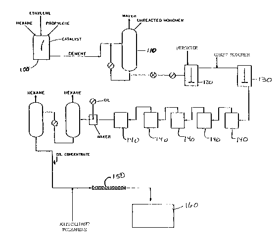
BRIEF DESCRIPTION O~F THE DRAWING
FIG. 1 is a process flow diagram illustrating graphically
the steps of ~he process of tha present invention.
FIG. 2 is a graph showing the variation in weight percent
of stored polyamine over tLme during holding o~ the adducted EPM
or EPDM oil solution made according to the present invention.
DETAILED DESCRIPTI~N OF THE INVENTION
0 ~c ~ z ~ 0
c~~ ~c~s l n~.~'p~ tcj ~ z ~ J
The,~proces~ of the present inven~ion ~*v~e~ a number
of steps including the formation of the derivati%ed EPM or EPDM
along with the steps producing the adducted EPM or EPDM oil
solution, as shown in FIG. 1. As disclosed in Uni~ed States Patent
No. 4,340,689 ("the ~689 patent"), incorporated by reference
herein, ~he continuous grafting of ethylene copolymers in solution
with monomers to produce an oil solution including a dispersant
olefin copolymer that also functions as a viscosity index Lmprover.
The preferred EP~ copolymer is produced by interpolymeriæation in
solution of monomers of e~hylene and one or more higher mono-
olefins having fxom 3 to 16 carbon atoms, preferably propylene.
The reaction is carried out in solu~ion in the prasence of
2~3~2
Ziegler catalyst, e.q., a vanadium compound activated by an alkyl
aluminum chloride.
If EPDM is to be produced, one or more polyenes are also
added to the interpolymerization reaction mixture described above.
Suitable polyene monomers may be selected from branched chain
monomers, straight or branchsd chain polyene or cyclic polysnes
containing 4 to 20 carbon atoms and preferably 5 to 10 carbon atoms
and two carbon-carbon double b~nds. Useful polyenes include the
alkylidene norbox~enes, andspecifically2-ethylidene-5-norbornene.
The EPM or EPDM polymerization is carried out on a
continuous basis in an agitated first reaction ~essel 100 into
which monomer, catalyst and polymerization accelerator~ have been
continuously supplied, and fxom which reaction products are
continuously withdrawn. A cement of the polymerized reaction
produc~s is then preparPd by concentrating the reaction products
in a second vessel llO. Such concentration is desirable for
increasing efficiency of a subsequent grafting reaction, and for
reducing the likelihood of producing unwanted byproducts during the
grafting reaction.
The cemen~ thus produced is advanced to a mixer or mixers
120, 130 where it is mixed with a grafting monomer and a peroxide
cata~yst to achieve a desired grafting reaction. The peroxide
:
2 ~ 2
catalyst is one having a half life (Tl~2) of 10-20 minutes at the
reaction vessel temperature of 250-350F, and is preferably one
having Tl,2 of 12-17 minutes at 300-325F. Examples of such
catalysts include DIcuP~ (Hercules, Inc.), which is dicumyl
peroxide, and VAROg~ (R.T. Vanderbilt Co.~, which is 2,5-dLmethyl-
2,5-di(tertbutyl peroxy) hexane.
The resulting mixture is then pa~sed from the first
reaction vessel to a third reaction vess21 140, which may
preferably be a plurality of reactors connected in eries for
continuous operation as shown in FIG. 1. After reaction, solvent
is removed according ~o steps set forth in the ~689 patent, and the
oil solution i5 made.
With respect to the present invention, the process of the
'689 patent is used to graft an organic acid or anhydride to the
EPM copolymer having the generalized structure
C--X
Y~
Y 11~
R--C -X
-- 7 ~
2~3~2
in which R is an alkylene group having 0-4 carbon atoms; ~ is
hydrogen or a branched or straight chain alkyl group, a halogen
group such as chlorine, bromine or iodine, or a heterocyclic or
other organic group having 1-12 carbon atoms; and X is a hydroxy,
alkoxy or arylo~y group, but at least one ~ group is hy~roxy. The
structure is such as to permit formation of an imide upon reaction
with the amine composition described below. For EP~, the grafted
group is preferably maleic anhydride.
The amount of graft will vary depending upon the
particular characteristics desired in the final product. In the
preferred embodiment, an 2mount of 0.5-1.5 weight percent maleic
anhydride in the grafted EPM is employed. The oil solution
production process described above and disclosed in ~he '689 patent
is adjusted to produce an effluent end stream composed of between
10 and 20 percent by weight grafted EPM and about 80~90 weight
percent paraffinic oil.
In the present in~ention, a second stream is added to
this end stream, consisting of an antioxidant polyamine
composition, R-(NH2)n,' in which n is at least two, in organic
solution. ~ffectiYe composi~ions for the amine are such that a
first, or primary, amine group is separated from a secondary amine
group (or tertiary amine group, if more than two amine groups are
provided) by at least three or more carbon a~oms. Two effective
'~ 0 3 ~
antioxidant polyamine groups are N,N-dimethyl, 1,3-diaminopropane
and N-phenyl, 1,4-phenylene diamine (NPPDA), the lat~er of which
is preferred. The amina composition is provided in stoichiometric
quantities based upon the amount of graf~ed monomer present in ~he
EPM or EPD~ oil solution, so that ~he grafted func~ionality is
completely adducted by the amine and the organic solvent. In the
preferred embodiment, this ratio will be O.6-1.2 amine~con~aining
molecules per grafted anhydride group.
The organic solvent employed is selected to be compatible
with ~he compositionq in the first stream and consists of the
family of aliphatic or phenolic alcohol ethoxylates as shown by
the structure below:
R~H2~H2~C~2--CH2--~
wherein x is a number from 1-10, and R is either an aliphatic group
ha~ing from 7 to 20 carbons or an aryl group such as phenyl and
substituted derivatives thereof, the substitution being an alkyl
group having from three to 20 carbons. Useful examples include
SURFONIC~ N-~O or N-60 (Texaco, Inc.), which are the reaction
products of nonyl phenol with ethylene oxide, and SU~FONIC~ L46~7,
which is the reaction product of C12-C18 aliphatic alcohols with
ethylene oxide. Other organic solvents useful in the practice of
this invention include the reaction produc~s of other alkyl phenols
and or C7-C20 aliphatic alcohols with ethylene oxide.
The first and second streams are fed together into a
mixer 150, e.~., a static mixer, of sufficient size and mixing
capacity to permit complete mixing of ~he two streams. Thorough
mixing permits formation of an adduct between the amine functional
group and the anhydride. Thus, the adduct formed is an Lmide:
O O
l 11 1 11
C C:~ C~
¦¦ ~0 + ~R NH2 ¦¦ N--R + H20 ( I )
l 11 1 11
O O
or an acid amide:
O Organic I O
l ll Solvent l ll
C--~C~ R' C----C--NH--R
ll O + R--NH2 > ll + H20 (II)
C--C'' C~--R '
l 11 1 11
O O
in which the reactant R-NH2 a~ shown is the antioxidant polyamine
composition described above.
It is also hypothesized that, in the first stream, there
will be present small quantities of maleic anhydride oligomer
-- 10 --
2~3~
formed from excess maleic anhydride monomer during the grafting
reaction. This specie~ is also adducted according ~o reaction
(III), with the resulting product belie~ed to contribute to ~he
chelating/disper3ant performance of the oil solution.
O O Organic
~ Solvent -
C--C--C--C R'
O~ ¦ ¦ ~ O + ~ R-- NH2 ~ >
C~ ~
Il l l 11
O l l O
~I O O
1 11 11 .
R- N--C--C--C--C
l l N ~ R + H2O (III~
R'--C--C C--C
Il l l 11
O l l O
The resultant adducted mixture is advanced to a holding
tank 160, where it is preferably held at adduct forming
temperatures to drive reaction (I) and maintain the presence of
adduc~ imide in the solution. Such temperatures are in the range
of 120-350~, with the range of 300-350F being preferred.
It has also been determined that a greater capping
efficiency results when the capping reaction occurs under a
nitrogen atmosphere, rather than a vacuum. Thus, the mixed product
is preferably held under a nitrogen atmosphere to provide increased
capping efficiency.
~3~8~2
It has been observed that holding the adduc~ed mixture
at the adduct fo~ming reaction temperature resultq in an increasing
amount of adducted EPM or EPDM. This is shown by the data se~
forth in Table I. FIG. 2 is a theoretical graph showing the
variation in weight percent of stored polyamine (NPPDA) over time
during holding of the adducted EPM or EPDM oil solution made
according to the present invention. Table II shows similar data
for several different samples of adducted derivatized EP~ or EPD~.
TABLE I
~O~DING
TI~E NPPDA
( hr! (wt96 !
0.25 1.36
0.75 1.39
1.25 1.39
1.75 1.47
2.25 1.58
2.75 1.61
3.75 1.60
4.75 1.62
5.75 _ _ 1.61
TheoreeLc~l Mr~x~ 1.73 wt~.
- 12 -
~3~862
,
TABLE II
Total ~ Analyzed NPPDA (wt %)~
Target
NPPDA Reaction TLme (hours)
L_ 3 6_ 24 ?2 Final
6.8 Bound 1.31 --- 1.92 2.11
Total 2.74 -~~ 9.54 9.39
6.8 Bound 1.63~ 1.73 1.82 1.95 -~
Total 6.677.03 7.67 7.85
4.5 Bound 1.351.39 1.65 1.59 ----
Total 4.454.52 4.55 4.60 ----
4.5 Bound 1.171.27 1.39 1.49 1.48
Total 4.594.49 4.47 4.23 4.56
4.5 Bound 1.111.26 1.36 1.63 1.50
Total 3.643.99 4.28 4.18 4.40
4.5 Bound 1.231.28 1.44 1.60 1.55
Total 4.975.05 5.12 5.05 5.02
The advantages of the continuous cappiny process of the
present invention as applied in a continuous graft cement
production system, as compared to a batch capping process, are
shown in Table III, which includes comparative data for batch
capped oil solution a~d ~ontinuously capped oil solution. In the
batch capping process, the cement, oil and amin solution are
combined in a sealed vessel, and the hexane stripped off with
stirring by raising the temperature of ~he mixtuxe to about 370F
under a vacuum.
. .,
2 Q ~ 2
The data shown in Table III illustrates the superiority
of products produced according to the present in~ention, in which
the cement is produced continuously and capped continuously, as
compared to products wherein either the cemen~ produc~ion or the
capping process is a batch process, or both.
TABLE III
Graft Capping NPPDA/Total Bound Engine Test
Cement Process MAH Ratio NPPDA Performance
Type ~y~ (molar! ~wt ~ Sequence VE
Batch Batch 0.43 0.47 Failed
Batch ~atch 0.55 1.28 ~ood
Batch Continuous 0.55 1.17 Excellent
Batch Continuous l.0 1.60 Not tested
Continuous ~atch 0.48 0.83 Not tested
Continuous Continuous 1.1 l.9S Excellent
Continuous Continuous 0.74 1.65 Excellent
Continuous Continuous 0.77 1.48 Excellent
The effects of holding under a nitrogen atmosphere as
compared to holding under a vacuum are illustrated by the data
shown in Table I~. There, it is shown that substantially higher
efficiencies of capping are produced as a resul~ of adduct
formation in holding under a nitrogen a~mosphere as compared to
holding and adduct formation under a vacuum, whexe the composition
is formed according to the present invention.
- 14 -
2~3~
TABLE IV
Capping Efficiencies Under Different Atmospheres
Reaction Total Bound ~heoretical Capping
TLme (hrs)_ AtmosPhere NPPDA NPPDA Bound NPPDA __Eficiency
8 Nitrogen 1.67 0.74 1.24 0.60
17 Nitrogen 1.80 0.65 1.24 0.52
17 Nitrogen 2.28 1.17 1.24 0.94
Nitrogen - 2.89 1.32 1.24 1.06
18 Nitrogen 2.99 0.92 1.24 0.74
18 Nitrogen 2.84 0.96 1.24 0.77
18 Nitrogen 2.27 1.16 1.24 0.94
8 Vacuum 1.66 0.60 1.24 0.48
8 Vacuum 1.80 0.71 1.35 0.53
8 Vacuu~ 1.47 0.51 1.20 0.43
.. . ... . . .. .. ... .
The present inYention has been described with respect to
certain embodimen~s and conditions, which are not meant to and
should not be cons~rued ~o limit the invention. Those skilled in
~he art will understand ~hat variations from the embodim nts and
conditions described herein may be made without departing from the
in~en~ion as olaLmed in the appended claLms.
- 15 -