Sélection de la langue

Search

Sommaire du brevet 2037367 

Énoncé de désistement de responsabilité concernant l'information provenant de tiers

Une partie des informations de ce site Web a été fournie par des sources externes. Le gouvernement du Canada n'assume aucune responsabilité concernant la précision, l'actualité ou la fiabilité des informations fournies par les sources externes. Les utilisateurs qui désirent employer cette information devraient consulter directement la source des informations. Le contenu fourni par les sources externes n'est pas assujetti aux exigences sur les langues officielles, la protection des renseignements personnels et l'accessibilité.

Disponibilité de l'Abrégé et des Revendications

L'apparition de différences dans le texte et l'image des Revendications et de l'Abrégé dépend du moment auquel le document est publié. Les textes des Revendications et de l'Abrégé sont affichés :

  • lorsque la demande peut être examinée par le public;
  • lorsque le brevet est émis (délivrance).
(12) Demande de brevet: (11) CA 2037367
(54) Titre français: BOGIE FERROVIAIRE A GLISSOIR DE CAISSE REGLABLE EN HAUTEUR
(54) Titre anglais: RAILWAY TRUCK ASSEMBLY WITH SIDE BEARING HEIGHT ADJUSTER
Statut: Réputée abandonnée et au-delà du délai pour le rétablissement - en attente de la réponse à l’avis de communication rejetée
Données bibliographiques
(51) Classification internationale des brevets (CIB):
  • B61F 03/00 (2006.01)
  • B61F 05/14 (2006.01)
(72) Inventeurs :
  • DUMOULIN, RAYMOND (Canada)
(73) Titulaires :
  • BOMBARDIER INC.
(71) Demandeurs :
  • BOMBARDIER INC. (Canada)
(74) Agent: SWABEY OGILVY RENAULT
(74) Co-agent:
(45) Délivré:
(22) Date de dépôt: 1991-02-28
(41) Mise à la disponibilité du public: 1991-10-28
Requête d'examen: 1997-10-02
Licence disponible: S.O.
Cédé au domaine public: S.O.
(25) Langue des documents déposés: Anglais

Traité de coopération en matière de brevets (PCT): Non

(30) Données de priorité de la demande:
Numéro de la demande Pays / territoire Date
515,417 (Etats-Unis d'Amérique) 1990-04-27

Abrégés

Abrégé anglais


RAILWAY TRUCK ASSEMBLY WITH
SIDE BEARING HEIGHT ADJUSTER
Abstract of the Disclosure
In a truck assembly for a railway vehicle wherein
the assembly has a truck frame defined by opposed side frame
sections and a transom section extending transversely
between the side frame sections and substantially at
mid-length thereof. A pair of wheels are supported between
opposed ends of the side frame sections. A truck bolster
assembly is supported above the transom for supporting a cab
thereon. The bolster assembly is retained in position
relative to the transom by a central pivot. The improvement
comprises side bearing height adjusting means which include
interchangeable bearing elements of different heights. The
bearing elements, one at a time, are selectively positioned
between the truck frame and the truck bolster assembly and
spaced from the central pivot on a respective side thereof.
The side bearing height adjusters have a bearing element
with a top friction support surface to permit horizontal
displacement of the bolster assembly about the central
pivot.
- 1 -

Revendications

Note : Les revendications sont présentées dans la langue officielle dans laquelle elles ont été soumises.


The embodiments of the invention in which an exclusive
property or privilege is claimed are defined as follows:
1. In a truck assembly for a railway vehicle, said
assembly having a truck frame defined by opposed side frame
sections and a transom section extending transversely
between said side frame sections substantially at mid-length
thereof, a pair of wheel assemblies supported between
opposed ends of said side frame sections, and a truck
bolster assembly supported above said transom for supporting
a cab thereon, said bolster assembly being retained in
position relative to said transom by a central pivot, the
improvement comprising side bearing height adjusting means
including interchangeable bearing elements of different
heights; said bearing elements, one at a time, being
selectively positioned between said truck frame and said
truck bolster assembly and spaced from said central pivot on
a respective side thereof, said side bearing height
adjusters having a bearing element with a top friction
support surface to restrain rotation of said bolster
assembly about said central pivot.
2. A truck assembly as claimed in claim 1 wherein
said bearing element is further provided with an elastomeric
pad disposed in a lower surface of said bearing element for
supporting said bearing element in compression on a flat top
wall section of said transom.
3. A truck assembly as claimed in claim 2 wherein
said bearing element is comprised of a body member having a
locating cavity in a bottom wall thereof, said elastomeric
pad having a top section thereof located in said cavity to
maintain said pad in alignment with said body member, and a
- 9 -

top bearing plate secured to a top wall of said body member,
said bearing plate having said top friction support surface,
and means to retain said bearing element at a predetermined
location on said transom.
4. A truck assembly as claimed in claim 3 wherein
said means to retain said bearing element is comprised by a
pair of spaced apart retention means, said body member
having locating means being restrained by said retention
means when positioned between said spaced apart retention
means.
5. A truck assembly as claimed in claim 4 wherein
said spaced apart retention means is comprised by a pair of
rigid lugs immovably secured in transverse alignment
relative to said transom.
6. A truck assembly as claimed in claim 5 wherein
said locating means is comprised by a pair of slots, each
slot being provided at an opposed end of said body member,
said lugs being received in a respective one of said slots
when said bearing element is disposed on said transom
between said pair of lugs.
7. A truck assembly as claimed in claim 6 wherein
said bearing element is an elongated bearing element, said
top bearing plate and said elastomeric pad being removably
retained by said body member.
- 10 -

8. A truck assembly as claimed in claim 3 wherein
said body member is provided with at least one transverse
through bore extending from said body member top wall to
said locating cavity to provide a vacuum break for said
cavity when said pad is located therein and to further
facilitate the removal and replacement of said pad.
9. A truck assembly as claimed in claim 8 wherein
said pad is a urethane elastomeric pad, said pad having a
predetermined thickness, said body member being replaced by
a thicker body member to adjust the distance between a cab
floor supported on said truck bolster and the top surface of
wheel support rails when said wheels wear down due to
friction with said rails, said body member being removed by
lifting said truck bolster about said central pivot to lift
it off said body member.
10. A truck assembly as claimed in claim 3 wherein
said top friction support surface has a lubricant bonded
thereto.
11. A truck assembly as claimed in claim 3 wherein
said central pivot is a pivot cup secured centrally on said
transom and a pivot post secured centrally to said bolster
assembly and received in close friction fit in said cup, and
bearing means between said cup and said post.
12. A truck assembly as claimed in claim 11 wherein
said bearing element is an elongated rectangular element
disposed transversely and central over said transom and
axially aligned with a respective one of said side frame
- 11 -

sections, said bolster assembly having a pair of cab support
coil springs, said springs being aligned with said side
frame sections and disposed over a respective one of said
bearing elements, said bearing elements transferring a
vertical load from said bolster assembly to said truck frame
and substantially preventing said truck from hunting by
restraining by friction the rotation of the truck frame
relative to said bolster assembly.
- 12 -

Description

Note : Les descriptions sont présentées dans la langue officielle dans laquelle elles ont été soumises.

20~7367
The present invention relates to an improved truck
assembly for a railway vehicle and wherein side bearing
height adjusters are removably secured between the truck
frame and the truck bolster assembly whereby to provide
height adjustment of the truck bolster relative to the truck
frame. The side bearing height adjusters also transfer the
vertical load from the bolster to the truck frame and
prevent the truck from hunting by restraining the relative
rotational in displacement between the truck frame and to
the bolster.
During use, the wheels of railway trucks wear down
due to friction between the wheel bearing surface and the
rails. Such wear is caused by various factors such as
curving and braking which both cause the wheel flange tread
to wear. With railway vehicles, it is also important to
maintain the floor level of the vehicle at a certain height
relative to the rail surface in order for the vehicle to lie
at a specific height relative to loading platforms, and
other adjacent coupled vehicles, etc., and this ls affected
by the wear of the wheels. The usual practice to adjust the
floor height when the wheels wear down, is to lift the cab
of the vehicle to expand the supporting springs provided
either on the bolster assembly or between the frame and the
axle box and to place shims under these springs. This
procedure has been found to be complex, time consuming and
costly.
It is a feature of the present invention to
provide a new truck assembly having side bearing height
adjusters which substantially overcomes the above-mentioned
disadvantages of the prior art.

~373~'`1
Another feature of the present invention is -to
provide an improved truck assembly having side bearing
height adjusters removably secured between the truck frame
and the truck bolster assembly and wherein height adjust-
ments can be made by simply lifting the truck bolster to
separate it from the truck frame and removing the height
adjusters.
Another feature of the present invention is to
provide an improved truck assembly having side bearing
height adjusters which provide for height adjustment between
the cab supported on the bolster and the truck frame, and
which act as a side bearing to control truck hunting and to
transfer the vertical load from the bolster to the truck
frame.
According to the above features, from a broad
aspect, the present invention provides a truck assembly for
a railway vehicle wherein the assembly has a truck frame
defined by opposed side frame sections and a transom section
extending transvesely between the side frame sections and
substantially at mid-length thereof. A pair of wheels are
supported between opposed ends of the side frame sections.
A truck bolster assembly is supported above the transom for
supporting a cab thereon. The bolster assembly is retained
in position relative to the transom by a central pivot. The
improvement comprises side bearing height adjusting means
which include interchangeable bearing elements of different
heights. The bearing elements, one at a time, are
selectively positioned between the truck frame and the truck
bolster assembly and spaced from the central pivot on a
respective side thereof. The side bearing height adjusters

~V37C~7
have a bearin~ element with a top friction support surface
to permit horizontal displacement of -the bolster assemh]y
about the central pivot.
A preferred embodirnent of the present invention
will now be described with reference to the example thereof
as illustrated in the accompanying drawings, in which:
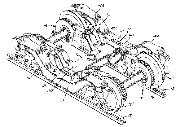
FIGURE 1 is a perspective view of a railway truck
assembly, without the bolcter assembly showing the location
of the side bearing height adjusters of the present
invention;
FIGURE 2 is a top view of Figure 1 with the
cab support coil spring removed from the bolster assernbly to
illustrate the position of the side bearing height adjusters
of the present invention relative to the bolster and the
truck frame;
FIGURE 3 is a side view Figure l;
FIGURE 4 is a side view of the side bearing height
adjusters;
E'IGURE 5 is a top view of Figure 4, and
FIGURE 6 is an end view of Figure 4.
Referring now to the drawings, and more particu~
larly to Figures 1 to 4, there is shown generally at 10, a
truck assembly for supporting a railway vehicle cab 11 on
rails 12. The truck assembly comprises essentially a truck
frame 13, as shown in Figure 1, which is defined by opposed
side frame sections 14 and 14a and a transverse section or
transom 15. The transom 15 usually extends substantially at
mid-length between the opposed side frame sections 14 and
14a. A pair of wheel assemblies 16 are supported between
opposed ends of the side frame sections 14 and 14a, as is
well known in the art.

~373~7
The improvement in the truck assembly of the
present invention resides in the provision of side bearing
height adjusters 17 removably secured on a flat top surface
18 of the truck frame, herein at the intersection of the
side members 14 and 14a and the transom 15. These side
bearing height adjusters 17 are spaced-apart on a respective
side of the truck frame and from a central pivot member 19
disposed centrally on the transom 15. The side bearing
height adjusters are provided with a bearing element 20
which is removably secured to retention elements 21 fixed to
the truck frame. The bearing element also has a top bearing
plate 22 with a friction support surface to provide a
restraining friction force against rotation of the bolster
assembly 23, disposed over the transom and extending to the
side frame sections 14 and 14a. The bolster assembly 23 is
provided with coil springs 24 to support a cab 11 thereon in
a manner well known in the art. Since the present invention
relates to the side bearing height adjusters, it is not
necessary to provide herein a detailed description of the
truck frame, wheel assemblies or bolster assembly but only
the main elements thereof. As also shown in Figures 1 and
2, the bolster assembly 23 is also provided with a pivot
post 25 secured centrally thereto whereby to be received in
the central pivot member 20 on the transom and in close
friction fit therein. A central pivot member 19 is herein
provided as a cup shape member and bearing means 26 is
provided between the cup and the post to permit horizontal
displacement between the bolster assembly and the truck
frame.

~373~7
Referring now to Figures 4, 5 and 6, there will be
described the construction of the bearing elemen-t 17. As
herein shown the bearing elemen-t is comprlsed oE a body
member 27 which is a substantially rectangular member having
a predetermined thickness and constitutes the height
adjustment element of the height adjuster assembly. A
locating cavity 28 is provided in a bottom wall of the body
member 27 whereby to receive therein an elastomeric pad 30,
herein constituted by a urethane material. A top section of
this pad is located in the cavity to maintain the pad in
alignment with the body member 27. At least, herein three
through bores 31 extend through the body member 27 in the
cavity to provide a vacuum break to locate the pad in the
cavity and also to facilitate the removal and replacement of
the pad or replacement of the height adjusting body member
27. A top bearing plate 32 which is also a rectangular
plate, is removably secured on a top wall 33 of the body
member 27 by means of removable fasteners 34. The bearing
plate 32 has a top friction support surface 35 constituted
by a lubricant bonded thereto. This friction surface is in
contact with a flat bottom wall (not shown) of the bolster
assembly 23.
As shown in Figure 1, a pair of spaced-apart
retention means herein a pair of rigid lugs 40 are removably
secured in transverse alignment and centrally on the
transom. These lugs are disposed in alignment, preferably,
but not exclusively over the side frame section 14 and 14a
as better seen in Figure 2. The coil springs 24 are
disposed over these side frame sections and the side bearing
height adjusters 17 between the spring retention flanges 41
so that the vertical load from the bolster is transferred

~7~7
to the truck frame through the side beariny hei,ght
adjusters. These side bearing height adjusters greatly
reduces from hunting, i.e., oscillations of the bolster and
cab relative to the frame, by restraining the horizontal
disp],acement of the truck frame relative to the bolster.
Referring again to Figures 4 to 6, it can be seen
that the body member 27 is provided with locating means in
the form of a pair of slots 42 which are of rectangular
shape and each located at an opposed end of the body member.
These slots are dimensioned to receive the lugs 40 in close
fit therein when the bearing element is positioned between
the pair of lugs. It is also pointed out that the
elastomeric pad has a predetermined thickness with a known
compression ratio and transfer the load and shear between
the body member and the truck frame. In use, the bearing
surfaces 16" of the wheels 16' usually wear due to hunting
or other type of vibrations. This causes the floor level of
the cab supported on the truck assembly to move downwards.
This causes all types of problems in that the floor of the
cabs are no longer aligned wi-th unloading or loading
platforms or other type platforms necessary to load and
unload commodities into freight cars, or people from
passenger cabs. However, with the present invention, when
the wheels wear down all that is necesary to elevate the
floor of the cab to the desired height is to jack or
ortherwise lift the bolster assembly from the truck frame in
the area indicated at 45 in Figure 2 and to lift off the
bearing element 20 from its position between the lugs 40.
This can be done easily by one person and the bearing
element is removed by hand.

2¢33r;~3
In order to provide height adjustment the
elastomeric member 30 and the friction plate 32 are removed
from the body 27 and a new body of greater thicknes.s
replaces the original body member so that the height
adjuster becomes thicker. The new bearing element 20 is
then placed back in position between the lugs 40. The same
procedure is repeated on the other side of the car body.
Accordingly, there is provided a simple, quick, inexpensive
and efficient manner in adjusting the distance between the
bolster assembly and the truck frame and to maintain the
bolster level on the truck frame, from side-to-side. The
side bearing height adjusters 17 further provide the
advantages of transferring the vertical load from the
bolster assembly to the truck frame and substantially
prevent the truck from hunting by restraining the rotation
of the truck frame relative to the bolster assembly.
It is within the ambit of the present invention to
cover any obvious modifications of the examples of the
preferred embodiment described herein, provided such
modifications fall within the scope of the appended claims.

Dessin représentatif
Une figure unique qui représente un dessin illustrant l'invention.
États administratifs

2024-08-01 : Dans le cadre de la transition vers les Brevets de nouvelle génération (BNG), la base de données sur les brevets canadiens (BDBC) contient désormais un Historique d'événement plus détaillé, qui reproduit le Journal des événements de notre nouvelle solution interne.

Veuillez noter que les événements débutant par « Inactive : » se réfèrent à des événements qui ne sont plus utilisés dans notre nouvelle solution interne.

Pour une meilleure compréhension de l'état de la demande ou brevet qui figure sur cette page, la rubrique Mise en garde , et les descriptions de Brevet , Historique d'événement , Taxes périodiques et Historique des paiements devraient être consultées.

Historique d'événement

Description Date
Inactive : CIB de MCD 2006-03-11
Demande non rétablie avant l'échéance 2001-03-07
Inactive : Morte - Aucune rép. dem. par.30(2) Règles 2001-03-07
Réputée abandonnée - omission de répondre à un avis sur les taxes pour le maintien en état 2001-02-28
Inactive : Abandon. - Aucune rép dem par.30(2) Règles 2000-03-07
Inactive : Dem. de l'examinateur par.30(2) Règles 1999-09-07
Lettre envoyée 1997-10-29
Inactive : Renseign. sur l'état - Complets dès date d'ent. journ. 1997-10-29
Inactive : Dem. traitée sur TS dès date d'ent. journal 1997-10-29
Exigences pour une requête d'examen - jugée conforme 1997-10-02
Toutes les exigences pour l'examen - jugée conforme 1997-10-02
Demande publiée (accessible au public) 1991-10-28

Historique d'abandonnement

Date d'abandonnement Raison Date de rétablissement
2001-02-28

Taxes périodiques

Le dernier paiement a été reçu le 2000-02-23

Avis : Si le paiement en totalité n'a pas été reçu au plus tard à la date indiquée, une taxe supplémentaire peut être imposée, soit une des taxes suivantes :

  • taxe de rétablissement ;
  • taxe pour paiement en souffrance ; ou
  • taxe additionnelle pour le renversement d'une péremption réputée.

Les taxes sur les brevets sont ajustées au 1er janvier de chaque année. Les montants ci-dessus sont les montants actuels s'ils sont reçus au plus tard le 31 décembre de l'année en cours.
Veuillez vous référer à la page web des taxes sur les brevets de l'OPIC pour voir tous les montants actuels des taxes.

Historique des taxes

Type de taxes Anniversaire Échéance Date payée
Requête d'examen - générale 1997-10-02
TM (demande, 7e anniv.) - générale 07 1998-03-02 1998-02-23
TM (demande, 8e anniv.) - générale 08 1999-03-01 1999-02-08
TM (demande, 9e anniv.) - générale 09 2000-02-28 2000-02-23
Titulaires au dossier

Les titulaires actuels et antérieures au dossier sont affichés en ordre alphabétique.

Titulaires actuels au dossier
BOMBARDIER INC.
Titulaires antérieures au dossier
RAYMOND DUMOULIN
Les propriétaires antérieurs qui ne figurent pas dans la liste des « Propriétaires au dossier » apparaîtront dans d'autres documents au dossier.
Documents

Pour visionner les fichiers sélectionnés, entrer le code reCAPTCHA :


Pour visualiser une image, cliquer sur un lien dans la colonne description du document. Pour télécharger l'image (les images), cliquer l'une ou plusieurs cases à cocher dans la première colonne et ensuite cliquer sur le bouton "Télécharger sélection en format PDF (archive Zip)" ou le bouton "Télécharger sélection (en un fichier PDF fusionné)".

Liste des documents de brevet publiés et non publiés sur la BDBC .

Si vous avez des difficultés à accéder au contenu, veuillez communiquer avec le Centre de services à la clientèle au 1-866-997-1936, ou envoyer un courriel au Centre de service à la clientèle de l'OPIC.


Description du
Document 
Date
(aaaa-mm-jj) 
Nombre de pages   Taille de l'image (Ko) 
Revendications 1994-02-26 4 103
Description 1994-02-26 7 230
Abrégé 1994-02-26 1 24
Dessins 1994-02-26 3 105
Dessin représentatif 1999-07-21 1 57
Accusé de réception de la requête d'examen 1997-10-28 1 178
Courtoisie - Lettre d'abandon (R30(2)) 2000-04-17 1 171
Courtoisie - Lettre d'abandon (taxe de maintien en état) 2001-03-27 1 182
Taxes 1997-02-03 1 64
Taxes 1996-02-14 1 64
Taxes 1995-02-20 1 66
Taxes 1994-02-03 1 71
Taxes 1993-02-17 1 38