Sélection de la langue

Search

Sommaire du brevet 2037404 

Énoncé de désistement de responsabilité concernant l'information provenant de tiers

Une partie des informations de ce site Web a été fournie par des sources externes. Le gouvernement du Canada n'assume aucune responsabilité concernant la précision, l'actualité ou la fiabilité des informations fournies par les sources externes. Les utilisateurs qui désirent employer cette information devraient consulter directement la source des informations. Le contenu fourni par les sources externes n'est pas assujetti aux exigences sur les langues officielles, la protection des renseignements personnels et l'accessibilité.

Disponibilité de l'Abrégé et des Revendications

L'apparition de différences dans le texte et l'image des Revendications et de l'Abrégé dépend du moment auquel le document est publié. Les textes des Revendications et de l'Abrégé sont affichés :

  • lorsque la demande peut être examinée par le public;
  • lorsque le brevet est émis (délivrance).
(12) Brevet: (11) CA 2037404
(54) Titre français: CATHETER A FIBRE OPTIQUE POUR L'ANGIOPLASTIE
(54) Titre anglais: ANGIOPLASTY LIGHT GUIDE CATHETER
Statut: Périmé et au-delà du délai pour l’annulation
Données bibliographiques
(51) Classification internationale des brevets (CIB):
  • A61B 18/24 (2006.01)
  • A61B 17/22 (2006.01)
  • A61M 25/10 (2013.01)
(72) Inventeurs :
  • HOFMANN, EUGEN (Suisse)
(73) Titulaires :
  • SCHNEIDER (EUROPE) AG
(71) Demandeurs :
  • SCHNEIDER (EUROPE) AG (Suisse)
(74) Agent: SMART & BIGGAR LP
(74) Co-agent:
(45) Délivré: 1998-03-31
(22) Date de dépôt: 1991-03-01
(41) Mise à la disponibilité du public: 1991-09-06
Requête d'examen: 1991-03-01
Licence disponible: S.O.
Cédé au domaine public: S.O.
(25) Langue des documents déposés: Anglais

Traité de coopération en matière de brevets (PCT): Non

(30) Données de priorité de la demande:
Numéro de la demande Pays / territoire Date
690/90-3 (Suisse) 1990-03-05

Abrégés

Abrégé français

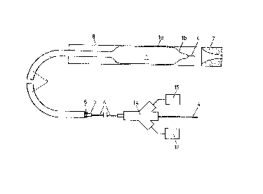
Cathéter à ballonnet pour angioplastie dans lequel le ballonnet comporte sur ses parois une série de guides de lumière laser, qui sont incrustés dans les parois du ballonnet. Ainsi, les extrémités distales de ces derniers peuvent être déplacées radialement vers l'extérieur et vers l'intérieur en modifiant la pression à l'intérieur du ballonnet.


Abrégé anglais


An angioplasty balloon catheter wherein the
balloon thereof has connectad to its wall a plurality
of laser light guides which are inlaid in the balloon
wall so that the distal ends of the liyht guides can be
moved radially outwardly and inwardly by changing
pressure within the balloon.

Revendications

Note : Les revendications sont présentées dans la langue officielle dans laquelle elles ont été soumises.


THE EMBODIMENTS OF THE INVENTION IN WHICH AN EXCLUSIVE
PROPERTY OR PRIVILEGE IS CLAIMED ARE DEFINED AS FOLLOWS:
1. Angioplasty light guide catheter for the removal of stenoses using
laser light energy, with a dilatation balloon to be introduced percutaneously into
the vessel to be treated and with several light guides which end in the area of the
dilatation balloon for emission and at the proximal end of a shaft of the catheter
for admission of the laser light, characterized in that the light guides have, at least
in the area of the dilatation balloon, a diameter which is not greater than the
thickness of the wall of the dilatation balloon and are inlaid in the wall in such a
way that, at their distal ends, they can be moved radially outwards and inwards by
means of pressure changes in the dilatation balloon while remaining substantially
parallel with the longitudinal axis of the catheter.
2. Catheter according to claim 1, characterized in that the light guides
are flexible phases with a diameter smaller than about 0.5 mm.
3. Catheter according to claim 1 or claim 2, characterized in that the
light guides are embedded in the wall of the dilatation balloon.
4. Catheter according to any one of claims 1 to 3, characterized in that
the wall has an inner layer on which an outer layer is applied, and in that the light
guides are embedded in the outer layer.
5. Catheter according to claim 4, characterized in that the outer layer is
-6-

made of silicone rubber.
6. Catheter according to any one of claims 1 to 5, characterized in thatthe wall of the dilatation balloon is made of relatively soft and flexible plastic
material.
7. Catheter according to any one of claims 1 to 6, characterized in thatit is connected to a pulsating xenon-chloride excimer laser.
- 7 -

Description

Note : Les descriptions sont présentées dans la langue officielle dans laquelle elles ont été soumises.


2037404
- 1 - 64680-602
ANGIOPLASTY LIGHT GUIDE CATHETER FOR THE REMOVAL
OF STENOSES USING LASER LIGHT ENERGY
The invention relates to an angioplasty light guide
catheter for the removal of stenoses using laser light energy.
The use of laser beams for the treatment of stenoses was
proposed more than 25 years ago. Although this method too, in
addition to the known balloon dilatation, permits treatment with-
out surgical intervention and from the start was very promising,
the opening of stenosed vessels using laser light has nevertheless
scarcely progressed beyond the experimental stage. An important
reason for this is that no suitable catheter was available which
permitted an acurate positioning of the light guides in the
vessel. Nor has a solution hitherto been found to the risk of
dissection of the vessel wall.
An angioplasty light guide catheter is known in which
the laser light is bundled with lenses. An angioplasty light
guide catheter is also known from an article in the periodical
Herz+Gefass 5 (1985) page 185, Figure 5, in which three concen-
trically arranged laser light guides can be held in the vessel
stable against the wall by means of a balloon. In this catheter
too, an acurate positioning and control of the laser light is not
possible, and the risk of dissection is relatively high. In this
case there is also the disadvantage that, with a catheter with a
wall-stable laser light guide, severe occlusions cannot be treated
successfully. In the case of such severe occlusions, a catheter
with a centrally arranged light guide, as is known from the
periodical JACC Volume 8 (5), November 1986; 1989-95 (Fig. 1),
would be better suited.

6~U3~4
The object of the invention is to provide a catheter of the said
generic type, with which the laser light can be controlled safely and simply, and
which is suitable for the treatment of stenoses of varying degrees, without any risk
of dissection of the vessel wall.
The invention provides angioplasty light guide catheter for the
removal of stenoses using laser light energy, with a dilatation balloon to be
introduced percutaneously into the vessel to be treated and with several light
guides which end in the area of the dilatation balloon for emission and at the
proximal end of a shaft of the catheter for admission of the laser light,
10 characterized in that the light guides have, at least in the area of the dilatation
balloon, a diameter which is not greater than the thickness of the wall of the
dilatation balloon and are inlaid in the wall in such a way that, at their distal ends,
they can be moved radially outwards and inwards by means of pressure changes
in the dilatation balloon while remaining substantially parallel with the longitudinal
axis of the catheter.
In the catheter according to the invention, the distance of the exit
points of the light guides from the centre line of the balloon is a function of the
pressure of the balloon fluid. This pressure can be altered and controlled
accurately and in a simple manner by the surgeon. In the case of a low pressure
20 and a correspondingly small diameter of the dilatation balloon, the laser light is
concentrated in the vessel centre and is therefore particularly suitable for the
treatment of severe stenoses. In the case of a higher pressure, the exit points lie
correspondingly closer to the inside wall of the vessel, and the outer-lying areas
64680-602

2037404
- 2a- 64680-602
of stenoses can also be removed correspondingly. Further
advantageous features will emerge from the dependent claims and
from the description.
An exemplary embodiment of the invention is illustrated
in greater detail below with reference to the drawings, in which:
Fig. 1 shows diagrammatically a stenosed vessel section
with the dilatation balloon inserted,
Fig. 2 shows a cross-section through a dilatation
balloon,
Fig. 3 shows a longitudinal section through the distal
end of a dilated balloon in a diagrammatically represented
stenosed vessel section,
Fig. 4 shows a longitudinal section through the

2037409
rear area of a dilatation balloon, and
Fig. 5 shows a cross-section through the shaft of
a catheter according to the invention.
Fig. 1 shows, purely diagrammatically, a blood
vessel 8 with a stenosis 7, and a catheter with a
dilatation balloon 1 and a catheter shaft 2 inserted
percutaneously into the vessel. The catheter is
inserted into the vessel 8 using a guide wire 4. The
guide wire 4 extends through the shaft 2 and the
dilatation balloon 1 and can emerge at a distal opening
18. As Fig. 5 shows, the shaft 2 is divided by a wall
10 into a lumen 11 for the guide wire 4 and a lumen 12
for pressure fluid. The lumen 12 is connected,
according to Fig. 4, via an opening 9 to the balloon
interior 13, and connected at the proximal end to a
suction and pressure pump 16. By means of the pump 16,
the pressure in the interior 13 of the dilatation
balloon 1 can be regulated accurately and,
consequently, the diameter of the balloon can be
regulated. When the catheter is introduced, the
dilatation balloon 1 is folded in a known manner. In
the unfolded state, the dilatation balloon 1, as can be
seen from Fig. 1, is externally cylindrical between the
two tapering ends.
According to Fig. 2, the wall 5 of the dilatation
balloon 1 consists of an inner layer 5a and an outer
layer 5b. The inner layer 5a consists of a relatively
soft plastic and the outer layer 5b preferably of
silicone rubber. In contrast to the known dilatation
balloons, the wall 5 of the dilatation balloon 1 is
elastically extensible within certain limits. Light
guide fibres or bundles 6 are stuck onto the inner
layer 5a and are covered by the outer layer 5b. These
light guides 6 are distributed uniformly over the

2037404
periphery of the wall 5 and run parallel to the
longitudinal direction of the catheter 6. When the
balloon 1 is dilated, the exit points 6a of the light
guides 6 lie in a circle and in a plane which
intersects the dilatation balloon approximately at the
transition between its cylindrical area la and its
distal tapered area lb. The light guides 6 also extend
over the entire length of the shaft 2 and are coupled
via a connection piece 14 to a laser device 15. The
device 15 is preferably a pulsating xenon-chloride
excimer laser. The light generated by the laser device
15 passes via the connection piece 14 and the shaft 2
to the exit points 6a of the light guides 6.
The light guides 6 have a diameter of for example
0.1 mm and are very flexible. The dilatation balloon
1 can thus be folded even with the light guides 6
inserted. The radial distance of the light guides 6
from the centre line of the dilatation balloon 1
- increases as the pressure of the fluid present in the
balloon increases. Accordingly, the distance of the
exit points 6a from the centre line of the dilatation
balloon 1 is a function of the pressure which can be
regulated by the pump 16. Since the wall 5 is
elastically extensible, it is possible, by means of the
pressure regulation, to arrange the exit points 6a in
circles of differing radii. Accordingly, the laser
beans emerging at the exit points 6a strike the
stenosis 7 at a greater or lesser distance from the
inner side of the vessel. When the pressure in the
dilatation balloon is relatively low, a correspondingly
intense laser light bundle is thus directed towards the
centre of the stenosis. In contrast, in the case of a
higher pressure, the more outer areas of the stenosis
7 are removed with less dense laser light.

203~lO4
As shown in Fig. 3, the dilatation balloon 1 is
positioned in front of the stenosis 7 for the removal
of the stenosis 7 using laser light. The position of
the dilatation catheter 1 can be observed using a
marker strip 17. In addition to the removal of the
stenosis using laser light energy, the use of
conventional balloon dilatation is also conceivable
with the catheter according to the invention. Thus,
without changing the catheter, a stenosis 7 can be
expanded with the dilatation balloon 1 before or after
treatment using laser light energy.

Dessin représentatif
Une figure unique qui représente un dessin illustrant l'invention.
États administratifs

2024-08-01 : Dans le cadre de la transition vers les Brevets de nouvelle génération (BNG), la base de données sur les brevets canadiens (BDBC) contient désormais un Historique d'événement plus détaillé, qui reproduit le Journal des événements de notre nouvelle solution interne.

Veuillez noter que les événements débutant par « Inactive : » se réfèrent à des événements qui ne sont plus utilisés dans notre nouvelle solution interne.

Pour une meilleure compréhension de l'état de la demande ou brevet qui figure sur cette page, la rubrique Mise en garde , et les descriptions de Brevet , Historique d'événement , Taxes périodiques et Historique des paiements devraient être consultées.

Historique d'événement

Description Date
Inactive : CIB enlevée 2021-10-18
Inactive : CIB attribuée 2021-10-18
Inactive : CIB expirée 2013-01-01
Inactive : CIB désactivée 2011-07-26
Inactive : CIB de MCD 2006-03-11
Inactive : CIB dérivée en 1re pos. est < 2006-03-11
Inactive : CIB de MCD 2006-03-11
Le délai pour l'annulation est expiré 2003-03-03
Lettre envoyée 2002-03-01
Inactive : TME en retard traitée 2000-03-27
Lettre envoyée 2000-03-01
Accordé par délivrance 1998-03-31
Inactive : Taxe finale reçue 1997-11-28
Préoctroi 1997-11-28
Lettre envoyée 1997-10-27
Un avis d'acceptation est envoyé 1997-10-27
Inactive : Dem. traitée sur TS dès date d'ent. journal 1997-10-23
Inactive : Renseign. sur l'état - Complets dès date d'ent. journ. 1997-10-23
Inactive : CIB en 1re position 1997-10-03
Inactive : CIB enlevée 1997-10-03
Inactive : CIB attribuée 1997-10-03
Inactive : CIB enlevée 1997-10-03
Inactive : CIB attribuée 1997-10-03
Inactive : Approuvée aux fins d'acceptation (AFA) 1997-09-11
Demande publiée (accessible au public) 1991-09-06
Toutes les exigences pour l'examen - jugée conforme 1991-03-01
Exigences pour une requête d'examen - jugée conforme 1991-03-01

Historique d'abandonnement

Il n'y a pas d'historique d'abandonnement

Taxes périodiques

Le dernier paiement a été reçu le 1997-11-05

Avis : Si le paiement en totalité n'a pas été reçu au plus tard à la date indiquée, une taxe supplémentaire peut être imposée, soit une des taxes suivantes :

  • taxe de rétablissement ;
  • taxe pour paiement en souffrance ; ou
  • taxe additionnelle pour le renversement d'une péremption réputée.

Les taxes sur les brevets sont ajustées au 1er janvier de chaque année. Les montants ci-dessus sont les montants actuels s'ils sont reçus au plus tard le 31 décembre de l'année en cours.
Veuillez vous référer à la page web des taxes sur les brevets de l'OPIC pour voir tous les montants actuels des taxes.

Historique des taxes

Type de taxes Anniversaire Échéance Date payée
TM (demande, 7e anniv.) - générale 07 1998-03-02 1997-11-05
Taxe finale - générale 1997-11-28
TM (brevet, 8e anniv.) - générale 1999-03-01 1999-02-23
Annulation de la péremption réputée 2000-03-01 2000-03-27
TM (brevet, 9e anniv.) - générale 2000-03-01 2000-03-27
TM (brevet, 10e anniv.) - générale 2001-03-01 2001-02-19
Titulaires au dossier

Les titulaires actuels et antérieures au dossier sont affichés en ordre alphabétique.

Titulaires actuels au dossier
SCHNEIDER (EUROPE) AG
Titulaires antérieures au dossier
EUGEN HOFMANN
Les propriétaires antérieurs qui ne figurent pas dans la liste des « Propriétaires au dossier » apparaîtront dans d'autres documents au dossier.
Documents

Pour visionner les fichiers sélectionnés, entrer le code reCAPTCHA :


Pour visualiser une image, cliquer sur un lien dans la colonne description du document (Temporairement non-disponible). Pour télécharger l'image (les images), cliquer l'une ou plusieurs cases à cocher dans la première colonne et ensuite cliquer sur le bouton "Télécharger sélection en format PDF (archive Zip)" ou le bouton "Télécharger sélection (en un fichier PDF fusionné)".

Liste des documents de brevet publiés et non publiés sur la BDBC .

Si vous avez des difficultés à accéder au contenu, veuillez communiquer avec le Centre de services à la clientèle au 1-866-997-1936, ou envoyer un courriel au Centre de service à la clientèle de l'OPIC.

({010=Tous les documents, 020=Au moment du dépôt, 030=Au moment de la mise à la disponibilité du public, 040=À la délivrance, 050=Examen, 060=Correspondance reçue, 070=Divers, 080=Correspondance envoyée, 090=Paiement})


Description du
Document 
Date
(aaaa-mm-jj) 
Nombre de pages   Taille de l'image (Ko) 
Description 1997-08-19 6 199
Revendications 1997-08-19 2 45
Abrégé 1994-03-04 1 12
Revendications 1994-03-04 2 52
Dessins 1994-03-04 2 63
Description 1994-03-04 6 199
Dessin représentatif 1998-03-08 1 5
Avis du commissaire - Demande jugée acceptable 1997-10-26 1 165
Avis concernant la taxe de maintien 2000-03-28 1 178
Quittance d'un paiement en retard 2000-04-05 1 171
Avis concernant la taxe de maintien 2002-04-01 1 179
Correspondance 1997-11-27 1 28
Taxes 2000-03-26 2 63
Taxes 1996-11-27 1 83
Taxes 1993-12-09 1 64
Taxes 1994-12-20 1 89
Taxes 1995-11-02 1 90
Taxes 1992-10-20 2 112
Correspondance de la poursuite 1994-07-12 3 108
Courtoisie - Lettre du bureau 1991-08-15 1 22
Demande de l'examinateur 1996-12-05 2 64
Demande de l'examinateur 1994-01-12 1 57
Correspondance de la poursuite 1997-08-07 1 28
Demande de l'examinateur 1997-07-17 2 36
Correspondance de la poursuite 1997-06-01 2 38