Note : Les descriptions sont présentées dans la langue officielle dans laquelle elles ont été soumises.
- 1 - 2 0 3 7 8 1 7
This invention relates to a flow sensor,
particularly a fluid flow meter, comprising a
cylindrical housing wherein, at least locally, near a
rotor mounted in said housing, a helicoidally moving
fluid flow is created by at least one jet propulsion
activating element.
Flow meters for gaseous or liquid fluids in
which the fluid is made to whirl in a housing in
order to act upon one rotor mounted in this housing,
are known.
Such or technically equivalent structures
are described in the following patents or patent
applications. European Patent Publications No. EP-O
228 577-Al published on July 15, 1987 and No. EP-0
031 629-Al published on July 8, 1981, both
Publications having Paulus Jacobus Peters as
inventor.
The functioning of the flow meters
according to these patents is based onto a simple
principle. In a cylindrical housing a wormlike
insert is mounted which imparts a spiral motion to
the fluid circulating axially through the housing.
By counting the rotations of the rotor, a
read out can be obtained which corresponds to the
passed fluid amount.
One will observe that the flow meters
described in these patent applications all comprise
an insert having at least one peripheral spiral
channel. The object of the insert is clearly to make
the passing fluid to whirl.
Such flow meters provided with inserts,
present serious drawbacks. It has appeared for
example extremely difficult to manufacture the insert
which has to fit closely in the housing, with a great
accuracy and without mutual deviation (deviation >
1%) .
`. ~
~ . ,
- l~ 2037817
The insert has been made from synthetic
material by means of a so-called screw mould. The
edges of the helicoidal channels of the insert are
"sharp". In practice this implies that "demoulding"
from the mould will cause little frayed ends and
other irregularities.
5~
~..
~ - 2 - 2037817
Due to the sharp edges, the material thickness of the
spiral channels walls is not everywhere the same. For
synthetic material, this implies that the curing of
these materials reaches very critical limits when
manufacturing said insert.
It may be useful to specify that the insert
(usually four spiral channels) has in many cases
dimensions of 4.6 mm x 4 mm. The channel width is
then 1 mm at the most whereas the wall thickness
ranges then from 0.4 mm to 0.2 mm. A deviation of
0.05 mm implies that the opening filling insert,
which has already to be applied with pressure, is
subjected to an additional pressure which is not
visible by eye, and which will influence the accuracy
or exactitude of the measurement negatively. It has
been determined experimentally that in the liquid
meters according to the hereabove patents or patent
applications, from a deviation of 0.02 mm when
manufacturing the insert, a flow deviation is
obtained which can be expressed in percent.
Notwithstanding these drawbacks, which are related as
well to the manufacture of the insert as to its
assembling in the housing, this component remains the
heart of said liquid meters. Further there are still
different reasons which causes that this insert,
which can be called in some way the heart of both
flow meters, is a very problematic component because:
(a) the housing of the insert is provided with walls
of 1 mm. Each deviation < 0.01 mm during the
synthetic material pressing and the resulting
film formation causes a measurement deviation of
some percents;
(b) as already described, the insert has to be
assembled helicoidally in the housing. This is
done by means of a counter mould by which the
head of the insert is protected, by the end of
- 2a - 2037817
the counter mould, at the moment the insert is
positioned against the stop edge;
(c) after the assembly of the insert, the flow meter
has to be tested, notably for each meter the
deviation has to be determined. As already
explained herein before, the walls of the spiral
channels, better known as the insert, are also
used to clamp this piece in its housing. Due to
the very small dimensions of all components, each
deviation < than 0.01 mm implies a deformation of
the
;~
2037817
housing which has a bad influence on the expected result. Each deviation
> 0.01 mm results in a clamping of the insert in its housing of a
lower quality. This means that for a prestressing of 0.020 mm, a
deviation of 0.01 mm equals already 50 %.
5 (d) The "heart" of the flow meters can only be tested if the two other
elementary components (i.e. housing and rotor) are assembled together
However a product with mutual deviations will always be obtained.
No two flow meters of this kind are similar within a small percen-
tage. The impossibility to realize this is caused by the insert
itself. Attempts to automatize the production of such and similar
f low meters did not have any success. The reasons theref ore have
been explained herein above at different places. This results in
a failure of a bigger production since the final product will always
be a heterogenous product and in that the intermediate measurement
controls, during the production will definitely remain necessary
for each flow meter.
An object of the invention is now to design a flow
sensor, particularly a fluid flow meter of a new and original concept
which remedies completely the hereabove explained drawbacks and
several problems related thereto, whereby a good production capacity
can be obtained, an automatic assembling of the components can be
assured and a flow sensor of very high quality can be expected.
In order to enable this according to the invention,
said jet propulsion activating element is formed in relief on a part
of the inner wall of said housing and is manufactured together with
the latter in one step, which housing is delimited opstream with respect
to said rotor by a stop plate serving as bearing for one end of the
shaft of this rotor, whereas the other end of the latter bears m a
little bridge which extends transversally through said chamber.
In a preferably implemented embodiment of the
invention, at least one but preferaby several passages are provided
between said stop plate and the inner wall of said housing and the
inner wall of said housing comprises several, for example four,
continuous projections between which said stop plate is clamped.
In a possible embodiment, said stop plate is provided,
at the side directed away from said rotor, with a bulge for directing
- ` 2037817
the circulating fluid towards said passages.
A very remarkable characteristic of the
invention consists in that said stop plate is
provided at the side which is directed away from said
bulge, with a disk shaped relief or local thickening
of this disk, which disk shaped relief influences
together with said jet propulsion activating elements
the flow characteristics of the fluid depending on
the height of said relief.
The jet propulsion activating elements
which are very characteristic for the invention, can
present several shapes for transforming the
circulating fluid into an eddy current. These
different embodiments wi~l be described and treated
separately hereinafter.
Therefore, in accordance with the present
invention, there is provided a fluid flow meter for
measuring a flow rate of a fluid, comprising a
cylindrical housing, a rotor mounted in said housing,
and at least one jet propulsion activating element
provided for creating a helicoidally moving fluid
flow at least locally near said rotor, characterized
in that said jet propulsion activating element is
formed in relief on a part of the inner wall of said
housing and in that said sensor further comprises a
stop plate which partly closes said housing and
defines at least one passage for the fluid between
its outer circumference and the inner circumference
of said housing.
Also in accordance with the present
invention, there is provided an apparatus for
measuring a fluid flow rate, comprising:
(a) a cylindrical housing formed as a
single integral piece having a through opening
defining an inner wall, the inner wall having an
~.
- 4a -
`- 2037817
enlarged diameter wall portion to provide an axial
inlet and having a narrower diameter wall portion at
an outlet providing a shoulder therebetween;
(b) a rotor mounted in the narrower
diameter wall portion of the housing;
(c) a jet propulsion activating element
formed in relief on the shoulder of the housing for
creating a helicoidally moving fluid flow in the
housing near the rotor; and
(d) a stop plate having an outer
circumference, the stop plate mounted in the enlarged
diameter wall portion of the housing defining at
least one fluid passage therein, the fluid passage
being between the outer circumference of the stop
plate and the enlarged diameter wall portion of the
inner wall.
Other details and advantages of the
invention will become apparent from the following
description of a flow sensor, particularly a fluid
flow meter according to the invention. This
description is only given by way of example and does
not limit the invention. The reference numerals
relate to the annexed figures.
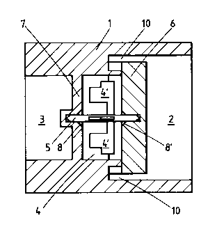
Figure 1 is a longitudinal section through
a flow sensor according to the invention.
Figure 2 is a view from above on the sensor
according to Figure 1 wherein the stop plate and the
rotor have been omitted.
Figures 3 to 6 illustrate four possible
embodiments of the jet propulsion activating elements
according to the invention.
Figures 7 to 13 show on another scale side
elevational views of different embodiments of the
part of the stop plate from a sensor according to the
invention which is situated upstream.
Figure 14 shows also a side elevational
view of a stop plate having at one side a relief, the
.~
i
- 2 0 3 7 8 1 7
height of which influences the flow characteristics
of the fluid.
This flow sensor shown in the different
figures consists of a housing 1 having wider and
narrower spaces 2 and 3 respectively. A rotor 4 is
mounted in the central axis of the housing 1,
substantially at the dividing plane between the wider
space 2 and the narrower space 3.
Upstream from the rotor 4, the shaft 5 of
the latter bears in a stop plate 6 whereas downstream
from the actual rotor
'..~
.
~ 5 ~ 2037817
the end of the shaft 5 bears in a little bridge 7
which extends in two directions through the space 2
of the housing 1. The little bridge 7 consists of a
cross-shaped component. Both ends of the shaft 5 of
the rotor 4 terminate into a point or in another
shape and in order to assure the automatic and
mechanical assembling of the rotor under good
conditions, the stop plate 6 as well as the little
bridge 7 show conically milled openings 8 and 8'.
The stop plate 6 is clamped between four
inwards extending projections 9 (figure 2). The
disc-shaped stop plate 6 can thus be pushed and
clamped very easily into its place in the housing 1,
at least in the wider space 2 of the latter between
the four continuous projections 9. Such an
arrangement makes the assembly of the components very
much easier.
Between the inner wall of the housing 1,
near the wider space 2 of the latter, and the outer
ZO edge of the stop plate 6, four passages 10 are thus
formed. The fluid circulating in the housing 1 from
the space 2 to the space 3 drives thus the blades 4'
of the rotor 4 according to a direction which is
substantially at right angles with respect to the
shaft 5 of this rotor. In order to obtain this,
several types of jet propulsion activating elements
are possible according to the invention.
Characterizing for the invention is the
fact that these jet propulsion activating elements
form one part with the housing 1 and the little
bridge 7. The big advantages resulting from this
concept are very clear. Indeed, in contrast with the
structures explained in the introductory part, in
which use is made of an insert, the essential part of
the flow sensor can now be manufactured in one step.
As already mentioned, the essential part of the flow
sensor comprises the housing 1, the little bridge 7
; ~
`-- 20~7817
-- 6
and said jet propulsion activating elements, the
different possible embodiments of which will be
described.
First the fact that upstream from the stop
plate 6 a pin 11 can be provided (figure 7) can yet
be pointed out. This pin is especially intended to
enable the automatic assembly of the stop plate 6.
In order to optimalize the aero- or
hydrodynamic structure of the fluid moving from the
space 2 to the space 3, a bulge which is part of the
stop plate 6, can be provided while maintaining said
pin 11 or instead of the latter. This bulge can
present different shapes. According to figure 8, this
bulge can take the shape of a triangle 12 whereas in
figure 9 this can be a smaller triangle 13, the base
of which coincides with a rectangle 14.
Another possible embodiment is shown in
figure 10 wherein a triangular bulge 15 having two
concave sides can be seen. Yet another, however from
an aero- or hydrodynamic point of view less
advantageous embodiment, consists in a rectangular 16
(figure 11). Finally, the same effect can also be
obtained by applying a vault shaped body 17
comprising planes set-up according to an arch (figure
12).
The bulge 17' according to figure 13 has an
aspherical shape.
The jet propulsion activating elements
which, as already emphasized, are together with the
little bridge 7 part of the housing 1 of the flow
sensor, can take several shapes, four of which are
shown in figures 3 to 6 by way of example.
A first embodiment is shown in figure 3
wherein the jet propulsion activating elements 18
present such a profile that between two adjoining
sides of such elements a curved channel is formed,
the side walls of which are substantially parallel.
_ 7 _ 2037817
The way the entering fluid is made to whirl by the
presence of said jet propulsion activating elements
18, is indicated by the little arrows.
In figure 4 the fluid is also made to whirl
by curved jet propulsion activating elements 19 which
partly present a straight wall 20 forming together
with the wall 21 of an adjoining jet propulsion
activating element 19 a channel with two parallel
walls. Also in this case the fluid is made to whirl
by the fact that the entering fluid is deflected
against the concave inner side 22 of a jet propulsion
activating element.
Figure 5 shows a particular embodiment
wherein triangular jet propulsion activating elements
23 are set up in such a manner that the entering
fluid which is guided between two parallel walls 24
and 25 of the respective elements, is still made to
whirl according to the same principle.
The variant according to figure 6 is
related to the embodiment according to figure 3
except in that between two jet propulsion activating
elements 26 a wedge shaped channel is formed. Indeed
the sides 27 and 28 of two adjoining elements define
a channel that becomes narrower into the direction of
the arrows. The entering fluid is however deflected
by the concave wall 29 and by the concave part of the
wall 29 of each jet propulsion activating element.
An analogous set-up of the jet propulsion
activating elements can be seen in Figure 2 wherein
two electronic elements 30 and 31 for measuring the
fluid flow rate by means of an infrared beam and/or a
voltmeter, are provided diametrially opposite to one
another. In this embodiment, related to the
embodiment according to Figure 3, the jet propulsion
activating elements 32 define channels 32', the
section of which reduces progressively in the
direction of the outlet.
! ~
"f~`
- 7a - 2037~1~
In the new structure of the flow sensor
according to the invention, the role which can be
fulfilled by the stop plate should still be pointed
out.
5By providing a rellef 33 (figure 14) on the
side of the stop plate 6 facing the rotor 4, the flow
characteristics of the fluid and its effect on the
rotor 4 can be influenced.
Depending on the needs of the flow sensor
lOusers, stop plates 6 can be supplied, having a relief
with different heights. Figure 14 shows a stop plate
6 of a certain height. It will be immediately clear
that the use of stop plates of different heights
defines the "channel size" of the channel formed by
15the jet propulsion activating elements. This offers
the important advantage that the flow sensor can be
adapted to the user's needs without having to modify
the basic mould in which the housing, bridge and jet
propulsion elements included, are formed in one spray
20step.
In this way, a so-called variable flow
control is now possible, i.e. the flow sensor
according to the invention can be adapted to the flow
rates to be measured. Indeed, the same housing,
25equipped with a stop plate 6 showing another relief
will, as already
~r
,~
2û37817
explained, give rise to completely different flow characteristics.
The use of stop plates having different reliefs allows to obtain a higher
accuracy and a better linearity by using a stop plate which is appropriate
for a certain flow rate range. This is important since the flow sensor
5 has to respond as linearly as possible in the range wherein it is used.
In practice, taking into account the known needs
of the market, at least seven different sensors will have to be used
when implementing the techniques known up to now.
With the structures according to the invention, the
10 same demand can be fulfilled for example by supplying three different
housings which can be used in combination with stop plates with adjusted
relief heights.
It will be immediately clear that from the point
of view of "production" as well as from the point of view of "use",
15 the flow sensor implies a very important improvement. Of course,
this remark applies as well to the jet propulsion activating elements
discussed in the preamble as to the structure of the stop plate and
this as well on the "production" level as on the "use" level.
It is clear that the invention is not limited to the
20 embodiments described hereabove and that many modif ications could
be applied to them. In the first place it is clear that the number
of jet propulsion activating elements per flow sensor is not limited
to the shown examples. At least one jet propulsion activating element
may give the same result. The relief 33 on the stop plates 6 can
25 show very various heights or characteristics.