Note : Les descriptions sont présentées dans la langue officielle dans laquelle elles ont été soumises.
2~3801~
-
LOCKING TRAILER COUPLING
Backqround and Summary of the Invention
This invention relates to a trailer coupling
that receives a drawbar having an annular eye and has a
locking mechanism that prevents accidental displacement
of the drawbar from the coupling.
Trailer couplings that receive a drawbar having
an annular eye on an upwardly-projecting pintle or a hook
utilize two types of latches to prevent the drawbar from
becoming accidentally dislodged from the pintle. In one
type of coupling the latch rotates about an axis that is
horizontally displaced from the pintle, thereby allowing
the latch to be rotated upwardly and permit the drawbar
to be inserted below it. On the other type of coupling
the latch rotates about an axis which is vertically dis-
placed from the pintle, thereby allowing the latch to be
rotated forwardly to completely uncover the pintle. The
advantage of this latter type of coupling is that the
latch can be opened merely by pushing the drawbar rear-
wardly against the face of the latch. The disadvantage
of the latter type of hitch is that it is difficult to
make it as strong as the former type. Examples of
couplings where the latch is lifted are Blacklaw, U.S.
Patent No. 4,721,324, Weiss, U.S. Patent No. 2,842,380,
Weiss, U.S. Patent No. 2,766,995, and FIGS. 1 and 2 of
Weiss, U.S. Patent No. 2,491,143. An example of a
coupling where the latch is rotated forwardly is FIG. 4
of Weiss '143.
All of the prior art drawbar-receiving
couplings have a locking mechanism that prevents acci-
dental opening of the latch. However, these locking
mechanisms are either complex, which makes them expen-
sive, or difficult to operate, which makes them
commercially undesirable, or both.
The subject invention overcomes the foregoing
shortcomings of the prior art couplings by providing a
~L
2038015
body that can be attached to a towing vehicle and has an
outwardly and upwardly-projecting pintle that is
configured to receive the eye of the drawbar. A latch
that is rotatably mounted in the body is normally
oriented in a latched position where it engages the
extremity of the pintle to prevent removal or installa-
tion of the drawbar. The latch is rotatable forwardly
toward the body to displace it from the pintle to allow
removal or installation of the drawbar.
A pawl that is rotatably mounted on the body
forwardly of the latch is normally oriented in a locked
position where it engages the latch and prevents rotation
of the latch from its latched position. When the drawbar
is to be inserted onto or removed from the pintle, the
latch can be rotated by first rotating the pawl to where
it does not engage the latch. In a preferred embodiment
of the invention, the latch includes a forwardly-
projecting tang that is engaged by the pawl. In addi-
tion, the pawl has a rearwardly-extending lip that fits
under the tang when the pawl is released after the latch
is rotated to its unlatched position, thereby holding the
latch open. Rotation of the pawl to its unlocked posi-
tion again, releases the latch and allows it to rotate
back to its latched position.
In operation, a drawbar can be connected to the
coupling merely by rotating the pawl to its unlocked
position, placing the drawbar against the face of the
latch, and urging it forwardly to where it can be placed
over the pintle. When the drawbar drops over the pintle
the latch returns to its normally latched position where
it prevents the drawbar from being removed from the
pintle. The pawl is then released to prevent rotation of
the latch from its latched position. When the drawbar is
to be removed from the coupling the pawl is rotated to
its unlocked position, the latch is rotated to its
unlatched position and the drawbar is lifted off of the
pintle.
203801~
_ 3
Accordingly, it is a principal object of the
present invention to provide a trailer coupling that
accepts a drawbar having an annular eye and has a locking
mechanism that is deactivated by rotating a single pawl.
It is a further object of the subject invention
to provide such a trailer coupling in which the locking
mechanism can be deactivated with one hand.
It is a still further object of the subject
invention to provide such a trailer coupling that is
inexpensive to construct and simple to operate.
The foregoing and other objectives, features
and advantages of the present invention will be more
readily understood upon consideration of the following
detailed description of the invention taken in conjunc-
tion with the accompanying drawings.
Brief Description of the Drawings
FIG. 1 is a side elevation view, partially
broken away to show hidden detail, of a trailer coupling
embodying the features of the subject invention.
FIG. 2 is a rear elevation view of the trailer
coupling.
FIGS. 3 and 4 are fragmentary side elevational
views, showing the operation of the coupling's locking
mechanism.
Preferred Embodiment of the Invention
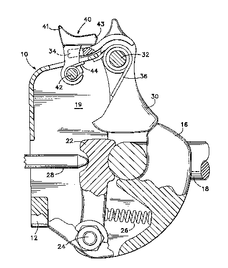
Referring to FIGS. 1 and 2 of the drawings, thetrailer coupling of the subject invention comprises a
body 10 having a flat base 12 with bolt holes 14 at its
corners to permit attachment of the coupling to a towing
vehicle (not shown). Extending rearwardly and upwardly
from the lower portion of the body 10 is a J-shaped
pintle 16. The upwardly-extending portion of the pintle
is cylindrical and is configured to receive the eye of a
drawbar 18 that is attached to the device being towed
(not shown). The upper portion of the body 16 includes
20380 iS
_ 4
spaced-apart side walls 19 that define a cavity 20
between them. Located at the bottom of the cavity is a
friction shoe 22 that is pivotally mounted on a bolt 24
so that it can be placed into contact with the drawbar 18
after the drawbar is placed in the pintle. A spring 26
normally urges the friction shoe away from the drawbar in
order to facilitate installation of the drawbar on the
pintle, and a ram 28, which is coupled to a pneumatic
cylinder (not shown), urges the friction shoe into
contact with the drawbar after it is installed on the
pintle.
Mounted rotatably in the body 10, between the
side walls 19, is a latch 30. A bolt 32 extending
through mating holes in the side walls and the upper rear
portion of the latch allows the latch to rotate between a
latched position, FIG. 1, where it engages the pintle and
overlies the drawbar to prevent removal of the drawbar
from the pintle, and an unlatched position, FIG. 3, where
it is displaced from the pintle toward the body. The
latch includes a tang 34 that extends forwardly from the
remainder of the latch, on the opposite side of the bolt
32, and is positioned at the top of the cavity 20 when
the latch is in its latched position. A spring 36
normally urges the latch to its latched position. The
rearwardly-facing surface of the latch is arcuate which
facilitates installation of the drawbar onto the
coupling, as will be more fully explained later.
Located forwardly of the latch is a pawl 40
that also fits between the side walls 19 and is rotatably
mounted on a bolt 42. The pawl 40 is rotatable between a
locked position, FIG. 1, where it overlies the tang 34 to
prevent raising of the tang, and thus rotation of the
latch, and an unlocked position, FIG. 4, where rotation
of the latch is possible.- The pawl includes a rear-
wardly-ext~n~;ng lip 43 that fits under the tang on the
latch when the pawl is returned to its locked position
after the latch has been rotated to its unlatched posi-
2~38015
_ 5
tion. A spring 44 normally urges the pawl to its lockedposition. A thumb grip 41 located at the upper extremity
of the pawl permits the pawl to be rotated to its
unlocked position simply by pushing forwardly against the
thumb grip.
In operation, all that is required for an
operator to couple the drawbar to the coupling is to
rotate the pawl 40 forwardly to its unlocked position,
FIG. 4. The latch then is free to be rotated to its
unlatched position, FIG. 3, and the curved rear face of
the latch permits this to be accomplished merely by
placing the drawbar 18 against the latch and pushing it
forwardly. Once the drawbar is installed on the pintle
16, the spring 36 urges the latch back to its latched
position, and the spring 44 urges the pawl 40 back to its
locked position, where it overlies the tang 34, FIG. 1.
Thus the drawbar is prevented from becoming dislodged
from the pintle by the latch and the pawl prevents the
latch from inadvertently opening.
To remove the drawbar from the coupling, the
operator must first rotate the pawl 40 to its unlocked
position and then rotate the latch to its unlatched posi-
tion. The drawbar can then be lifted up and off of the
pintle.
Whenever the latch is rotated to its latched
position it can be held there merely by releasing the
pawl and thereby causing the lip 43 to move under the
tang where it prevents rotation of the latch. The latch
can be released simply by again rotating the pawl to its
unlocked position.
The terms and expressions which have been
employed in the foregoing specification are used therein
as terms of description and not of limitation, and there
is no intention, in the use of such terms and expres-
sions, of excluding equivalents of the features shown anddescribed or portions thereof, it being recognized that
2038015
the scope of the invention is defined and limited only by
the claims which follow.