Sélection de la langue

Search

Sommaire du brevet 2038385 

Énoncé de désistement de responsabilité concernant l'information provenant de tiers

Une partie des informations de ce site Web a été fournie par des sources externes. Le gouvernement du Canada n'assume aucune responsabilité concernant la précision, l'actualité ou la fiabilité des informations fournies par les sources externes. Les utilisateurs qui désirent employer cette information devraient consulter directement la source des informations. Le contenu fourni par les sources externes n'est pas assujetti aux exigences sur les langues officielles, la protection des renseignements personnels et l'accessibilité.

Disponibilité de l'Abrégé et des Revendications

L'apparition de différences dans le texte et l'image des Revendications et de l'Abrégé dépend du moment auquel le document est publié. Les textes des Revendications et de l'Abrégé sont affichés :

  • lorsque la demande peut être examinée par le public;
  • lorsque le brevet est émis (délivrance).
(12) Brevet: (11) CA 2038385
(54) Titre français: CAPTEUR THERMOMETRIQUE POUR DETENDEUR THERMOSTATIQUE DU FLUIDE FRIGORIGENE
(54) Titre anglais: SENSING REFRIGERANT TEMPERATURE IN A THERMOSTATIC EXPANSION VALVE
Statut: Périmé et au-delà du délai pour l’annulation
Données bibliographiques
(51) Classification internationale des brevets (CIB):
  • G01K 7/22 (2006.01)
  • G05D 23/13 (2006.01)
  • G05D 23/24 (2006.01)
(72) Inventeurs :
  • GLENNON, THOMAS F. (Etats-Unis d'Amérique)
  • TORRENCE, ROBERT J. (Etats-Unis d'Amérique)
(73) Titulaires :
  • PARKER-HANNIFIN CORPORATION
(71) Demandeurs :
(74) Agent: BORDEN LADNER GERVAIS LLP
(74) Co-agent:
(45) Délivré: 1996-09-24
(22) Date de dépôt: 1991-03-18
(41) Mise à la disponibilité du public: 1991-09-20
Requête d'examen: 1993-10-21
Licence disponible: S.O.
Cédé au domaine public: S.O.
(25) Langue des documents déposés: Anglais

Traité de coopération en matière de brevets (PCT): Non

(30) Données de priorité de la demande:
Numéro de la demande Pays / territoire Date
495,182 (Etats-Unis d'Amérique) 1990-03-19

Abrégés

Abrégé anglais


A mechanical refrigerant thermal expansion valve has a
sensing port sealed with a cupped shape closure received
therein and sealed about the cup rim. A cover assembly is
removeably attached to the valve over the cup with a
thermistor extending into the cup which is filled with
thermally conductive grease for thermal conductivity
between the cup and the thermistor. The cover assembly
has an electrical connector provided thereon. The
thermistor is preferably mounted on printed circuit
board potted in the cover which may include electronic
signal logic and power switching circuitry.

Revendications

Note : Les revendications sont présentées dans la langue officielle dans laquelle elles ont été soumises.


-7-
THE EMBODIMENTS OF THE INVENTION IN WHICH AN EXCLUSIVE PROPERTY OR
PRIVILEGE IS CLAIMED ARE DEFINED AS FOLLOWS:
1. A valve assembly for controlling flow of refrigerant
to a heat exchanger comprising:
(a) body means defining an inlet adapted for receiving
pressurized refrigerant said body means including
means for restricting flow and an outlet for
discharging flow at a significantly reduced pressure,
said outlet adapted for connection to said heat
exchanger;
(b) means defining a continuous passage through said
body means, said passage adapted for connection to
receive therethrough frigerant flow discharging from a
heat exchanger;
(c) said body means defining a port communicating
exteriorly with said continuous passage;
(d) means defining a cup shaped closure for said port,
said closure sealingly attached thereover with the
open end of said cup shape exteriorly thereof;
(e) thermistor means received in said cup shaped
closure and including electrical attachment means
accessible esteriorly of said closure and adapted
for electrical attachment thereto; and,
(f) a thermally conductive fluidized medium disposed
in said cup shape about said thermistor for providing
heat-transfer between said cup-shaped closure and said
thermistor.
2. The assembly defined in claim 1 wherein said closure
has a generally cup shaped configuration with the open end
therof disposed to the exterior of said body means with
said thermistor received in said cup shape; and, said
thermally conductive medium has thermal resistance of
about 0.06° C per Watt.

-8-
3. The assembly defined in claim 1 wherein said closure
has a generally cup shaped configuration with the open end
thereof facing interiorly of said port; cover means
received over said cup with said thermistor extending
therefrom; and, said attachment means extends from said
thermistor means exteriorly through the wall of said
cover means.
4. The assembly defined in claim 1 wherein said closure
employs a resilient seal ring thereabout and is secured to
said body means by deformation of material.
5. The assembly defined in claim 1 wherein said closure
is secured to said body means by deforming the material of
said body means over the periphery of said closure means.
6. The assembly defined in claim 1 wherein said closure
is secured to said body means by ring staking.
7. A sensing assembly for sensing fluid temperature in a
pressurized flow system comprising:
(a) a closure means having a cavity formed therein and
adapted for attachment to a valve body;
(b) cover means having circuit board means potted
therein;
(c) thermistor means extending from said board means;
and,
(d) electrical connector means extending from said
board and through the wall of said cover means; and
(e) a fluidized thermally conductive medium in said
cavity for effecting heat transfer between said
closure and said thermistor means.

- 9 -
8. The assembly-defined in claim 7 further comprising
post means extending from said board means for supporting
said thermistor means.
9. The assembly defined in claim 7 wherein said closure
means includes shroud means extending therefrom for
protecting said electrical connector means.
10. A method of providing an electrical temperature
sensor in a pressurized fluid system comprising the steps
of:
(a) providing a cup shaped closure and disposing the
closed end of said cup shape in a port in said system
and sealing said port about the periphery of said cup
shape; and,
(b) positioning and retaining a thermistor in said cup
shape; and,
(c) surrounding said thermistor in said cup shape with
a fluidized thermally conductive medium and effecting
heat transfer between said closure and said thermistor.
11. The method defined in claim 10 wherein said step of
retaining said thermistor means includes the steps of
securing said thermistor to cover means and releasably
attaching said cover means over said cup shaped closure.
12. The method defined in claim 10, wherein said step of
retaining said thermistor means includes the steps of
securing said thermistor to a printed circuit means,
securing said printed circuit means to a cover means and
releasably attaching said cover means over said cup shaped
closure.

- 10 -
13. The method defined in claim 10, wherein said step of
retaining said thermistor means includes the step of
securing said printed circuit means to a cover means and
potting said printed circuit means and releasably attaching
said cover means over said cup shaped closure.
14. A valve assembly for controlling flow of refrigerant
to a heat exchanger comprising:
(a) body means defining an inlet passage adapted for
receiving pressurized refrigerant, said body means
including means for restricting flow and an outlet passage
for discharging flow at a significantly reduced pressure,
said outlet passage adapted for connection to said heat
exchanger;
(b) means defining a continuous passage through said
body means, said passage adapted for connection to receive
therethrough refrigerant flow discharging from a heat
exchanger;
(c) said body means defining a sensing port
communicating with one of said passages;
(d) means defining a cup-shaped closure for said
sensing port, said closure sealingly attached thereover
with the open end of said cup shape exteriorly thereof;
(e) thermistor means received in said cup shape and
including electrical attachment means accessible exteriorly
of said closure and adapted for electrical attachment
thereto; and
(f) a thermally conductive fluidized medium disposed
in said cup shape about said thermistor for providing heat
transfer between said cup shaped closure and said
thermistor.
15. The assembly defined in claim 14, wherein said
thermally conductive medium has a thermal resistance of
about 0.06°C per Watt.

Description

Note : Les descriptions sont présentées dans la langue officielle dans laquelle elles ont été soumises.

SENSING REFRIGERANT , r. ~KATURE IN A
~ ~IOSTATIC B PANSION VALVE
2038385
BACKGROUND OF THE lNv~ lON
The present invention relates to systems for
controlling the flow of refrigerant in a refrigeration or
air conditioning system of the type employing the well
known mechanical thermal expansion valve. Typically,
valves of this type have an auxiliary passage therethrough
adapted for attachment to the discharge line of the
refrigerant evaporator for receiving flow therefrom and
for connection to the compressor suction return line. The
auxiliary passage through the valve body provides a
convenient location to sense the temperature of the
evaporator discharge for purposes of providing an
electric control signal which may be employed in a
micro-computer for controlling the operation of the
- compressor clutch and condenser cooling fan.
Where it is desired to provide electrical sensing of
the temperature in the auxiliary refrigerant passage in
the thermostatic expansion valve, it has been found
desirable to employ a thermistor in the passage for direct
fluid temperature sensing. However, providing the
mountinq of the thermistor through the valve block from
the exterior thereof and to provide adequate sealing
around the thermistor for preventing leakage of the
gaseous refrigerant has been troublesome in high-volume
mass production. Heretofore, it has been the practice to

- 203838~i
_ -2-
mount the thermistor on a metal flange and secure the
flange to the periphery of a port formed in the valve body
to access the auxiliary refriqerant passage. This
technique for mounting the thermistor as a sub-assembly
has been found to be troublesome in high volume production
of the valves where breakage of the thermistor has been
experienced during the sealing operation which typically
employ metal staking. Accordingly, it has been desired to
provide a way or means of attaching a thermistor to a
sensing port in the valve block after the port has been
sealed to retain the pressurized gaseous refrigerant.
It has further been desired in providing a refrigerant
temperature sensor in a thermal expansion valve passage to
incorporate electronic circuitry at the thermistor
location in order that the circuitry may be heat sinked
to the low temperature valve block and thereby provide
cooling for solid state switching devices handling
substantial electrical current flow.
SUMMARY OF THE lNv~:NlION
The present invention provides a mechanical thermal
expansion valve for controlling refrigerant flow in a
refrigeration or air conditioning system. An auxiliary
passage is provided in the valve block for permitting
refrigerant discharging from the evaporator to flow
through the block to the compressor suction return port.
A thermistor is disposed through a sensing port in the
valve block to sense temperature of the refrigerant
flowing and the refrigerant return passage. In one
embodiment, a cup shape closure has the closed end thereof
received in the sensing port with the periphery thereof
sealed about the port. A thermistor is received in the cup
from the exterior therof and secured therein with

_3_ 203838-S
thermally conductive grease disposed to provide heat
transfer between the wall of the cup and the thermistor.
The thermistor is preferably mounted on a printed circuit
board received in a cup-shaped cover with the closed end
extending exteriorly of the body with the open end sealed
about the periphery of the sensing port. An electrical
connector extends from the printed circuit board through
the wall of the cover and exteriorly thereof for
electrical connection thereto. The printed circuit board
is potted in the cup and may contain power switching
devices which are cooled by the refrigerant contacting the
potting compound surrounding the printed circuit board.
BRIEF DESCRIPTION OF THE DRAWINGS
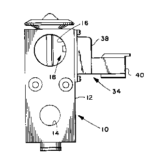
Figure 1 is a side elevation view of a thermal
expansion valve assembly employing the present invention;
Figure 2 is a right hand side view of the valve
assembly of Figure l;
Figure 3 is a partial section view taken along section
indicating lines 3-3 of Figure 2; and,
DETAILED DESCRIPTION
Referring to Figure 1, the valve assembly of the
present invention is indicated generally at 10 as having a
valve body 12 having a valved outlet port 14 and an
auxiliary through passage 16 spaced therefrom which
extends continuously through the valve block 12. The
passage 16 has a temperature sensor assembly indicated
generally at 18 extending through the valve block into the
passage 16.
The temperature sensor assembly 18 is received through
a port hole 20 formed in the valve block 12 for

~ ~4~ 2038385
communicating the exterior thereof with the passage 16.
The exterior end of port 20 is counter bored to enlarged
diameter 22; and, the intersection of the diameter 20 with
the bottom 24 of the counterbore is chamfered at 26 to
provide a seat for sealing ring 28.
A generally deep drawn cup-shaped closure 30 is
provided and has a radially outwardly extending flange 32
provided thereon. The closed end of closure 30 is
received in port 20 and the flange 32 is secured over
O-ring 28 and retained in the bottom 24 of the counterbore
by suitable retaining means, as for example, deformation
of material of the body over the flange 32. In the
presently preferred practice, the flange 30 is ring staked
in place over the O-ring. However, it will be understood
that other fastening expedients may be employed.
A housing or cover, indicated generally at 34, has a
peripheral flange 36 formed thereabout and has a generally
cup shaped central section 38 with an electrical
receptacle portion 40 extending outwardly from the closed
end of the cup shaped central portion 38. The flange 36
is retained on the surface of the valve block 12 with the
cup shaped central portion disposed over the counterbore
22; and, the flange 36 is retained on the valve block by
suitable fastening expedients as, for example, screws 42.
The cup shaped central portion 38 of cover 34 has a
shoulder or ledge 44 formed peripherally about the inner
side wall thereof and has received thereon a printed
circuit board 46 which has a tubular or hollow support
stanchion or post 48 extending therefrom. The printed
circuit board also has a plurality of electrical connector
pins 50, 52, 54 attached thereto and extending outwardly
from the opposite side of the circuit board 46 from post
48. The pins extend outwardly through aperatures, such as
aperture 56 shown in Figure 3 for pin 52, and into a

~_ ~5~ 203838~
protective the shroud 40 adapted for receiving and guiding
therein a mating electrical connector (not shown).
The printed circuit board 46 and its attachments are
potted into the central portion 38 of the cover by a
suitable potting compound indicated by reference numeral
58 in figure 3.
A sensing thermistor indicated by reference numeral 60
in FIG. 3 is received through the post 48 and is attached
to the circuitry of circuit board 46 with the end thereof
extending out of the post and into the interior of the cup
30.
The end of the thermistor 60 in cup 30 is surrounded
by suitable thermally conductive grease 62 or other
suitable fluidized thermally conductive medium which may
be suitably compacted and retained about the thermistor
for conducting heat between the thermistor and the wall of
the cup 30. In the presently preferred practice, the
grease has a thermal resistance of 0.06 C per Watt and
is obtainable from Wakefield Engineering, Inc., Wakefield,
Massachussets, 01880 under the manufacturer's designation
120-8.
The structural arrangement of the cover of the
assembly 34 of the present invention thus permits the port
20 in the valve block to be sealed by cup 20 as a
completed subassembly. The thermistor is then mounted on
the cover assembly 34 and assembled onto the valve block
of the exterior thereof in a removable manner without
interrupting the seal of the port 20 in the valve block.
This unique arrangement enables changing or replacement of
the thermistor 60 without requiring discharging of the
sealed refrigerant in the refrigeration system.
The present invention also permits a mechanical
thermal expansion valve to be conveniently outfitted with
electrical temperature sensing for providing signals to a

-6- 203838~
microprocessor for electrical control of the refrigeration
system component such as the compressor clutch and the
condenser fan.
The preferred means of mounting the thermistor on a
printed circuit board permits the compact mounting of
solid state switching devices, for example FET switches,
on the printed circuit board along with suitable switching
logic to eliminate the need of long leads for the low
power thermistor signal to the power switching circuitry.
Although the invention has herein above been described
with respect to the illustrated embodiments, it will be
understood that the invention is capable of modification
and variation and is limited only by the following claims.

Dessin représentatif
Une figure unique qui représente un dessin illustrant l'invention.
États administratifs

2024-08-01 : Dans le cadre de la transition vers les Brevets de nouvelle génération (BNG), la base de données sur les brevets canadiens (BDBC) contient désormais un Historique d'événement plus détaillé, qui reproduit le Journal des événements de notre nouvelle solution interne.

Veuillez noter que les événements débutant par « Inactive : » se réfèrent à des événements qui ne sont plus utilisés dans notre nouvelle solution interne.

Pour une meilleure compréhension de l'état de la demande ou brevet qui figure sur cette page, la rubrique Mise en garde , et les descriptions de Brevet , Historique d'événement , Taxes périodiques et Historique des paiements devraient être consultées.

Historique d'événement

Description Date
Le délai pour l'annulation est expiré 2006-03-20
Inactive : CIB de MCD 2006-03-11
Lettre envoyée 2005-03-18
Lettre envoyée 2002-04-08
Accordé par délivrance 1996-09-24
Exigences pour une requête d'examen - jugée conforme 1993-10-21
Toutes les exigences pour l'examen - jugée conforme 1993-10-21
Demande publiée (accessible au public) 1991-09-20

Historique d'abandonnement

Il n'y a pas d'historique d'abandonnement

Taxes périodiques

Le dernier paiement a été reçu le 

Avis : Si le paiement en totalité n'a pas été reçu au plus tard à la date indiquée, une taxe supplémentaire peut être imposée, soit une des taxes suivantes :

  • taxe de rétablissement ;
  • taxe pour paiement en souffrance ; ou
  • taxe additionnelle pour le renversement d'une péremption réputée.

Veuillez vous référer à la page web des taxes sur les brevets de l'OPIC pour voir tous les montants actuels des taxes.

Historique des taxes

Type de taxes Anniversaire Échéance Date payée
TM (brevet, 7e anniv.) - générale 1998-03-18 1998-02-05
TM (brevet, 8e anniv.) - générale 1999-03-18 1999-02-03
TM (brevet, 9e anniv.) - générale 2000-03-20 2000-02-04
TM (brevet, 10e anniv.) - générale 2001-03-19 2001-02-19
TM (brevet, 11e anniv.) - générale 2002-03-18 2002-03-06
Enregistrement d'un document 2002-03-18
TM (brevet, 12e anniv.) - générale 2003-03-18 2003-02-13
TM (brevet, 13e anniv.) - générale 2004-03-18 2004-02-11
TM (demande, 2e anniv.) - générale 02 1993-03-18
Titulaires au dossier

Les titulaires actuels et antérieures au dossier sont affichés en ordre alphabétique.

Titulaires actuels au dossier
PARKER-HANNIFIN CORPORATION
Titulaires antérieures au dossier
ROBERT J. TORRENCE
THOMAS F. GLENNON
Les propriétaires antérieurs qui ne figurent pas dans la liste des « Propriétaires au dossier » apparaîtront dans d'autres documents au dossier.
Documents

Pour visionner les fichiers sélectionnés, entrer le code reCAPTCHA :


Pour visualiser une image, cliquer sur un lien dans la colonne description du document. Pour télécharger l'image (les images), cliquer l'une ou plusieurs cases à cocher dans la première colonne et ensuite cliquer sur le bouton "Télécharger sélection en format PDF (archive Zip)" ou le bouton "Télécharger sélection (en un fichier PDF fusionné)".

Liste des documents de brevet publiés et non publiés sur la BDBC .

Si vous avez des difficultés à accéder au contenu, veuillez communiquer avec le Centre de services à la clientèle au 1-866-997-1936, ou envoyer un courriel au Centre de service à la clientèle de l'OPIC.


Description du
Document 
Date
(aaaa-mm-jj) 
Nombre de pages   Taille de l'image (Ko) 
Revendications 1994-03-30 4 97
Page couverture 1994-03-30 1 12
Description 1994-03-30 6 190
Abrégé 1994-03-30 1 14
Dessins 1994-03-30 1 32
Description 1996-09-24 6 234
Revendications 1996-09-24 4 152
Page couverture 1996-09-24 1 15
Abrégé 1996-09-24 1 19
Dessins 1996-09-24 1 38
Dessin représentatif 1999-07-26 1 7
Courtoisie - Certificat d'enregistrement (document(s) connexe(s)) 2002-04-08 1 113
Avis concernant la taxe de maintien 2005-05-16 1 172
Taxes 1997-02-12 1 57
Taxes 1995-12-21 1 66
Taxes 1992-11-19 1 22
Taxes 1993-12-09 1 43
Taxes 1994-12-19 1 70
Correspondance de la poursuite 1993-10-21 1 16
Correspondance de la poursuite 1996-01-10 2 51
Correspondance reliée au PCT 1991-08-23 1 21
Demande de l'examinateur 1995-07-10 1 36
Courtoisie - Lettre du bureau 1993-11-19 1 35
Correspondance reliée au PCT 1992-02-17 1 18
Correspondance reliée au PCT 1996-07-22 1 34