Note : Les descriptions sont présentées dans la langue officielle dans laquelle elles ont été soumises.
2038542
APPARATUS AND METHOD FOR COMMINGLING
CONTINUOUS MULTIFILAMENT YARNS
Field of the Invention
The invention relates to commingling two or more
continuous multiple filament yarns into a single yarn.
Background of the Invention
It is sometimes desirable to commingle or hybridize
two or more continuous multiple filament yarns into a single
yarn to provide the combined beneficial characteristics of the
two different materials in a single-yarn. Such commingled
yarns make possible the manufacture of advanced thermoplastic
composite parts in very complex shapes. For example,
commingled carbon and polyether ether ketone (PEEK) yarns are
desirable, because, in a mold under heat and pressure, the PEEK
melts and flows around the carbon fibers, forming a
lightweight, reinforced plastic without the complications of
the more traditional wet epoxy and polyester resin systems.
Curzio U.S. Patent No. 4,539,249 discloses combining
graphite fibers from one spool with thermoplastic resin fibers
from other spools by passing thermoplastic and graphite fibers
through a guide plate, twisting these fibers and overwrapping
these fibers with additional resin fibers from additional
spools to provide a blended yarn.
2038542
-- 2 --
Summary of the Invention ~;
It has been discovered that commingling of two or more
different continuous multiple filament supply yarns can be improved
by rubbing a difficult-to-separate supply yarn against a static
charge-inducing body that is supported in an electrically isolated
manner in order to apply a static charge to the yarn to tend to
cause separation of the individual filaments before combining the
supply yarns.
The present invention provides a method of commingling
two or more different continuous multiple filament yarns into a
single yarn comprising continuously supplying separate first and
second different continuous multiple filament yarns, rubbing said
first yarn against a static charge-inducing body that is supported
in an electrically isolated manner to apply static charge to said
first yarn to tend to cause separation of individual multiple
filaments of said first yarn, said body being a variable-speed
rotatably-driven roll having a tangential speed that is in the
same direction as and is faster than that of said filaments of said
first yarn, all multiple filament strands of said first yarn
proceeding in the same direction with respect to the direction of
rotation of said roll, causing said first yarn to form a first
opened ribbon, separately opening up said second multiple filament
yarn to form a second opened ribbon, and combining said first and
second ribbons so as to cause mixing of different individual
filaments, said first yarn not being driven by any drive means
60412-2198
2038542
- 2a -
after said rubbing against said static charge-inducing body and
prior to said combining said first and second yarns.
From another aspect, the present invention provides
apparatus for commingling two or more different continuous multiple
filament yarns into a single yarn comprising supply means for
continuously supplying separate first and second different
continuous multiple filament yarns, a static charge-inducing body
that is supported in an electrically isGlated manner to apply
static charge to said first yarn supplied from said supply means as
said yarn travels past and rubs against said body to tend to cause
separation of individual multiple filaments of said first yarn,
said body being a variable-speed rotatably-driven roll capable of
having a tangential speed that is in the same direction as and is
faster than that of said filaments of said first yarn, all multiple
filament strands of said first yarn proceeding in the same
direction with respect to the direction of rotation of said roll,
means for causing said first yarn to form a first opened ribbon,
means for separately opening said second multiple filament yarn to
provide a second opened ribbon, and means for combining said first
and second ribbons so as to cause mixing of different individual
filaments, said apparatus not having any drive means present along
the path of said first yarn from said static charge-inducing body
to said means for combining. The yarn being charged preferably
travels around a plurality of motorized rollers in order to induce
60412-2198
2038542
- 2b -
the static charge,and passes around a ribboning bar in order to
spread out the charged filaments. The relative speeds of the
yarns and the charge-inducing rollers are adjustable in order to
vary the amount of charge applied to the yarn. The second yarn
may be formed into an opened ribbon using an air curtain and the
two opened ribbons combined together at a commingling bar. Sizing
can be applied to the yarns after combining. The yarns preferably
travel through the apparatus at greater than approximately 70 feet
per minute (most preferably greater than approximately 100 feet
per minute). Advantages are that the individual filaments in the
commingled yarn remain parallel, the feed yarns are blended
60412-2198
'~
-
2038542
-- 3
with a high degree of homogeneity, and the process is very
economical.
Other advantages and features of the invention will be
apparent from the following description of a preferred
embodiment thereof and from the claims.
Description of the Preferred Embodiment
The preferred embodiment will now be described.
Drawings
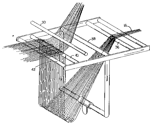
Fig. 1 is a schematic representation of commingling
apparatus according to the invention.
Fig. 2 is a perspective diagrammatic view showing air
ribboning and commingling components of the Fig. 1 apparatus.
Fig. 3 is a perspective diagrammatic view of rollers
of the Fig. 1 apparatus that are used for generating static
electricity in a yarn to provide a flat opened ribbon according
to the invention.
Structure
Referring to Figs. 1-3, there is shown commingling
apparatus 10 in use commingling polyether ether ketone (PEEK)
continuous multiple filament yarns 12 from freely rotatable
supply rolls 14 and continuous multiple filament graphite yarn
16 from freely rotatable supply roll 18. On the path of travel
of PEEK yarn 12, apparatus 10 includes gathering guide 20,
motor-driven pinch rollers 22, 24, three pretensioning bars 26,
2038542
-- 4 -- ~
five motor-driven charge-inducing rollers 28 (1/32" thick
virgin PTFE Teflon surface layers, available from DuPont,
mounted on 4" steel support rollers), and ribboning bar 30. On
the path of travel for graphite yarn 16, apparatus 10 includes
driven shaft 32, idler shaft 34, support rod 36, air curtain
element 38 (a tube connected to a source of pressurized air and
having a single row of downwardly directed holes along its
length), and support rod 40. Downstream of support rod 40 and
ribboning bar 30 are commingling bar 42, two free-wheeling
rollers 43, atomizer 44 (for spraying sizing onto the
filaments), and take-up unit 48 (including a traversing
mechanism not shown) for wrapping the commingled yarn on
take-up roll 49. Rollers 28 are electrically isolated, to
permit the static charges to build up on the yarn. Downstream
of rollers 28, ribboning bar 30, commingling bar 42, and
rollers 43 are grounded, permitting bleeding of the charges.
Pinch rolls 22, 24, driven shaft 32, and take-up unit
48 are driven by a common first drive system (not shown) to
achieve the desired velocity of yarn through the apparatus.
Rollers 28 are driven by a common second drive system (not
shown) that provides variable speed from 0 to 200 feet per
minute surface velocity, twice as fast as the typical yarn
velocity of 100 feet per minute.
In the example shown in Fig. 1, three multiple
filament yarns 12 from three rolls of PEEK (available from
Celanese under the trade designation 300/100 SP-301A PEEK) were
blended with one continuous filament graphite yarn 16 (3K
2038542
unsized carbon tow available from BASF under the trade
designation Celion) to provide the desired proportion of the
two.
Oper~tion
In operation, in general, the continuous multiple
fil~ment PEEK yarns 12 and graphite yarn 16 are separately
opened up into flat opened ribbons, the flat opened ribbons are
combined so as to have interleaving of different filaments, and
the resulting combined flat ribbon is narrowed and wound up on
the takeup roll. The graphite and PEEK yarns travel at
approximately 100 feet per minute through apparatus 10.
Discussing the processing of PEEK yarns 12 first, the
three yarns pass through and are combined at guide 20. From
there they are driven between pinch rollers 22, 24 and through
pretensioning bars 26 to rollers 28. Pretensioning bars 26
assist providing desired tension in the PEEK yarns as they
travel past and around rollers 28. The PEEK yarn cannot be
opened up by application of an air curtain and, therefore, is
opened up by generating a static charge on it through the use
of rollers 28. Rollers 28 are driven at speeds to cause
relative travel between the PEEK filaments and the Teflon
surface. Rolls 28 develop a charge that is opposite that
developed in the PEEK fibers, causing the fibers to be
attracted to the rollers, and increasing the tension in fibers
12 as they pass through the five rollers 28. (I.e., the
attraction must be overcome in pulling the yarns off of the
- 6 - 2038542
surfaces of the rollers.) Around 6000 volts is generated in
passing through rollers 28, and the electrical charge applied
to the yarn ~ilaments causes them to repel each other. Because
the cross-sectional configuration of the charged yarn leaving
rolls 28 thus tends to be circular, the open filament bundle is
drawn under ribboning bar 30 under tension to force the bundle
into the shape of a flat opened ribbon. As is seen in Fig. 3,
by the time the filaments leave ribboning bar 30, they are in
parallel configuration, and the ribbon is approximately two to
four inches wide. By varying the tension in the PEEK yarns and
the speeds of rollers 28, the charge applied to the PEEK
ilaments can be adjusted as necessary to provide the desired
opening of the individual filaments, and the desired width of
the flat ribbon that matches that of the flat ribbon of
lS graphite yarns. From ribboning bar 30, the flat opened ribbon
of PEEK yarns passes over commingling bar 42.
_ _ .
By using static-inducing rolls with controllable
speed, one can control both the charge on the yarn and the
tension, thereby controlling the separation and the width of
20 the flat opened ribbon of PEEK to provide better control of
the commingling with the opened ribbon of graphite.
_ 7 _ 20 3 8 5 4 2
Graphite yarn 16 travels from supply roll 18 between
driven shaft 32 and idler shaft 34. Driven shaft 32 is driven
at a speed equal to that of take-up roll 49 and pinch rolls 22,
24. The speed of driven shaft 32 can be adjusted if necessary
to provide the loop between support rod 36 and support rod 40.
The graphite yarn can be opened up into an open ribbon by the
application of an air curtain, because the graphite fibers are
not greatly attracted to each other. The pressurized curtain
causes the loop to extend in the direction of air flow and the
10 individual graphite filaments to separate so that the graphite
2038542
-- 8 --
yarn is in a flat opened ribbon state when it joins with the
PEEK ribbon at the commingling bar ~2.
At commingling bar 42, the opened ribbons of PEEK and
graphite are joined together, and the different filaments are
interleaved. From commingling bar 42, the combined flat opened
ribbon passes under and over free-wheeling rollers ~3 and past
atomizer 44, at which sizing is sprayed to cause the individual
filaments to tend to adhere to each other. By the time the
PEEK filaments reach atomizer 44, the charges have been bled
sufficiently to permit the fibers to be in close proximity to
each other. At atomizer 44, the commingled yarn has about a 1
1/2" width, which is reduced to about 1/8" to l/4" by the guide
of take-up unit 48, which wraps the commingled yarn on take-up
roll 49.
The commingled yarn can be stored indefinitely and
used to produce woven, drapable, reinforced thermoplastic
fabric on conventional equipment. In use in fabricating
lightweight, reinforced thermoplastic products, heat and
pressure is applied, and the PEEK flows around the reinforcing
graphite fibers and bonds the graphite fibers together. The
homogeneous nature of the commingled yarn provides intimate
contact between the individual filaments of the component PEEK
and graphite, thereby, providing improved wet out and bonding.
The process is superior to other methods of assembling such
yarns, for example, twisting and/or parallel winding, because
the individual filaments of the component yarns are more
homogeneously distributed throughout the resulting yarn.
9 2038542
Because the yarn is commingled rather than layered, the
component materials are more evenly distributed in the final
product, resulting in better blending of reinforcing graphite
fibers and resin matrix fibers, thereby producing superior
S products.
The speed of travel through apparatus 10 has an effect
on the quality of the product, in particular its homogeneity.
It was found that as the speed was increased from 20 fpm to
around 70 fpm there was not much noticeable effect on
homogeneity; at around 70 fpm, improvements in quality were
first noted, and increasing speed from 70 to over 100 fpm
resulted in further improvements in homogeneity. Continuing to
increase speed above 100 fpm should improve homogeneity even
further. It is believed that the increased speed promotes
parallel PEEK filaments during travel to the commingling bar.
One factor permitting the high speeds is that there are no
mechanical separating elements, e.g., comb teeth, which would
limit speed and potentially damage filaments.
Other Embodiments
Other embodiments of the invention are within the
scope of the following claims. For example other yarns besides
the PEEK and qraphite, e.g., polyphenylene sulfide (PPS), can
be used and commingled using apparatus 10. Also more or fewer
rolls 28 can be used to provide the charge depending on the
material, and a plurality Qf different yarns can be provided at
supply rolls 14. Also each of the yarns being commingled could
2038542
-- 10 --
be rubbed against a static charge-inducing body prior to
combining them. Also, instead of atomizer 44, sizing roll ~5
(a roller partially located in a trough containing a sizing
liquid) could be used to apply sizing to the yarns, and
materials other than Teflon can be used in the static
charge-inducing body.
Claims
What is claimed is: