Sélection de la langue

Search

Sommaire du brevet 2039163 

Énoncé de désistement de responsabilité concernant l'information provenant de tiers

Une partie des informations de ce site Web a été fournie par des sources externes. Le gouvernement du Canada n'assume aucune responsabilité concernant la précision, l'actualité ou la fiabilité des informations fournies par les sources externes. Les utilisateurs qui désirent employer cette information devraient consulter directement la source des informations. Le contenu fourni par les sources externes n'est pas assujetti aux exigences sur les langues officielles, la protection des renseignements personnels et l'accessibilité.

Disponibilité de l'Abrégé et des Revendications

L'apparition de différences dans le texte et l'image des Revendications et de l'Abrégé dépend du moment auquel le document est publié. Les textes des Revendications et de l'Abrégé sont affichés :

  • lorsque la demande peut être examinée par le public;
  • lorsque le brevet est émis (délivrance).
(12) Demande de brevet: (11) CA 2039163
(54) Titre français: SYSTEME DE DETECTION DE FUSION POUR RELAIS
(54) Titre anglais: FUSION DETECTING SYSTEM FOR RELAYS
Statut: Réputée abandonnée et au-delà du délai pour le rétablissement - en attente de la réponse à l’avis de communication rejetée
Données bibliographiques
(51) Classification internationale des brevets (CIB):
  • G01R 31/327 (2006.01)
  • H01H 47/00 (2006.01)
  • H01H 71/04 (2006.01)
  • H01H 73/12 (2006.01)
(72) Inventeurs :
  • HOSHINO, YOSHINORI (Japon)
(73) Titulaires :
  • FANUC LTD
(71) Demandeurs :
  • FANUC LTD (Japon)
(74) Agent: MARKS & CLERK
(74) Co-agent:
(45) Délivré:
(86) Date de dépôt PCT: 1990-08-29
(87) Mise à la disponibilité du public: 1991-03-02
Licence disponible: S.O.
Cédé au domaine public: S.O.
(25) Langue des documents déposés: Anglais

Traité de coopération en matière de brevets (PCT): Oui
(86) Numéro de la demande PCT: PCT/JP1990/001095
(87) Numéro de publication internationale PCT: JP1990001095
(85) Entrée nationale: 1991-04-15

(30) Données de priorité de la demande:
Numéro de la demande Pays / territoire Date
226728/1989 (Japon) 1989-09-01

Abrégés

Abrégé anglais


ABSTRACT OF THE DISCLOSURE
A fusion detecting system for relays is provided for
detecting a fusion of relay contacts. Two fully-
interlocked or semi-interlocked relays are connected in
such a manner that they operate under identical conditions,
and a fused state is detected based on the states of
signals sent from series-connected make contacts and
series-connected break contacts of the two relays. In the
case of semi-interlocked relays (R1, R2), if a make contact
(r12) is fused during a current supply to a coil, the other
contact (r22) remains in an open state or at a make-contact
side after the current supply to the coil is cut off, and
if a break contact (r11) is fused, the other contact (r21)
remains in an open state or at break-contact side after a
current is supplied to the relay coil. Accordingly, by
using two semi-interlocked relays under identical
conditions and connecting same such that the make contacts
and the break contacts are individually connected in
series, a fusion of the relays can be detected based on
signals sent from the contacts. A fusion of fully-
interlocked relays can be detected in a like manner.

Revendications

Note : Les revendications sont présentées dans la langue officielle dans laquelle elles ont été soumises.


THE EMBODIMENTS OF THE INVENTION IN WHICH AN EXCLUSIVE PROPERTY
OR PRIVILEGE IS CLAIMED ARE DEFINED AS FOLLOWS:
1. A fusion detecting system for relays for detecting
a fusion of relay contacts, comprising:
two fully-interlocked or semi-interlocked relays
connected in such a manner that the relays operate under
identical conditions, a fused state being detected based on
states of signals sent from series-connected make contacts
and series-connected break contacts of said two relays.
2. A fusion detecting system for relays according to
claim 1, wherein the detection of a fused state is effected
by a PC (programmable controller) in accordance with a
ladder program.
3. A fusion detecting system for relays according to
claim 1, wherein said relays comprise relays which output
an emergency stop signal.
4. A fusion detecting system for relays according to
claim 1, wherein said relays comprise relays which output
an interlock signal of a machine tool.

Description

Note : Les descriptions sont présentées dans la langue officielle dans laquelle elles ont été soumises.

~03'31~:i3
- 1 - .
D E S C R I P T I O N
FUSION DETECTING SYSTEM FOR RELAYS
Technical Field
This invention relates to a fusion detecting system
for relays for detecting a fusion of relay contacts, and
more particularly, to a fusion detecting system for relays
for detecting a fusion thereof by using semi-interlocked or
fully-interlocked relays.
sackground Art
Contacts of relays, magnets, or the like are sometimes
fused together by an extreme current overload or
contamination due to long use, and if these relays or ;
magnets are used to produce a safety signal for a PC
(programmable controller), etc. which controls a machine
tool, for example, an emergency stop signal, or an
interlock signal associated with a splash guard of the
machine tool, the operator may be exposed to unexpected
danger. Accordingly, to avoid this danger, semi-
interlocked or fully-interlocked relays are used.
In semi-interlocked relays, if a make contact is fused
during a current supply to the coil, the other contact is
held in an open state or at a make-contact side after the
current supply to the coil is cut off. On the other hand,
if a break contact is fused, the other contact is held in
:
- ; ., .- :
., , i : , . .
. ' : :' .,: ' ' - ; . '~ . :': - '

2039163
-- 2 --
an open state or at a break-contact side afte~ a current
supply to the relay coil is started.
In fully-interlocked relays, if a make contact is fused
during a current supply to the coil, the other contact is
held in a make-contact state after the current supply to
the coil is cut off, and if a break contact is fused, the
other contact is held in a break-contact state after a
current supply to the relay coil is started.
Nevertheless, even when these relays are used, danger
cannot be avoided if the fused contact is used to produce
an emergency stop signal or the like.
Usually, the movement of the contacts of these relays,
etc., is too minute to be observed with the naked eye, and
since the relays are generally housed in the casing of a
control device, the movement or non-movement of a contact
cannot be determined from the outside.
Disclosure of the Invention
This invention has been created in view of the above
circumstances, and an object thereof is to provide a fusion
detecting system for relays by which a fusion of relays can
be reliably detected.
To achieve the above object, according to this
invention, there is provided a fusion detecting system for
relays wherein two fully-interlocked or semi-interlocked ;
relays are connected in such a manner that they operate
under identical conditions, and a fused state is detected
' ' .' ' ' ' ' '. . , . ~ :, ' . ,' , . I , ! . , .
' ' " , . ' ,`' ' ~ ' . ',' ,

2039163
based on the states of signals sent from series-connected
make contacts and series-connected break contacts of the
two relays.
In semi-interlocked relays, if a make contact is fused
during a current supply to the coil, the other contact is
held in an open state or at a make-contact side after the
current supply to the coil is cut off, and if a break
contact is fused, the other contact is held in an open
state or at a break-contact side after a current is
supplied to the relay coil.
In fully-interlocked relays, if a make contact is
fused during a current supply to the coil, the other
contact is held in a make-contact state after the current
supply to the coil is cut off; if a break contact is fused,
the other contact is held in a break-contact state after a -
current is supplied to the relay coil.
Accordingly, two semi-interlocked or fully-interlocked
relays are used under identical conditions, the make
contacts and break contacts of the relays are individually
connected in series, and signals sent therethrough are
checked to thereby detect a fusion of the relays.
~'
Brief Description of the Drawings
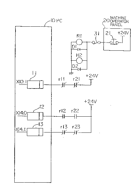
Fig. 1 is a circuit diagram illustrating a relay
checking system according to this invention;
Fig. 2 is a diagram illustrating a ladder program for
detecting a fusion of relays; and
- , .
.
- . . .
.

X0~9163
-- 4
Fig. 3 is a diagram of a logic table us~d for
detecting a fusion of relays.
Best Mode of Carrying Out the Invention
One embodiment of this invention will be described
with reference to the drawings.
Figure 1 is a circuit diagram showing a relay checking
system according to this invention, in which a PC
(programmable controller) 10 includes receivers 11, 12 and
13 for receiving signals input thereto from outside, and
processes these signals in accordance with a sequence
program, to provide a signal for controlling a machine.
These control operations are carried out by a
microprocessor, but elements other than the receivers are
omitted from the figure for simplicity.
An emergency stop button 21 of a machine operator
panel 20 is connected to relays R1 and R2 through a contact
31. The relays R1 and R2 are connected in parallel with
diodes D1 and D2, respectively. The contact 31 serves as a
signal contact for an emergency stop, for example, a
contact actuated when the machine r~aches a stro~e end. In
practice, a plurality of emergency stop conditions are
included and a large number of contacts are connected in
series, but the contact 31 alone is illustrated in the
figure, for simplicity.
Semi-interlocked relays or fully-interlocked relays
can be used for the relays R1 and R2; here it is assumed
:,:

203~ 3
-- 5
that semi-interlocked relays are used. A break contact r11
of the relay R1 and a break contact r21 of the relay R2 are ;
connected in series, and are connected to the receiver 11.
Namely, when the emergency stop button 21 is pressed, the
relays R1 and R2 are turned off with the break contacts r11
and rl2 thereof open, and thus an emergency stop signal is ;
input to the receiver 11 of the PC 10, whereby an emergency
stop state is established and an outside operation is
interrupted.
The receiver 12 is connected in series with make
contacts r12 and r22 of the relays R1 and R2, and the
receiver 13 is connected in series with break contacts r13
and r23 of the relays R1 and R2.
The letters and numbers on the left of the receivers .
11, 12 and 13 represent addresses for the respective input
signals.
Figure 2 shows a ladder program for detecting a fusion
of relays, wherein a logical sum of the input signal
(X14.0) to the receiver 12 and the input signal (X14.1) to
the rece~ver 13 through the break contacts is connected to
a coil (R640.0); when a fusion of the contacts occurs, the
coil (R640.0) is made "1."
Figures 3 is a diagram of a logic table for detecting
a fusion of relays. In a normal state, when the emergency
stop button 21 (indicated in Fig. 3 as E button) is off,
the make contacts r12 and r22 are on ("1"), the input
signal X14.0 is on and a negative signal thereof (indicated
, , , . . , . , , - . . . :
- : ,
.

26~391~
-- 6
by "*" in the figure) is "0," when the break contacts r13
and r23 are off ("0"), the input signal X14.1 is "0" and a
negative signal thereof *X14.1 is "1," and accordingly, a
signal (R640.0) which indicates a fusion of the contacts is
"G."
~ lso when the emergency stop button 21 is on, the
signal (R640.0) is "0."
If a fusion of the break contact of the relay (R1)
occurs while the emergency stop button 21 is off, the
emergency stop button 21 is made on and the make contact
r12 of the relay (R1), which originally should be on, is
made off ("0"), whereby the signal (R640.0) becomes "1" and
thus the fusion state is detected.
Similarly, if a fusion of the make contact of the
relay (R1) occurs while the emergency stop button 21 is on,
the emergency stop button 21 is made off and the break
contact r13 of the relay (R1), which originally should be
on, is made off ("0"). Accordingly, the signal (R640.0)
becomes "1" and the fusion state can be detected.
Therefore, as de~cribed above, a fusion of the
contacts can be reliably detected.
- In the above example, semi-interlocked relays are
mentioned, but these can be replaced by fully-interlocked
relays.
Further, ln the above description, a signal of the
emergency stop button is exemplified, but the foregoing
applies to the use of any other signals relating to safety,

20391~ ,
- 7 -
such as an interlock signal of a machine tool which is used
to interlock the control device when the splash guard of
the machine tool is not closed.
As described above, according to this invention, a
fusion of the relay contacts is detected by using semi-
interlocked or fully-interlocked relays, whereby a fusion of
the relays can be reliably detected and the reliability of
the machine tool, etc., is improved.
,:
'
, ' :
:
- . : :. .. .. . : .
. , : . . . ., : .. ,
,
.

Dessin représentatif
Une figure unique qui représente un dessin illustrant l'invention.
États administratifs

2024-08-01 : Dans le cadre de la transition vers les Brevets de nouvelle génération (BNG), la base de données sur les brevets canadiens (BDBC) contient désormais un Historique d'événement plus détaillé, qui reproduit le Journal des événements de notre nouvelle solution interne.

Veuillez noter que les événements débutant par « Inactive : » se réfèrent à des événements qui ne sont plus utilisés dans notre nouvelle solution interne.

Pour une meilleure compréhension de l'état de la demande ou brevet qui figure sur cette page, la rubrique Mise en garde , et les descriptions de Brevet , Historique d'événement , Taxes périodiques et Historique des paiements devraient être consultées.

Historique d'événement

Description Date
Inactive : CIB désactivée 2011-07-26
Inactive : CIB de MCD 2006-03-11
Inactive : CIB dérivée en 1re pos. est < 2006-03-11
Demande non rétablie avant l'échéance 1993-02-28
Le délai pour l'annulation est expiré 1993-02-28
Inactive : Demande ad hoc documentée 1992-08-31
Réputée abandonnée - omission de répondre à un avis sur les taxes pour le maintien en état 1992-08-31
Demande publiée (accessible au public) 1991-03-02

Historique d'abandonnement

Date d'abandonnement Raison Date de rétablissement
1992-08-31
Titulaires au dossier

Les titulaires actuels et antérieures au dossier sont affichés en ordre alphabétique.

Titulaires actuels au dossier
FANUC LTD
Titulaires antérieures au dossier
YOSHINORI HOSHINO
Les propriétaires antérieurs qui ne figurent pas dans la liste des « Propriétaires au dossier » apparaîtront dans d'autres documents au dossier.
Documents

Pour visionner les fichiers sélectionnés, entrer le code reCAPTCHA :


Pour visualiser une image, cliquer sur un lien dans la colonne description du document (Temporairement non-disponible). Pour télécharger l'image (les images), cliquer l'une ou plusieurs cases à cocher dans la première colonne et ensuite cliquer sur le bouton "Télécharger sélection en format PDF (archive Zip)" ou le bouton "Télécharger sélection (en un fichier PDF fusionné)".

Liste des documents de brevet publiés et non publiés sur la BDBC .

Si vous avez des difficultés à accéder au contenu, veuillez communiquer avec le Centre de services à la clientèle au 1-866-997-1936, ou envoyer un courriel au Centre de service à la clientèle de l'OPIC.

({010=Tous les documents, 020=Au moment du dépôt, 030=Au moment de la mise à la disponibilité du public, 040=À la délivrance, 050=Examen, 060=Correspondance reçue, 070=Divers, 080=Correspondance envoyée, 090=Paiement})


Description du
Document 
Date
(aaaa-mm-jj) 
Nombre de pages   Taille de l'image (Ko) 
Abrégé 1991-03-01 1 45
Dessins 1991-03-01 3 51
Revendications 1991-03-01 1 29
Description 1991-03-01 7 242
Dessin représentatif 1999-07-29 1 11