Sélection de la langue

Search

Sommaire du brevet 2039877 

Énoncé de désistement de responsabilité concernant l'information provenant de tiers

Une partie des informations de ce site Web a été fournie par des sources externes. Le gouvernement du Canada n'assume aucune responsabilité concernant la précision, l'actualité ou la fiabilité des informations fournies par les sources externes. Les utilisateurs qui désirent employer cette information devraient consulter directement la source des informations. Le contenu fourni par les sources externes n'est pas assujetti aux exigences sur les langues officielles, la protection des renseignements personnels et l'accessibilité.

Disponibilité de l'Abrégé et des Revendications

L'apparition de différences dans le texte et l'image des Revendications et de l'Abrégé dépend du moment auquel le document est publié. Les textes des Revendications et de l'Abrégé sont affichés :

  • lorsque la demande peut être examinée par le public;
  • lorsque le brevet est émis (délivrance).
(12) Demande de brevet: (11) CA 2039877
(54) Titre français: APPAREIL D'ISOLATION ELECTRIQUE
(54) Titre anglais: ELECTRICAL INSULATION APPARATUS
Statut: Réputée abandonnée et au-delà du délai pour le rétablissement - en attente de la réponse à l’avis de communication rejetée
Données bibliographiques
(51) Classification internationale des brevets (CIB):
  • H01B 17/58 (2006.01)
  • H02G 15/013 (2006.01)
  • H02G 15/04 (2006.01)
(72) Inventeurs :
  • MACEY, LAURENCE D. (Australie)
(73) Titulaires :
  • CROUSE-HINDS (AUSTRALIA) PTY LTD.
  • COOPER INDUSTRIES, INC.
(71) Demandeurs :
  • CROUSE-HINDS (AUSTRALIA) PTY LTD. (Australie)
  • COOPER INDUSTRIES, INC. (Etats-Unis d'Amérique)
(74) Agent: SMART & BIGGAR LP
(74) Co-agent:
(45) Délivré:
(22) Date de dépôt: 1991-04-05
(41) Mise à la disponibilité du public: 1991-10-06
Licence disponible: S.O.
Cédé au domaine public: S.O.
(25) Langue des documents déposés: Anglais

Traité de coopération en matière de brevets (PCT): Non

(30) Données de priorité de la demande:
Numéro de la demande Pays / territoire Date
PJ9495 (Australie) 1990-04-05

Abrégés

Abrégé anglais


ABSTRACT
Electrical insulation apparatus namely a water resistant gland for
the protected connection at an electrical cable. The gland is shaped for
location around an electrical cable and includes a moisture impervious
outer body and a pair of annular grommets located within the outer body.
The grommets are arranged to contact and surround the cable. The grommets
are of resilient material such as neoprene and include steel plates of
annular construction located at either end of the neoprene body. A
mechanism is provided to force the grommets into contact either with each
other or with a cable protective armouring portion located between the
grommets.
BJG/1294D
-1-

Revendications

Note : Les revendications sont présentées dans la langue officielle dans laquelle elles ont été soumises.


The embodiments of the invention in which an exclusive property or
vilege is claimed are defined as follows:
1. A water (or other moisture) resistant gland adapted for location
around an electrical cable, said gland comprising:
a solid moisture impervious outer body;
a pair of substantially annular grommets located within said body and
adapted to contact and surround an electrical cable; and
means adapted to force said grommets into contact either with each
other or with a cable protective armouring portion located between said
grommets.
2. A gland as claimed in claim 1, wherein the means adapted to
force the grommets either together or into contact with the cable
protective armouring comprises:
a grommet pressure plate; and
means adapted to attach said plate to the outer body.
3. A gland as claimed in claim 2, where the attachment means
comprises:
a plurality of internally threaded recesses provided in the outer
body;
a plurality of screws; and
a corresponding plurality of holes provided in the peripheral portion
of the grommet pressure plate;
wherein the screws are adapted to be inserted through the plurality
of holes and mate with the internal threads provided in the recesses, so
allowing the pressure plate to apply pressure to the grommets when the
screws are tightened.
4. A gland as claimed in claims 2 or 3, wherein the pressure plate
is provided with a plurality of filling apertures; said filling apertures
being adapted to allow filling with a compound such as silicon rubber,
pitch, or other approved filling compound.
5. A gland as claimed in any one of the previous claims, wherein
the body is provided with earthing terminals, said earthing terminals being
adapted to be attached to earth screens provided in the cable.
6. A gland as claimed in any one of the previous claims, where the
grommets are formed of resilient material.
7. A gland as claimed in any one of the previous claims, where said
grommets are formed of neoprene.
RLF/1095h -5-

8. A gland as claimed in any one of the previous claims, wherein
said grommets are provided with ridges on their internal cylindrical
surfaces, said ridges being adapted to grip and seal the outer or inner
surface of the cable.
9. A gland as claimed in any one of the previous claims, wherein
the outside body is provided with a flange, said flange being provided with
a plurality of holes, said holes being adapted to allow the flange to be
fastened to an apparatus which receives the cable by means of screws.
10. A gland as claimed in any one of claims 1 to 8, wherein the body
is provided with a flange, said flange being adapted to be welded to an
apparatus which receives the cable from the gland.
11. A gland as claimed in any one of claims 1 to 8, wherein the
gland is provided with a threaded outside bore, said threaded outside bore
being adapted to be screwed into a corresponding threaded recess provided
in a device which receives the cable from the gland.
12. A gland substantially as hereinbefore described with reference
to the accompanying drawings.
RLF/1095h -6-

Description

Note : Les descriptions sont présentées dans la langue officielle dans laquelle elles ont été soumises.

2039877
ELECTRICAL INSULATION APPARATUS
This invention relates to an electrical cable connection apparatus
and more particularly to a water resistant gland for the protected
connection of a cable.
The use of electricity is incompatible with moisture if molsture of
any description particularly water vapour or water itself should come into
contact with wires adapted to carry electricity short circuiting results
and the consequences may be fire exploslon and perhaps death of persons in
the vicinity. Particularly is this so in underground mining operatlons
which are conducted ~n a damp environment and where very substantial
currents and/or voltages are utilized.
Various methods for prevention of moisture incurslon into electrical
wiring have been proposed in the past but each has had its deficiencies.
There is a considerable need for a gland which may be rel~ed upon to
prevent ingress of moisture to the wiring of electrlcal cables and into the
interstices of the cable ltself.
It ls an ob~ect of thls lnvention to provlde a water (or other
moisture) reslstant gland whlch may be relled upon to prevent ingress of
molsture to electrical wirlng ln ronventlonal wiring arrangements.
Thls lnventlon ln one broad form provldes a water (or other moisture)
reslstant gland adapted for location around an electrlcal cable said gland
comprlsing a solld moisture impervious outer body a palr of substantlally
annular grommets located wlthin sald body and adapted to contact and
surround an electrical cable and means for forcing said grommets into
contact either w~th each other or with a cable protect~ve armouring portion
located between said grommets.
It is preferred that the grommets be formed of reslllent materlal and
neoprene ls one of the most preferred materlals.
The outslde body should be adapted for connection to the transformer
cover or other apparatus ln relatlon to whlch the gland of this lnventlon
ls utlllzed. For example the outside body may be provided with a flange
through whlch a series of screws mlght be located to connect the flange to
a tranformer connectlon box cover. Alternatlvely the flange may be of
steel adapted to be welded to such transformer connectlon box cover. Again
the body may not be provided with a flange but merely with a threaded
outside bore adapted to be screwed ~nto the dev~ce to which the cable is
lntroduced through the gland.
RLF/109Sh - 2 -
. . , , ~ ,, ~ .

Z039877
Where the gland of this invention is utilized with high voltage three
phase cabling earthing terminals may be provided for each of the earth
screens surrounding the three phase cables.
The preferred means of forcing the grommets either together or into
contact with the aforesaid cable protective armouring resides in the
provision of a grommet pressure plate at the end of the body portion of the
gland opposite from the end thereof adapted for attachment to the
transformer cover or other apparatus to which the gland must be attached.
The body preferably incorporates an internally threaded female portion into
which a ser~es of screws inserted through the peripheral portion of the
grommet pressure plate may be screwed to tighten the pressure plate against
the end gland. The pressure plate may be provided with a plurality of
filling apertures. These apertures might be filled with a compound such
as silicon rubber or pitch or other approved filling compound.
By way of example only one embodiment of apparatus according to this
invention will now be described with reference to the accompanying drawings
wherein:
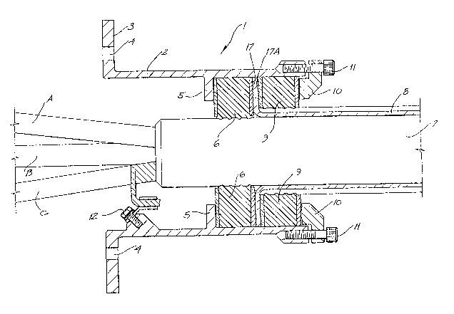
Fig. 1 is a section of a typical assembly of a gland according to
this invention disposed on a three phase electrical cable;
Fig. 2 is a section of the body of the gland of Fig. 1 depicted in
relation to its mounting flange;
Fig. 3 depicts on the right of the draw~ng an end view and on the
left of the drawing a section of a grommet utilizing the assembly of
fig. l; and
Fig. 4 depicts front and rear views and section of the grommet
pressure plate utilized as part of the apparatus of fig. 1.
In the drawings gland shown generally at 1 comprises impervious body
portion 2 preferably of metal such as bronze. Body 2 is provided in this
embodiment with a mounting flange 3 through apertures 4 of which screws
may be inserted to mount gland 1 to the body of a transformer or the like.
Body 2 includes annular rib S aga~nst which first grommet 6 is
disposed. In this embodiment gland 1 ~s shown d~sposed around three phase
cable 7 the protective armouring 8 of which is stripped from cable 7 and
clamped between first annular flange 6 and second annular flange 9.
Grommet pressure plate 10 is located at the rear of body 2 and
screws 11 are provided to force pressure plate 10 aga~nst grommet 9 until
gland 1 is secured in moisture proof manner around cable 7.
RLf/109Sh _3_
. ..
~" ' ' ' ` ~ ;. '

Z039877
Earthing terminals 12 are provided in conjunction with this
embodiment of gland 1, there being one earthing terminal for each of the
three phase cables A, B, & C.
Screws 11 are inserted through apertures 13 in grommet pressure
plate 10 and into suitably threaded female receptacles 14 in body 2 of
gland 1.
Grommets 6 and 9 comprise steel plate outer members 16 and 17 between
which are located neoprene members 18. Steel plate 17 is notched as is
complementary steel plate 17A of grommet 9. Both grommets 6 and 9 are
provided with neoprene ridges 19 to grip and seal the outer surface of
cable 7.
It will be appreciated that, in the embod~ment depicted and described
herein, grommet 9 ~s of sl~ghtly greater internal radius than grommet 6 in
order that cable protect~ve armouring 8 and ~ts outer cover might be
accommodated. However, where a gland of th~s invention ~s ut~lized with
cable whlch does not lncorporate an outer protect~ve armour~ng, grommets 6
and 9 w~ll be of ~dent~cal inner and outer radius.
It w~ll be appreciated that a gland in accordance with this
invention, might be prov~ded in such dimensions as to accommodate cables
from 20 mm to 200 mm outside dlameter. Further, the mounting flange
attachment system may be var~ed in s~ze or format to suit various
appl~cat~ons.
RLF/1095h
'. ' ' '~ . ,A
. : . :'': ' '.,'. '
~ ' ' ' ' ~,"' ' "" '' ' ' .

Dessin représentatif
Une figure unique qui représente un dessin illustrant l'invention.
États administratifs

2024-08-01 : Dans le cadre de la transition vers les Brevets de nouvelle génération (BNG), la base de données sur les brevets canadiens (BDBC) contient désormais un Historique d'événement plus détaillé, qui reproduit le Journal des événements de notre nouvelle solution interne.

Veuillez noter que les événements débutant par « Inactive : » se réfèrent à des événements qui ne sont plus utilisés dans notre nouvelle solution interne.

Pour une meilleure compréhension de l'état de la demande ou brevet qui figure sur cette page, la rubrique Mise en garde , et les descriptions de Brevet , Historique d'événement , Taxes périodiques et Historique des paiements devraient être consultées.

Historique d'événement

Description Date
Inactive : CIB de MCD 2006-03-11
Le délai pour l'annulation est expiré 1994-10-05
Demande non rétablie avant l'échéance 1994-10-05
Réputée abandonnée - omission de répondre à un avis sur les taxes pour le maintien en état 1994-04-05
Inactive : Demande ad hoc documentée 1994-04-05
Demande publiée (accessible au public) 1991-10-06

Historique d'abandonnement

Date d'abandonnement Raison Date de rétablissement
1994-04-05
Titulaires au dossier

Les titulaires actuels et antérieures au dossier sont affichés en ordre alphabétique.

Titulaires actuels au dossier
CROUSE-HINDS (AUSTRALIA) PTY LTD.
COOPER INDUSTRIES, INC.
Titulaires antérieures au dossier
LAURENCE D. MACEY
Les propriétaires antérieurs qui ne figurent pas dans la liste des « Propriétaires au dossier » apparaîtront dans d'autres documents au dossier.
Documents

Pour visionner les fichiers sélectionnés, entrer le code reCAPTCHA :


Pour visualiser une image, cliquer sur un lien dans la colonne description du document. Pour télécharger l'image (les images), cliquer l'une ou plusieurs cases à cocher dans la première colonne et ensuite cliquer sur le bouton "Télécharger sélection en format PDF (archive Zip)" ou le bouton "Télécharger sélection (en un fichier PDF fusionné)".

Liste des documents de brevet publiés et non publiés sur la BDBC .

Si vous avez des difficultés à accéder au contenu, veuillez communiquer avec le Centre de services à la clientèle au 1-866-997-1936, ou envoyer un courriel au Centre de service à la clientèle de l'OPIC.


Description du
Document 
Date
(aaaa-mm-jj) 
Nombre de pages   Taille de l'image (Ko) 
Abrégé 1991-10-05 1 17
Dessins 1991-10-05 4 93
Revendications 1991-10-05 2 59
Description 1991-10-05 3 117
Dessin représentatif 1999-07-18 1 22