Note : Les descriptions sont présentées dans la langue officielle dans laquelle elles ont été soumises.
20402~3
-
Mechanical change gear transmissions (i.e.
utilizing positive jaw clutches to engage and disengage
desired gear ratios) of the automatic, semi-automatic
and manual types which utilize upshift brakes, also
called "inertia brakes" and "input shaft brakes", to
quickly retard the rotational speed of gearing and
clutch members associated with the transmission input
shaft to provide quicker synchronization during an
upshift (as compared to relying on engine rotational
speed decay) are well known in the prior art.
Examples of such prior art transmissions may
be seen by reference to United States Patents Nos.
4,873,637; 4,852,006; 4,676,115; 4,648,290;
4,614,126; 4,361,060 and 3,478,851.
In manual transmissions, the upshift brake is
typically operator actuated by a control switch, often a
normally open switch closed upon full overtravel or
bottoming of the manual clutch pedal, which selectively
causes a retarding force to be applied directly to the
input shaft or to gearing or shafts constantly drivingly
20~33
engaged to the input shaft. Typically, the input shaft
or upshift brake will include a gear constantly meshed
with a transmission gear driven by the input shaft and a
selectively engaged friction clutch pack is provided to
frictionally ground the upshift brake gear to the
transmission housing. Typically, the friction clutch
pack is engaged/released by means of a hydraulic or
pneumatic piston/cylinder assembly.
While the prior art upshift brakes are
generally well received and commercially successful,
they are not totally satisfactory as the upshift brake
housings were subject to axial and/or torque loading
which, due to the cyclical loading, required excessively
costly and/or weighty robust housing designs and/or
could result in housing or brake assembly fatigue and/or
failure.
SU~MARY OF TH~ INVENTION
In accordance with the present invention, the
drawbacks of the prior art have been minimized or
overcome by the provision of an upshift brake structure
which reduces cyclical a~ial and/or torque loading on
the upshift brake housing. This allows a smaller, more
easily and universally fitted brake assembly housing to
be used and/or allows the housing to be cast from an
aluminum alloy for reduced weight.
The above is accomplished by providing an
upshift brake wherein the stator member (carrying the
fixed friction discs) and the actuating piston/cylinder
assembly are axially clamped by a through bolt,
independent of the housing, to minimize or isolate the
housing end walls from cyclical axial loading.
Further, the stator member is tightly clamped to the
housing whereby torque is transferred primarily by a
20~0233
-- 3
frictional coupling rather than by cooperating flat surfaces
machined on the housing and stator member which, due to
required manufacturing tolerances, can result in end loading
with resultant high stress.
Accordingly, the present invention provides a new and
improved upshift brake structure which reduces or minimizes
cyclical axial and/or torsional loading on the upshift brake
housing.
Specifically, there is provided an upshift brake for a
mechanical change gear transmission having input gearing and a
housing, said upshift brake comprising a brake housing
defining a pair of generally parallel axially spaced end walls
cantilever mounted to and extending from a base portion, a
gear member rotatably supported.by one of said end walls and
constantly meshed with one of the gears of the input gearing
of said transmission, a stator member rotationally and axially
fixed to one of said end walls, said stator member axially
fixed to and rotationally supporting said gear member, a
friction brake disc pack comprising at least one first disc
fixed to said gear and one second disc member rotationally
fixed to said stator, and a fluid cylinder/piston assembly
having a first axially contracted position corresponding to
disengagement of said brake and a second axially expanded
position corresponding to engagement of said brake, said
piston/cylinder assembly including a reaction member axially
fixed relative to said brake housing, said upshift brake
characterized by:
said cylinder/piston assembly additionally comprises a
support member axially movable relative to said housing and
axially fixed relative to said reaction member, said support
member being generally coaxial with said stator member, and
- means for axially clamping said stator member to said
axially fixed reaction member.
This and other advantages of the present invention will
become apparent from a reading of the description of the
preferred embodiment taken in connection with the attached
drawings.
~'
- 3a - i20~0~33
DESCRIPTION OF THE DRAWINGS
Figure 1 is a perspective view, partially in section, of
the upshift brake of the present invention.
Figure 2 is a plan view of the upshift brake as the
present invention.
Figure 3 is a plan view of a typical prior art upshift
brake.
Figure 4 is a schematic illustration of a mechanical
transmission system utilizing an upshift brake.
DESCRIPTION OF THE PREFERRED EMBODIMENT
Certain terminology will be used in the following
description for convenience and reference only and will not be
limiting. The words "upwardly", "downwardly", "rightwardly",
and "leftwardly" will designate directions in the drawings to
which reference is made. The words "forward" and "rearward"
will refer respectively to the front and rear end of the
transmission as same is conventionally mounted in a vehicle,
being respectfully the left and right sides of
~ 4 ~ 2 0 4 0~ 3 3
the transmission as illustrated in Figure 4. The words
"inwardly" and outwardly will refer to directions
toward and away from, respectfully, geometric center of
the device and/or designated part thereof. Said
terminology will refer to the words above specifically
mentioned, and to the derivatives thereof and words of
similar import.
Referring to Figure 4, a simple mechanical
transmission 10 of the type utilizing an input shaft
brake B is schematically illustrated. While
transmission 10 is a nonsynchronized simple
transmission, it is understood that upshift brakes are
also advantageously utilized with compound
transmissions, synchronized transmissions and/or blocked
transmissions. Esamples of such transmissions may be
seen by reference to United States Patents Nos.
4,635,109; ~,754,665; 4,432,251 and/or 3,105,395,
Transmission 10 includes an input shaft 18
supported adjacent its forward end by a bearing 20 and
provided with an input gear 22 nonrotatably connected
thereto, as by splines. The input gear 22
simultaneously drives a plurality of main section
countershafts at equal speeds. In the illustrated
embodiment, the transmission is provided with two main
section countershafts, 24 and 26, disposed on
diametrically opposite sides of the main shaft 28, which
main shaft also defines the output shaft and is
coaxially aligned with the input shaft 18.
The input shaft 18 is normally driven in one
direction only by a prime mover, such as a throttle
controlled diesel engine E through a selectively
operated, normally engaged, friction master clutch C.
A
~ . - 5 - 2~0233
-
Clutch C may be selectively disengaged by use of a
pedal P as is known in the prior art. Preferably, as
will be described in greater detail below, full
depression or overtravel of clutch pedal P will operate
a switch S for control of an input shaft brake B.
Each of the main section countershafts, 24 and
26, is provided with an identical grouping of
countershaft gears, 36, 38, 40, 42 and 44 thereon.
Which groupings form pairs of gears such as a pair of
gears 36, of identical size and number of teeth and
disposed on diametrically opposite sides of the main
shaft 28. A plurality of main shaft drive gears 46, 48,
S0 and 52 surround the main shaft 28 and are selectively
clutchable thereto, one at a time, by sliding clutch
collars as is well known in the art.
The main shaft gears 46, 48 and 50 encircle the
main shaft 28 and are in continuous meshing engagement
with, and are floatingly supported by, the diametrically
opposed pairs of countershaft gears 38, 40 and 42,
respectively, which mounting means and the special
advantages resulting therefrom are e~plained in greater
detail in United States Patent Nos. 3,105,395 and
3,335,616,
The main shaft gear 52 is the reverse gear and
is in continuous meshing engagement with a pair of
countershaft gears 44 by means of conventional
intermediate idler gears (not shown). The forwardmost
countershaft gears 36 are continuously meshed with and
driven by the input gear 22 for causing simultaneous
rotation of the countershafts 24 and 26 whatever input
shaft is rotata~ly driven.
The main shaft gears 46, 48, 50 and 52, and
main section countershaft gears 36, 38, 40, 42 and 44,
A
2~40233
and the idler gears, are all constantly meshed with and
driven by the input gear 22 and thus, in combination,
form the input gearing of transmission 10.
Sliding clutch collars 56, 58 and 60 are
splined to main shaft 28 for axial movement relative
thereto and rotation therewith as is well known in the
art. Sliding clutch 56 is axially slidable by means of
shift fork 62 to clutch gear 52 to the main shaft.
Sliding clutch 58 is axially slidable by means of shift
fork 64 to clutch idler gear 50 or 48 to the main
shaft. Sliding clutch 60 is a~ially slidable by means
of shift fork 60 to clutch gear 46 to the main shaft or
to clutch the input gear 22 (and thus the input shaft
18) to the main shaft. Shift fork 62, 64 and 66 are
attached to shift bars, or shift rails, (not shown) as
is well known in the prior art.
By way of example in an upshift of transmission
10 from third gear (gear 46 clutched to main shaft 28)
to fourth gear (input gear 22 clutched to main shaft 28)
it is necessary to disengage gear 46 from the main shaft
28 and then as the rotational speed of main shaft 28
will remain substantially fixed during the shift
transient, it is necessary to decrease the speed of
input gear 22. As it may be undesirable to rely on the
natural decay of the engine to slow the input shaft 18
and input gear 22, it is often desirable to utilize the
input brake B for more rapid upshifts, as is well known
in the prior art. Typically, to actuate the upshift
brake B, the master clutch pedal P is fully depressed
until a switch S is contacted which will actuate the
input shaft brake B for additional, more rapid
retardation of the transmission input gearing. In the
embodiment illustrated, countershaft gear 40 on
countershaft 26 is constantly meshed with an input shaft
20~02~3
brake gear 68 which may be selectively frictionally
grounded by means of the input shaft brake B for more
rapid retardation of the input gearing of transmission
10 for quicker upshift synchronization.
A typical prior art upshift brake 70 is
illustrated in Figure 3. The upshift or input shaft
brake 70 includes a support housing 72 which is
mountable to the housing of transmission 10. A stator
member 74 is rotationally fised to the housing 72 by
means of a keeper member 76 having machined surfaces 78
and 80 which interact with complimentary flat surfaces
82 and 84 provided on the stator member and on the
housing, respectively. A bolt 86 is provided for
axially retaining the stator member and the keeper
member in the bore 88 of the housing 72. A tab washer
90 interacts with the head of bolt 86 to rotationally
fi~ the bolt relative to the stator and the housing.
The upshift brake gear 68 is rotatably
supported on the stator by means of ball bearings 92
which are axially positioned between the shoulder 94
defined by the stator and the spacer 96 interposed the
bearings and the inner surface of the lefthand in wall
of housing 72. The input shaft gear 68 includes an
inwardly e~tending annular sleeve 98 a plurality of
carrying radially inwardly extending friction discs 100
which are interdigitated with radially outwardly
e~tending clutch discs 102 carried by the stator 94 to
define a selectively engageable clutch disc pack 104.
A pressurized fluid piston/cylinder assembly
106 is provided for selective engagement and
disengagement of the friction clutch disc pack 104. The
piston/cylinder assembly 106 includes a central support
member 108 axially fixed to the righthand end wall 110
of the housing 72 by means of threaded fasteners 112, an
20~0233
axially fixed piston member 114 supported by the annular
member 108 and an axially movable cylinder member 116
slidingly supported on a fixed piston member 114. The
cylinder member 116 is biased axially rightwardly by
means of a return spring 118 and includes engagement
surfaces 120 for applying an axial compressor force to
clutch disc pack 104. The support member 108 defines a
fluid passage 122 for cooperation with a fluid passage
124 defined in the housing 72.
Briefly, as is known, the upshift or input
shaft brake 70 is normally disengaged as the return
spring 118 biases the cylinder member 116 axially
rightwardly. To engage the brake 70 pressurized fluid
is introduced via passages 122 and 124 to chamber 126
which will cause the cylinder member 116 to move axially
leftwardly to engage the clutch disc pack 104 thereby
applying a retarding frictional drag to gear 68 and the
input gearing of transmission 10. As may be seen, upon
pressurization of chamber 126, an asial separation force
will be applied to righthand end wall 110 and lefthand
end wall 128 of the upshift brake housing 72 which axial
loading, due to the cyclical loading, will require an
e~cessively costly and/or weighty robust housing design
and/or can resolve in housing fatigue and/or failure.
Additionally, upon actuation of the input brake 70, a
torque force will be applied to the stator member 74 by
means of the clutch discs 102 which torque will be
reacted by the machined flat surfaces 78, 80, 82 and 84
to the housing 72. Due to the manufacturing tolerances
and clearances between the machine flat surfaces, end
loading can occur which will result in high stress to
the cooperating flat surfaces.
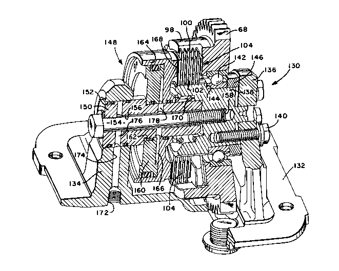
The improved upshift or input shaft brake 130
of the present invention may be seen by reference to
2040233
Figures 1 and 2. As with the prior art upshift brake 70
described above, the upshift brake 130 of the present
invention includes an upshift brake gear 68 which is
constantly meshed with the input gearing of transmission
10 and includes a housing 132 mountable to the
transmission housing of transmission 10.
The upshift brake housing 132 defines a
cantilevered righthand end wall 134 and a cantilevered
lefthand end wall 136. A stator member 138 is axially
and rotationally fixed to the lefthand end wall 136 of
the housing by means of a plurality of through bolts
140. The upshift brake gear 68 is rotationally
supported on an outer diameter surface of stator 138 by
means of a bearinq such as roller bearing 142 which is
asially positioned between a shoulder 144 defined by the
stator 138 and a spacer member 146 interposed the
. lefthand end wall 136 of housing 132 and the bearing
142. The upshift brake gear 68 includes an inwardly
extending annular sleeve 98 carrying a plurality of
radially inwardly extending friction discs 100 which are
interdigitated with radially outwardly e~tending clutch
discs 102 carried by the stator 138 to define a
selectively engageable clutch or brake disc pack 104.
A pressurized fluid actuated piston/cylinder
assembly 148 is provided for selective engagement and
disengagement of the clutch disc pack 104. A central
support member 150 is received within an enlarged
through bore 152 provided in the rightward end wall 134
of housing 132 and is held in axial abutment with an
a~ially inwardly facing surface of stator member 138 by
means of a bolt member 154 which extends through an
axial through bore 156 provided in central support
member 150 and into a threaded bore 158 in the stator
member. An axially fi~ed piston member 160 is supported
_ 10 --
'- 2~40233
on a reduced diameter portion of the central support
member and is axially retained by means of shoulder 162
defined by the central support member 150. An axially
movable cylinder member 164 is supported by both the
central support member 150 and the axially fixed piston
member 160 and, in combination with the piston and
support member defines a selectively pressurized and
e~hausted actuation cavity 166. Cylinder member 164
includes abutment surfaces 168 for engagement with an
axial compression of the clutch disc pack 104 upon
selective pressurization of chamber 166. A return
spring 170 is provided for biasing the cylinder 164
asially rightwardly out of engagement of the clutch disc
pack 104.
The housing end wall 134 is provided with a
fitting 172 for connection to a source of pressurized
fluid and defines a passage 174 which will communicate
with a passage 176 provided in the inner support member
150 which communicates with the enlarged inner diameter
bore 156 which bore communicates with another radially
e~tending passage 178 which is in fluent communication
with the selectively pressurized chamber 166. It is
noted that the inner diameter of bore 156 and support
member 150 is greater than the outer diameter of bolt
154 and thus provides for fluid communication between
the radially e~tending passages 176 and 178 in the
support member 150, even when the bolt 154 is received
with in the bore 156.
By axially clamping the central support member
150 to the stator member 138 by means of through bolt
154, the asial separation force is substantially
absorbed by the through bolt to isolate the cantilever
supporting end walls of housing 134 from bending
stresses. Further, the four self-lockinq screws 140
11- 2a~ 33
utilized to clamp the stator member 138 to the housing
132 are designed to prevent rotational movement of the
stator shaft relative to the housing primarily by the
friction developed between the stator shaft assembly and
the end wall 136. Since friction alone entirely resists
relative rotational movement between the stator member
assembly and the support end wall, the screws are
relatively statically loaded and not subject to fatigue
failure.
Accordingly, it may be seen, that an improved
upshift brake structure has been provided which
minimizes the axial and torque loading on the generally
cantilever end walls of the brake housing and thus
allows the use of a relatively smaller and less robust
housing structure.
Although the present invention has been
described with a certain degree of particularity, it is
understood that the preferred embodiment has been
described by way of example only and that various
modifications and rearrangement of the parts are
possible without departing from the spirit and the scope
of the invention as hereinafter claimed.