Sélection de la langue

Search

Sommaire du brevet 2040720 

Énoncé de désistement de responsabilité concernant l'information provenant de tiers

Une partie des informations de ce site Web a été fournie par des sources externes. Le gouvernement du Canada n'assume aucune responsabilité concernant la précision, l'actualité ou la fiabilité des informations fournies par les sources externes. Les utilisateurs qui désirent employer cette information devraient consulter directement la source des informations. Le contenu fourni par les sources externes n'est pas assujetti aux exigences sur les langues officielles, la protection des renseignements personnels et l'accessibilité.

Disponibilité de l'Abrégé et des Revendications

L'apparition de différences dans le texte et l'image des Revendications et de l'Abrégé dépend du moment auquel le document est publié. Les textes des Revendications et de l'Abrégé sont affichés :

  • lorsque la demande peut être examinée par le public;
  • lorsque le brevet est émis (délivrance).
(12) Demande de brevet: (11) CA 2040720
(54) Titre français: DISPOSITIF DE LEVAGE DE PERSONNES
(54) Titre anglais: HOISTING DEVICE FOR INDIVIDUALS
Statut: Réputée abandonnée et au-delà du délai pour le rétablissement - en attente de la réponse à l’avis de communication rejetée
Données bibliographiques
(51) Classification internationale des brevets (CIB):
  • B63B 27/00 (2006.01)
  • A61G 7/10 (2006.01)
  • B66D 3/18 (2006.01)
(72) Inventeurs :
  • LILJEDAHL, GUNNAR (Suède)
(73) Titulaires :
  • GUNNAR LILJEDAHL
(71) Demandeurs :
(74) Agent: MARKS & CLERK
(74) Co-agent:
(45) Délivré:
(22) Date de dépôt: 1991-04-17
(41) Mise à la disponibilité du public: 1991-12-07
Licence disponible: S.O.
Cédé au domaine public: S.O.
(25) Langue des documents déposés: Anglais

Traité de coopération en matière de brevets (PCT): Non

(30) Données de priorité de la demande:
Numéro de la demande Pays / territoire Date
90850229.7 (Office Européen des Brevets (OEB)) 1990-06-06

Abrégés

Abrégé anglais


ABSTRACT
A hoisting device for individuals includes a hoisting band
(18), which in its longitudinal direction can be elevated and
lowered. The hoisting device consists of a elongated bracket
(10) in which a driving device (12) is attached, and which is
arranged to displace an arm (13) backwards and forwards, which
arm extends the band (18) in the longitudinal direction of the
arm while being displaced. The band (18) runs in a single part
from an attachment (19), around a guide roller (17) and around a
pulley wheel (21) whereby the driving device (12) is an linearly
operating electric motor. In order to improve the hoisting
possibilities a trolley (22) is arranged to be able to freely
run along the continous bracket (10), whereby the band runs from
the trolley (22) on a first guided pulley (25) and downwards in
order to form a loop under the continous bracket (10) and from
here up on second guided pulley (26). The second end of the band
is secured to the continous bracket (10).

Revendications

Note : Les revendications sont présentées dans la langue officielle dans laquelle elles ont été soumises.


CLAIMS
1. This invention concerns a hoisting device preferably for
hoisting individuals, whereby the hoisting device is attached in
a room on an higher level than on that the individual is situa-
ted and whereby the hoisting device includes at least an hois-
ting band (18), which can be elevated and lowered in its longi-
tudinal direction by means of an driving device included in the
hoisting device and whereby the hoisting device further includes
a elongated bracket (10), in which a driving means (12) is
attached which is arranged to displace an arm (12) backwards and
forwards in the longitudinal direction of the beam, which arm
supports, in its free end, at lea t one guide roller (17), which
extends the band (18) in its longitudinal direction when being
displaced, the band (18) being fastened in the bracket (10)
close to the position of the guide roller corresponding to the
one end position of the arm and that a pulley wheel (21) is
fastened to the bracket (10) at the same end position as said
first end position, whereby the band (16) runs in a single part
from its fastening point, around the guide roller (17) and
around the pulley wheel (21), said driving means (12) consisting
of a linearly operating electric motor including at least one
screw means forming at least a part of the arm (13), c h a -
r a c t e r i z e d in, that a trolley (22) is arranged to be
freely moved along the continuous bracket (10) under the driving
means (12) and that two guided pulleys (25, 26), are supported
by the trolley (22), whereby the band runs from the pulley wheel
(21) and over the first one of the guided pulleys (25, 26) and
downwards to form a sloop under the continuous bracket (10) and
thereafter upwards over the second one of the guided pulleys
(26) and is then secured at that end of the continuous bracket
(10) which is opposite to the position of the pulley wheel (21).

6
2. Hoisting device according to claim 1, c h a r a c t e -
r i z e d in, that the bracket (10) consists of a hollow beam
having a slot through its underside along the direction in which
the trolley (22) is moved, the band (18) being passed through
this slot to form said loop under the beam.

Description

Note : Les descriptions sont présentées dans la langue officielle dans laquelle elles ont été soumises.

7 2 ~
HOISTI~G DEVICE FOR_INDIVIDUALS
This invention concerns an hoisting device preferably for hoist-
ing individual~ hereby the hoisting device is attached in a
room on an higher level than on that the indiYidual is situated
and whereby the hoisting device includes at least an hoisting
band, which can be elevated and low~red in its longitudinal
direction by means of a dri~ing device included in ths hoisting
device and where~y the hoisting device further includes an elon-
gated bracket, in which a driving mean~ is attached which is
arranged to displace an arm backwards and for~ards in the longi-
tudinal direction of the beam, which arm supports, in its free
end, at least one guide roller, which extends the band in its
longitudinal direction when being displaced, the band being
fastened in the bracket close to the position of the guide
roller corresponding to the one end po~ition of the arm and that
a pulley wheel is fastened to ths bra~ket at the same end
po~ition as said fir~t end po~ition, whereby ths band runs in a
~ single part from its fastening point, around the guide roller
;~ 20 and ~round the pulley wheel, said driving means consisting of a
; linearly operating electric motor including at least one screw
means forming at least a part of the arm.
- An hoisting devics of this kind i~ known from e.g. SE-A 7811056-
3. It is an objPct of thi~ invention to improve such a hoi~ting
dz~ice 80 that the point from which the band perform~ the hoi~t-
ing upwards and do~nward~ can be movad along the continous
bracket of the hoisting device. Thi~ m~ans a better flexibility
when the hoi~tin~ device i~ u~ed and it ma~e~ it also pos~ible
to aliminate the necessity of moving an individual in the plana
where he is placed in order to be hoisted and that the hoisting
device instead i~ corr0cted to the position where the individual
is and i~ further achiev~d that the individual can be moved in
hoisted po3ition from one position in ths horisontal plane to
another position in ths same horisontal plana.
Dok: 4265-6P as
" '
.

2 ~ P~ ?J ~
~ 2
.`' .
~, ~
In order to reach above mentioned improvement the hoisting
device according to the invention is characterized aa ~tated in
- the ~nclo~ed claim~.
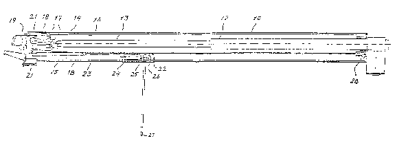
An embodiment of tha invention will be described in the follow-
ing ~tith ref~rence to the enclosed drawing. The drawing is a
sideview, partly in section, showing the hoisting device, which
can be attached ~lo~e to the ceiling of a room.
-~ In ths drawing 10 designates a hollow beam, which can have a
square cros~ saction or a circular croas section and which i8
fastened in hori~ontal position to a ceiling (not shown) by
mqans of any kind of means of attachment ~not shown). The beam
may alternatively be supported by a stand.
A linearly operating electric motor 12 is attached to tha beam,
which motor includeE a pi~ton 1 being displaceable in ths
longitudinal direction of the beam, the free end of which is
faatened to a slide 14 bein~ displaceable in the beam 10. The
slide 14 moves in guide~ within tho beam in a way not mora
closely shown A guide 15 and a ~uide 16 are ~chematically
shown. The sliding on the guides can be mada easier by meana of
; ~7heel~ or ~liding bodies (not ~hown). The load on the guide~ i~
the vartical direction i8 however not affected by the weight
carried by the hoi~ting device.
:'
A fir~t guide roller 17 i8 carried in bearing~ by the slide 14,
and a hoi~ti~g band 1~ is pa~ed over ~aid guide roller 17. One
end of the hoisting band 18 is attached to the free end of tha
bea~ 10 by maans of an attachm~nt 19. The ba~d 18 runs from the
attachment 19 and o~er the first guide roller 17 and theraafter
out to the frae end of the beam over a fir~t pulley whesl ~1 and
back to a ~econd guids rollar 17 on the slide 14 and thereafter
out to a aecond pull~y wheel 21. The know~ tschniqu~ teache
~5 that the band 18 thsn should run from the la~t mentioned pulley

:
whesl 21 do~nwards and a harnes~ or a chair should be carried by
the free end of the band in order to farry an individual to
hoist ~aid individual.
According to the invention the hoisting from different positions
along the beam 10 i8 made possible by that a trolley 22 i~
moveable along the beam. The trolley 22 rides with wheels 24 on
guides 23. The guides 23 may either be a part of the bottom of
the beam 10 or may be rails placed underneath tho beam 10. In
caYe the guites form a part of the hollow beam 10 a Blot i8
formed between tha guide~ 23 in the under~ide of the oeam. The
band 18 i~ pas~ed through the ~lot out of the be~m 10 and down-
wards in ord~r to carry a hook or any attachment under the beam.
The trolley 22 has two guided pulley6 25 and 26. The band la
thu~ run~ from the second pulley wheel 21 to the first guided
pulley 25 and downwards throuyh said slot (not shown) in the
beam 10 and forms a loop 27 under the beam. Therefrom the band
runs upwards and around the seaond guided pulley-26 and further
to the right in the plane of th~ drawing and is fixed at the
inner or the right end of the beam hy means of an attachment 28.
,
When the slide 14 i~ moved backwards and forwards 'oy the piston
13 the loup 27 will mo~e upward~ and downwards re~pectively in
relation to the beam 10. According to the ~howm e~bodi~ent tha
loop 27 will be elovatQd in r~lation to tha bea~ 10 wh~n the
slide 14 i~ moved in the direction toward~ tho motor 1~ and thus
an hoi~ting is per~ormed. The loop ~7 i~ low~red wh~n the slide
14 i~ moved in tha opposite direcion. The advantaye of the
invention is al~o that when the slide 14 i~ in a f~teady po~ition
the loop 27 can ~e displaced in a direction which is parallsl to
the beam 10. This is performed by that the trolley 22 iq moved
alony itB guides 23. When the slide 14 i~ in it~ steady position
th~ vertic=l po~ition of the loop 14 ~ill not be chang~d b~t
,''~ .

2 ~ 2 ~
, 4
only th~ position in hori~ontal direction. However it is alRo
obvious that the trolley can b~ di~placed along it~ guideP
simultaneously with a displacement of the Plide 14. The vertical
load i8 carried by the trolley 22 and the ~lide 14 i8 mainly
affected by horisontal forces from tha band 18.
According to the ~hown embodiment there ars two guide rollers 17
and two pulley wheels 21. Within the scops of the claims the
exten~ion of the band can be simplifiad by that only one guide
roller 17 and one pulley wheel 21 are ussd. Further there i8
shown an attachment 19 for one end of the band which is known
per 89. This attachment can includa a msans in which ths band i~
- reeled and whan ths hoisting device normally is operating thi~
'~ means for un~^7inding the band i~ locked BO th&t the band is fixed
in relation to the attachment. If however by some rea~on the
', electric motor 12 is not oparable, e.d. becausa of lack of
energy, the hoisting mean~ can opsrate in ons direction meaning
that the loop can be 10~7ersd by that tha lockiny action i8
released wh~reby thQ band can be unreeled ~o that the band i~
2~ elongated. Said fa~tening maans can be ~aid to be ~ome kind of a
winch with a reeled,lenght of the band having a relea~able
loc~ing devica which under normal operation prevents the band to
be unrseled from tha winch.

Dessin représentatif
Une figure unique qui représente un dessin illustrant l'invention.
États administratifs

2024-08-01 : Dans le cadre de la transition vers les Brevets de nouvelle génération (BNG), la base de données sur les brevets canadiens (BDBC) contient désormais un Historique d'événement plus détaillé, qui reproduit le Journal des événements de notre nouvelle solution interne.

Veuillez noter que les événements débutant par « Inactive : » se réfèrent à des événements qui ne sont plus utilisés dans notre nouvelle solution interne.

Pour une meilleure compréhension de l'état de la demande ou brevet qui figure sur cette page, la rubrique Mise en garde , et les descriptions de Brevet , Historique d'événement , Taxes périodiques et Historique des paiements devraient être consultées.

Historique d'événement

Description Date
Inactive : CIB de MCD 2006-03-11
Demande non rétablie avant l'échéance 1999-04-19
Le délai pour l'annulation est expiré 1999-04-19
Inactive : Abandon.-RE+surtaxe impayées-Corr envoyée 1998-04-17
Réputée abandonnée - omission de répondre à un avis sur les taxes pour le maintien en état 1998-04-17
Inactive : Demande ad hoc documentée 1997-04-17
Réputée abandonnée - omission de répondre à un avis sur les taxes pour le maintien en état 1997-04-17
Demande publiée (accessible au public) 1991-12-07

Historique d'abandonnement

Date d'abandonnement Raison Date de rétablissement
1998-04-17
1997-04-17
Titulaires au dossier

Les titulaires actuels et antérieures au dossier sont affichés en ordre alphabétique.

Titulaires actuels au dossier
GUNNAR LILJEDAHL
Titulaires antérieures au dossier
S.O.
Les propriétaires antérieurs qui ne figurent pas dans la liste des « Propriétaires au dossier » apparaîtront dans d'autres documents au dossier.
Documents

Pour visionner les fichiers sélectionnés, entrer le code reCAPTCHA :


Pour visualiser une image, cliquer sur un lien dans la colonne description du document. Pour télécharger l'image (les images), cliquer l'une ou plusieurs cases à cocher dans la première colonne et ensuite cliquer sur le bouton "Télécharger sélection en format PDF (archive Zip)" ou le bouton "Télécharger sélection (en un fichier PDF fusionné)".

Liste des documents de brevet publiés et non publiés sur la BDBC .

Si vous avez des difficultés à accéder au contenu, veuillez communiquer avec le Centre de services à la clientèle au 1-866-997-1936, ou envoyer un courriel au Centre de service à la clientèle de l'OPIC.


Description du
Document 
Date
(aaaa-mm-jj) 
Nombre de pages   Taille de l'image (Ko) 
Description 1991-12-07 4 150
Abrégé 1991-12-07 1 21
Dessins 1991-12-07 1 15
Page couverture 1991-12-07 1 13
Revendications 1991-12-07 2 46
Dessin représentatif 1998-07-20 1 9
Rappel - requête d'examen 1997-12-18 1 117
Courtoisie - Lettre d'abandon (taxe de maintien en état) 1998-05-19 1 186
Courtoisie - Lettre d'abandon (requête d'examen) 1998-06-01 1 171
Taxes 1997-04-04 1 48
Taxes 1996-04-11 1 40
Taxes 1995-04-05 1 39
Taxes 1994-04-12 1 34
Taxes 1993-04-19 1 29