Sélection de la langue

Search

Sommaire du brevet 2041090 

Énoncé de désistement de responsabilité concernant l'information provenant de tiers

Une partie des informations de ce site Web a été fournie par des sources externes. Le gouvernement du Canada n'assume aucune responsabilité concernant la précision, l'actualité ou la fiabilité des informations fournies par les sources externes. Les utilisateurs qui désirent employer cette information devraient consulter directement la source des informations. Le contenu fourni par les sources externes n'est pas assujetti aux exigences sur les langues officielles, la protection des renseignements personnels et l'accessibilité.

Disponibilité de l'Abrégé et des Revendications

L'apparition de différences dans le texte et l'image des Revendications et de l'Abrégé dépend du moment auquel le document est publié. Les textes des Revendications et de l'Abrégé sont affichés :

  • lorsque la demande peut être examinée par le public;
  • lorsque le brevet est émis (délivrance).
(12) Brevet: (11) CA 2041090
(54) Titre français: BANDES ALLONGEES POUR EMBOUTS D'ARRET DE FERMETURE A GLISSIERE
(54) Titre anglais: ELONGATED STRIPS FOR SLIDE FASTENER END STOPS
Statut: Périmé et au-delà du délai pour l’annulation
Données bibliographiques
(51) Classification internationale des brevets (CIB):
  • B21F 45/18 (2006.01)
  • A44B 19/24 (2006.01)
  • A44B 19/38 (2006.01)
(72) Inventeurs :
  • HIROTA, MINORU (Japon)
  • KUSE, KAZUKI (Japon)
  • KEYAKI, KEIICHI (Japon)
(73) Titulaires :
  • YKK CORPORATION
(71) Demandeurs :
  • YKK CORPORATION (Japon)
(74) Agent: GOWLING WLG (CANADA) LLP
(74) Co-agent:
(45) Délivré: 1994-03-29
(22) Date de dépôt: 1991-04-24
(41) Mise à la disponibilité du public: 1991-10-28
Requête d'examen: 1991-04-24
Licence disponible: S.O.
Cédé au domaine public: S.O.
(25) Langue des documents déposés: Anglais

Traité de coopération en matière de brevets (PCT): Non

(30) Données de priorité de la demande:
Numéro de la demande Pays / territoire Date
2-110099 (Japon) 1990-04-27

Abrégés

Abrégé anglais


ABSTRACT OF THE DISCLOSURE
An elongated strip providing a multiplicity of
prospective end stops for a slide fastener is disclosed. A
succession of prospective end stops in the strip are
interconnected by a flexible connecting cord such that the
strip can be disposed flexible and supple and thus
conveniently wound on a reel. Each end stop is reduced
centrally in thickness to provide a thin bridge which serves
as a hinge about which the end stop is accurately and easily
folded.

Revendications

Note : Les revendications sont présentées dans la langue officielle dans laquelle elles ont été soumises.


What is claimed is:
1. An elongated strip formed from a synthetic plastic
material and providing a multiplicity of prospective end
stop members for a slide fastener, said strip comprising a
succession of serially interconnected end stop members and a
plurality of flexible connecting means extending
longitudinally through opposite outer edges of said strip
and interconnecting adjacent ones of said end stop members
in spaced apart relation.
2. An elongated strip according to claim 1 wherein
each of said end stop members has a pair of identical legs
and a bridge of reduced thickness formed centrally between
said legs and serving as a hinge about which said legs are
folded across the width of said strip.
3. An elongated strip according to claim 2 wherein
said legs have respective peripheral edges rounded off and
protruding beyond the region of said bridge when said legs
are folded.
4. An elongated strip according to claim 1 wherein
said flexible connecting means is a textile yarn thread.
5. An elongated strip according to claim 1 wherein
said flexible connecting means is a synthetic plastic
monofilament.
6. An elongated strip according to claim 1 wherein
said flexible connecting means comprises an integral
extension of said strip which is reduced in thickness.
7. An elongated strip according to claim 2 wherein
- 7 -

each of said end stop members is notched from opposite ends
along a central longitudinal line of said strip to provide a
pair of oblong hights confronting each other across said
bridge.
- 8 -

Description

Note : Les descriptions sont présentées dans la langue officielle dans laquelle elles ont été soumises.

2~4~09~
BI~CKGROUND OF THE INVENTION
Field of the Invention
This invention relates to end stop members f~r slide
fasteners and more particularly to an elongated strip of a
synthetic resin having a multiplicity of serially
interconnected prospective end stop members.
Prior Art
End stop members made of a plastic, most commonly
thermoplastic material are usually preformed and applied
directly by injection molding onto a slide fastener tape at
one end thereof to form a top end stop or at the opposite
end to form a bottom end stop, such end stops being adapted
to limit the movement of a slider thereat to prevent the
latter from moving apart from the slide fastener. Injection
molding machines used in forming and applying slide fastener
end stops are rather difficult to handle with respect to
their thermal control and setting the end stops in
respective molds, particularly where end stops are switched
from one color to another entailing undue waste of time and
materials.
SUMMARY OF THE INVENTION
With the foregoing drawbacks of the prior art in view,
the present invention seeks to provide an elongated strip oE
a synthetic resin having a succession of interconnected end
stops which can be readily cut into an individual end stop
and subsequently firmly applied to a slide fastener
stringer.

2~34~L~90
The invention also seeks to provide such elongated
strips of various colors having a multiplicity of
prospective end stops flexibly interconnected such that each
strip ~an be stored conveniently separatedly in a reel or
other cartridge means.
The above and other advantages and features o~ the
invention will be better understood from the following
detailed description taken in conjunction with the
accompanying drawings which illustrate by way of example
some preferred embodiments.
sRIEF DESCRIPTION OF THE DRAWINGS
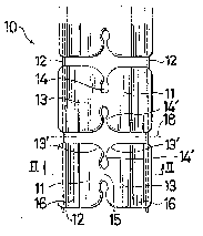
FIG. 1 is a fragmentary plan view on enlarged scale of
an elongated strip according to one form of the invention;
FIG. 2 is a transverse cross-sectional view taken on
the line II - II of FIG. l;
FIG. 3 is a transverse cross-sectional view o an
individual and stop showing the same folded for attachment
onto a slide fastener tape;
FIG. 4 is a cross-sectional view of the end stop shown
attached to the tape;
FIG. 5 is a fragmentary perspective view on enlarged
scale of a slide fastener stringer to which the end stop
from the strip is attached;
FIG. 6 is a perspective view of the strip shown wound
on a reel;
FIG. 7 is a view similar to FLG. 1 but showing a strip
according to another form of the invention;

o
FIG. 8 iS a fragmentary tranSverse cros~-sectional
view taken on the line VIII - VIII of FIG. 7;
FIG. 9 is a fragmentary perspective view on enlarged
scale of a strip according to still another form of the
invention; and
FIG. 10 is a fragmentary perspective view on enlarged
scale of a pair of slide fastener stringers to which the end
stop of FIG. 9 is attached.
DETAILED DESCRIPTION OF THE INVENTION
Referring now to the drawings and FIG. 1 in
particular, there is shown a portion of an elongated strip
10 formed from a synthetic plastic material and having a
succession of serially interconnected prospective end stop
members 11. Adjacent end stop members 11 are spaced apart
by a small distance and interconnected by a pair of flexible
connecting cords 12 such as of a textile yarn thread, a
synthetic plastic monoEilamënt or other flexible or pliable
materials, the cords 12 extending in parallel longitudinally
through opposite outer edges of the strip 10. Each of the
prospective end stop members 11 has a pair of identical legs
13, 13 which are adapted to fold across the width of the
strip 10 in a manner hereinafter described. Each end stop
member 11 is notched from opposite ends along a central
longitudinal line of the strip 10 to provide a pair of
inwardly expanded oblong bights 14 confronting each other
across a bridge 15 formed centrally between the legs 13, 13.
The edges 14' of each bight 14 merge with rounded-off inner
, ~ `.. ~''-', ' "': ' '
" ~' , .

2V~ O
peripheral edges 13', 13' of the respective legs 13, 13.
The bridge 15 is reduced in thickness as better shown in
FIG. 2 to serve as a hinge about which the end stop member
11 can be accurately and easily folded to bring the two legs
13, 13 in superimposed relation for mounting astride of a
tape edge as depicted in FIG. 3, in which instance the
rounded peripheral edges 13', 13' of the legs 13, 13
protrude outwardly beyond the bridge 15 as shown in FIG. 5.
As better shown in FIG. 2, the legs 13, 13 of the end
stop member ll each have an arcuate groove 16 extending
adjacently along their respective outer longitudinal edges
and configured to fit snugly over a beaded edge 17 of a
slide fastener stringer tape T which is usually cross-
sectionally round,
The elongated end stop forming strip lO thus
constructed is cut transversely along a line 18 extending
transversely across the connecting cords 12 between adjacent
prospective end stop members 11 to provide an individual end
stop 11'. This end stop 11' is shown attached with heat and
pressure as by means of the arrangement of a supersonic horn
l9 and an anvil 20 schematically shown in FIG. 4 onto a top
end portion of a slide fastener stringer F which as shown in
FIG. 5 comprises a support tape T and a row of coupling
elements E secured thereto. Advantageously, the end stop
11' when thus attached to the support tape T is free of any
sharp edge portions which tend to catch and impair a garment
fabric on which the slide fastener is used. This is due to

the ConStruction of the end stop 11' in which the bridge 15
about which it is folded is protected by the rounded-off
peripheral edges 13', 13l of the legs 13, 13 which protrude
beyond the region of the bridge 15 as better shown in FIG.
5.
Further advantageously, the prospective end stop
members 11 are interconnected by the flexible connecting
cords 12 which render the strip 10 flexible and supple as a
whole, thus allowing a substantial length of the strip 10
to be conveniently wound on a reel 30 as depicted in FIG. 6.
A modified elongated strip lOa according to the
invention is shown in FIGS. 7 and 8 and is substantially
geometrically identical to the strip 10 in FIG. 1 in that
each of the prospective end stop members lla comprises a
pair of identical legs 13a, 13a, a pair of hights 14a, 14a,
a bridge 15a and a groove 16a, except that the succession of
prospective end stop members lla are interconnected by a
connecting extension 21 integral with adjacent end stop
members lla in lieu of the use of the flexible connecting
cords 12. The connecting extension 21 extends between
adjacent end stop members lla and is reduced in thickness as
shown in FIG~ 8 so as to be easily cut along a transverse
cut line 18a.
FIG. 9 shows a further modified form of strip lOb
according to the invention which is adapted to be applied to
a bottom end portion of slide fastener stringers F as shown
in FIG. 10. The strip lOb has a multiplicity of
, ~

Z04~L~39(~
interconnected prospective end stop members llb each of
which comprises a stem 22 and a pair of upper and lower legs
13b extending laterally from opposite sides of the stem 22
and defining therebetween an arcuate groove 16b for
receiving and clamping the beaded edge 17 of the stringer
tape T as shown in FIG. 10. Importantly, adjacent end stop
members llb are interconnected by flexible connecting cords
12b which are similar to those used in the embodiment o~
FIGS. 1 - 5 and which extend longitudinally through opposite
outer edges of the strip lOb, the arrangement being that the
structure of the strip 10b is rendered flexible and supple as
a whole to permit a substantial length of the strip lOb to .
be reeled for convenient storage.
Obviously, various modifications and variations of the
present invention are possible in the light of the above
teaching. It is therefore to be understood that within the
scope of the appended claims the invention may be practiced
otherwise than as specifically described.

Dessin représentatif
Une figure unique qui représente un dessin illustrant l'invention.
États administratifs

2024-08-01 : Dans le cadre de la transition vers les Brevets de nouvelle génération (BNG), la base de données sur les brevets canadiens (BDBC) contient désormais un Historique d'événement plus détaillé, qui reproduit le Journal des événements de notre nouvelle solution interne.

Veuillez noter que les événements débutant par « Inactive : » se réfèrent à des événements qui ne sont plus utilisés dans notre nouvelle solution interne.

Pour une meilleure compréhension de l'état de la demande ou brevet qui figure sur cette page, la rubrique Mise en garde , et les descriptions de Brevet , Historique d'événement , Taxes périodiques et Historique des paiements devraient être consultées.

Historique d'événement

Description Date
Le délai pour l'annulation est expiré 2007-04-24
Lettre envoyée 2006-04-24
Inactive : CIB de MCD 2006-03-11
Accordé par délivrance 1994-03-29
Demande publiée (accessible au public) 1991-10-28
Toutes les exigences pour l'examen - jugée conforme 1991-04-24
Exigences pour une requête d'examen - jugée conforme 1991-04-24

Historique d'abandonnement

Il n'y a pas d'historique d'abandonnement

Historique des taxes

Type de taxes Anniversaire Échéance Date payée
TM (brevet, 7e anniv.) - générale 1998-04-24 1998-02-20
TM (brevet, 8e anniv.) - générale 1999-04-26 1999-01-12
TM (brevet, 9e anniv.) - générale 2000-04-24 2000-02-01
TM (brevet, 10e anniv.) - générale 2001-04-24 2001-01-05
TM (brevet, 11e anniv.) - générale 2002-04-24 2002-03-18
TM (brevet, 12e anniv.) - générale 2003-04-24 2003-03-17
TM (brevet, 13e anniv.) - générale 2004-04-26 2004-03-17
TM (brevet, 14e anniv.) - générale 2005-04-25 2005-03-07
Titulaires au dossier

Les titulaires actuels et antérieures au dossier sont affichés en ordre alphabétique.

Titulaires actuels au dossier
YKK CORPORATION
Titulaires antérieures au dossier
KAZUKI KUSE
KEIICHI KEYAKI
MINORU HIROTA
Les propriétaires antérieurs qui ne figurent pas dans la liste des « Propriétaires au dossier » apparaîtront dans d'autres documents au dossier.
Documents

Pour visionner les fichiers sélectionnés, entrer le code reCAPTCHA :


Pour visualiser une image, cliquer sur un lien dans la colonne description du document (Temporairement non-disponible). Pour télécharger l'image (les images), cliquer l'une ou plusieurs cases à cocher dans la première colonne et ensuite cliquer sur le bouton "Télécharger sélection en format PDF (archive Zip)" ou le bouton "Télécharger sélection (en un fichier PDF fusionné)".

Liste des documents de brevet publiés et non publiés sur la BDBC .

Si vous avez des difficultés à accéder au contenu, veuillez communiquer avec le Centre de services à la clientèle au 1-866-997-1936, ou envoyer un courriel au Centre de service à la clientèle de l'OPIC.

({010=Tous les documents, 020=Au moment du dépôt, 030=Au moment de la mise à la disponibilité du public, 040=À la délivrance, 050=Examen, 060=Correspondance reçue, 070=Divers, 080=Correspondance envoyée, 090=Paiement})


Description du
Document 
Date
(aaaa-mm-jj) 
Nombre de pages   Taille de l'image (Ko) 
Revendications 1994-07-08 2 36
Abrégé 1994-07-08 1 12
Dessins 1994-07-08 4 60
Description 1994-07-08 6 175
Dessin représentatif 1998-07-07 1 9
Avis concernant la taxe de maintien 2006-06-18 1 172
Taxes 1996-03-12 1 76
Taxes 1995-03-15 1 84
Taxes 1997-03-24 1 79
Taxes 1993-01-06 1 52
Taxes 1994-03-02 1 69
Correspondance reliée au PCT 1993-12-21 1 28
Courtoisie - Lettre du bureau 1991-11-19 1 36