Sélection de la langue

Search

Sommaire du brevet 2041182 

Énoncé de désistement de responsabilité concernant l'information provenant de tiers

Une partie des informations de ce site Web a été fournie par des sources externes. Le gouvernement du Canada n'assume aucune responsabilité concernant la précision, l'actualité ou la fiabilité des informations fournies par les sources externes. Les utilisateurs qui désirent employer cette information devraient consulter directement la source des informations. Le contenu fourni par les sources externes n'est pas assujetti aux exigences sur les langues officielles, la protection des renseignements personnels et l'accessibilité.

Disponibilité de l'Abrégé et des Revendications

L'apparition de différences dans le texte et l'image des Revendications et de l'Abrégé dépend du moment auquel le document est publié. Les textes des Revendications et de l'Abrégé sont affichés :

  • lorsque la demande peut être examinée par le public;
  • lorsque le brevet est émis (délivrance).
(12) Brevet: (11) CA 2041182
(54) Titre français: ACCOUPLEMENT HYDRAULIQUE
(54) Titre anglais: HYDRAULIC COUPLING
Statut: Périmé et au-delà du délai pour l’annulation
Données bibliographiques
(51) Classification internationale des brevets (CIB):
  • F16L 19/08 (2006.01)
  • F16L 19/02 (2006.01)
  • F16L 19/025 (2006.01)
(72) Inventeurs :
  • WILLIAMSON, NIGEL D. L. (Etats-Unis d'Amérique)
(73) Titulaires :
  • NWD INTERNATIONAL, INC.
(71) Demandeurs :
  • NWD INTERNATIONAL, INC. (Etats-Unis d'Amérique)
(74) Agent: SMART & BIGGAR LP
(74) Co-agent:
(45) Délivré: 1994-08-30
(22) Date de dépôt: 1991-04-25
(41) Mise à la disponibilité du public: 1991-11-09
Requête d'examen: 1991-04-25
Licence disponible: S.O.
Cédé au domaine public: S.O.
(25) Langue des documents déposés: Anglais

Traité de coopération en matière de brevets (PCT): Non

(30) Données de priorité de la demande:
Numéro de la demande Pays / territoire Date
07/520,216 (Etats-Unis d'Amérique) 1990-05-08

Abrégés

Abrégé anglais


The invention is an improved hydraulic
coupling wherein the male and female fittings
include complementary tapered surfaces and the
male fitting is axially urged into engagement with
the female fitting by means of a threaded nut.
The male fitting is provided with a shoulder
behind its tapered surface and abuts a surface on
the female member to thereby limit the axial
movement of the male member and prevent nose
collapse.

Revendications

Note : Les revendications sont présentées dans la langue officielle dans laquelle elles ont été soumises.


THE EMBODIMENTS OF THE INVENTION IN WHICH AN EXCLUSIVE PROPERTY
OR PRIVILEGE IS CLAIMED ARE DEFINED AS FOLLOWS:
1. A hydraulic coupling, comprising:
a female fitting member having a central bore having a
central axis, an internal tapered locking surface and external
threads parallel to the axis;
a male fitting member being received within said female
member and having a central bore coaxial with the bore of said
female member, an external tapered locking surface complementary
to said female tapered surface, an annular groove in said male
tapered locking surface and an O-ring of deformable material in
said groove, said O-ring having a cross-sectional height which
is greater than the minimum depth of said groove and extends
above said groove, said male fitting member further having a
flange portion located immediately behind said external tapered
surface and having a diameter greater than the outer diameter of
said external tapered surface to define a stop shoulder facing
an abutment surface of said female fitting member, said male
member further comprising a second shoulder located behind said
stop shoulder and facing in a direction opposite to said stop
shoulder, said tapered locking surfaces being smooth; and
a nut member having threads that are parallel to the axis
and to the threads of said female member and are connected to the
threads of said female member, said nut member provided with
abutment means for abutting said second shoulder of said male
member to thereby force said tapered surfaces together and deform
said O-ring;
said stop shoulder being in abutment with said female member
abutment surface to thereby limit the travel of said male member
within said female member and prevent collapse of said male

member in the area of its external tapered surface, said male and
female members and said nut member being dimensioned such that
said tapered locking surfaces abut each other at about the same
time as said stop shoulder and female member abutment surface
abut each other as said coupling is assembled, there being
substantially no further relative movement between said male and
female fitting members after abutment of said nut and said second
shoulder and abutment of said stop shoulder and said female
member abutment surface.
2. The coupling of claim 1 wherein said abutment means on said
nut member includes a shoulder in engagement with said second
shoulder of said male member.
3. The coupling of claim 2 wherein said tapered surfaces are
tapered at an angle of about 12 degrees relative to the axis of
said bores.
4. The coupling of claim 1 wherein said tapered surfaces are
tapered at an angle of about 12 degrees relative to the axis of
said bores.
5. The coupling of claim 1 wherein said tapered surfaces are
tapered at an angle of about 30 degrees relative to the axis of
said bores.
6. The coupling of claim 1 wherein said tapered surfaces and
said second shoulder are dimensioned such that, during assembly
of said members, said second shoulder and said abutment surface

on said female member are separated by a slight gap when said
tapered surfaces just form an interference fit with each other
without the application of torque.
7. The coupling of claim 6 wherein said gap is between about
0.005 inches to about 0.100 inches.

Description

Note : Les descriptions sont présentées dans la langue officielle dans laquelle elles ont été soumises.


2041182 -
The present invention relates to a hydraulic
coupling for interconnecting hydraulic hoses or
connecting hoses to various hydraulic fittings,
such as adapters and the like.
A commonly used fitting, particularly in
European countries, comprises a body having a
threaded portion with a bore and an internal
tapered seat. A fitting, which is adapted to be
connected to a pipe or tubing, for example, is
provided with a forwardly facing tapered external
surface having a groove therein and an 0-ring
disposed within the groove. The fitting also
includes a rearwardly facing shoulder which is
engaged by a shoulder on a nut that encloses the
fitting and is threadedly connected to the
threaded portion of the body. As the nut is
tightened on the threaded portion of the body, the
fitting is advanced forwardly against the internal
tapered seat and the 0-ring is compressed to
thereby form a fluid-tight seal.
A problem with this type of prior art fitting
involves "nose collapse", which occurs when the
externally tapered male fitting is driven down,
under heavy torque, inside the tapered internal
seat. The collapse of the nose of the male
fitting is directly related to the amount of the
linear travel of the fitting once engaged with the
female tapered surface as a trigonometric function
of the angle of the taper. In such European style
fittings, the taper is typically 12 relative to
the axis, although there is also a 30
configuration.
If the installer tightens the fitting beyond
the point where the tapered surfaces meet and the
0-ring is compressed, the annular portion of the

2~411 8~
,
male fitting in the area of the groove and O-ring
will be collapsed inwardly, thereby damaging the
fitting and thereby restricting the flow of the
fluid medium.
The present invention constitutes an
improvement to the aforementioned European type
fitting wherein the problem of nose collapse is
eliminated. The male fitting member is provided
with a shoulder located behind the external
tapered surface, which shoulder functions as a
stop surface and abuts an abutment surface on the
body portion of the coupling body that is in axial
alignment with the shoulder. The shoulder is
located dimensionally relative to the external
tapered surface such that the shoulder will abut
the leading edge of the coupling body just beyond
the point where the tapered surfaces contact each
other. Thus, the axial movement of the male
fitting will be terminated at this point so that
collapse of the nose portion thereof is avoided.
The present invention, in one form thereof,
is a hydraulic coupling that comprises a female
fitting having a central bore, an internal tapered
surface and external threads. A male fitting is
received within the female member and has a
central bore coaxial with the bore of the female
member, an external tapered surface complementary
to the female tapered surface and an annular
groove in the male tapered locking surface. An 0-
ring of deformable material is disposed in the
groove. The male fitting member includes a flange
portion located immediately behind the external
tapered surface having a diameter greater than the
outer diameter of the external tapered surface to
define a stop shoulder facing the abutment surface
of the female fitting. The male member may

204~L18~
further comprise a second shoulder located behind
the stop shoulder and facing in an opposite
direction. A nut member is threadedly connected
to the female member and engages the rearwardly
facing shoulder of the male member to thereby
force the tapered surfaces together and deform the
O-ring. The stop shoulder is in abutment with the
female member abutment surface to thereby limit
the travel of the male member within the female
member and prevent collapse of the nose portion of
the male member.
An advantage of the present invention is that
the nose portion of the male fitting is protected
against nose collapse without the necessity for
modifying the standard nut and female component of
the coupling.
The above mentioned and other features and
advantages of the invention will become more
apparent and the invention itself will be better
understood by reference to the following
description of an embodiment of the invention
taken in conjunction with the accompanying
drawings, wherein:
Fig. 1 is an exploded, sectional view of the
hydraulic coupling according to the present
invention; and
Fig. 2 is a sectional view of the assembled
coupling.
Corresponding reference characters indicate
corresponding parts throughout the views. The
exemplification set out herein illustrate a
preferred embodiment of the invention and such
exemplifications are not to be construed as
limiting the scope of the disclosure or the scope
of the invention in any manner.

2~118~
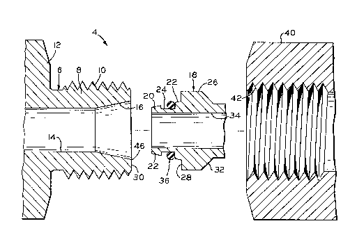
The coupling 4 according to the present
invention comprises a standard female member 6
having a threaded portion 8 with external threads
10 thereon and a flange portion 12. Threaded
portion 8 and flange portion 12 include an
internal bore 14 and an internally tapered seat 16
in communication with bore 14. Female member 6 is
a standard body utilized in the aforementioned
European-type coupling.
Male fitting 18 includes a tapered nose
portion 20 having an externally tapered surface 22
with an annular groove 24 therein located
approximately midway of the tapered surface 22.
Surface 22 may be tapered at an angle of 12
relative to the axis, which is the identical taper
of internal seat 16 and female member 6. A flange
portion 26 is disposed immediately behind tapered
surface 22 and defines a forwardly facing shoulder
28, which is in axial alignment with the leading
edge 30 of female member 6. Flange portion 28
further defines a rearwardly facing shoulder 32,
which may be tapered as shown in the figures.
Male fitting member includes an internal bore 34
in fluid communication with bore 14 when the
coupling 4 is assembled. An o-ring 36 is disposed
within groove 24 and extends above tapered surface
22. O-ring 36 may be formed of any suitable
elastomeric or resilient rubber-like material
conventionally used for making deformable O-rings
used in hydraulic fittings.
Standard nut 40 includes internal threads 42
that are adapted to be threadedly engaged with
external threads 10 of female member 6. Nut 40 is
preferably formed with hexagonal flats on the
exterior surface so that it can be tightened onto

2Q4 1i82
-
female member 6 by means of a wrench or other
suitable tool.
Fig. 2 illustrates the manner in which the
elements constituting hydraulic coupling 4 are
assembled. Male fitting member 18, which is
adapted to be connected to a tube or pipe, is
initially received within nut 40 and nut 40 is
then threaded onto the externally threaded portion
8 of female member 6. As nut 40 is turned,
10 shoulder 44 thereon engages shoulder 32 of male
member 18 and urges it forwardly toward female
member 6 whereupon tapered surface 16 deforms 0-
ring 36 to form a liquid-tight seal between male
fitting 18 and female fitting 6. As nut 40
15 continues to be advanced, eventually tapered
surfaces 22 and 16 move into radial abutment. If
stop shoulder 28 were not provided, as is the case
with prior art couplings of this type, continued
advancement of nut 40 would drive tapered nose
20 portion 20 further into the bore defined by
internal tapered surface 16, thereby possibly
causing collapse of the nose portion 20 of male
member 18. However, in accordance with the
present invention, stop shoulder 28 will abut
25 surface 30 on female member 6 before this can
occur, thereby limiting the extent of axial travel
of male member 18 and permitting nut 40 to be
tightened on female member 6 without damage to
male fitting 18.
However, to ensure that there is a tight seal
and a certain amount of frictional locking between
tapered surfaces 16 and 22, stop shoulder 28 is
dimensioned so that there is a slight gap between
it and leading edge 30 at the time that an
35 interference fit between surfaces 16 and 22 occurs
without the application of any torque, that is,

2 0 ~
when the breakout diameter 46 of female member 6
just contacts tapered surface 22 on male fitting
18. This gap is preferably in the range of .005
inches (.127 mm) to 0.100 inches (2.54 mm).
Further advancement of male member 18 to close
this gap until surfaces 28 and 30 abut will cause
the proper amount of frictional engagement between
tapered surfaces 16 and 22. No further movement
is possible even when excess torque is applied
because the abutting surfaces will limit further
travel. Furthermore, an assembler of the fitting
will be able to sense by feel when the fittings
are properly assembled.
The improvement of the present invention can
be applied to all couplings of the type disclosed,
such as the 12 taper described above as well as
the 30 taper fittings, which are also in common
use.
While this invention has been described as
having a preferred design, the present invention
can be further modified within the spirit and
scope of this disclosure. This application is
therefore intended to cover any variations, uses,
or adaptations of the invention using its general
principles. Further, this application is intended
to cover such departures from the present
disclosure as come within known or customary
practice in the art to which this invention
pertains and which fall within the limits of the
3 0 appended claims .

Dessin représentatif
Une figure unique qui représente un dessin illustrant l'invention.
États administratifs

2024-08-01 : Dans le cadre de la transition vers les Brevets de nouvelle génération (BNG), la base de données sur les brevets canadiens (BDBC) contient désormais un Historique d'événement plus détaillé, qui reproduit le Journal des événements de notre nouvelle solution interne.

Veuillez noter que les événements débutant par « Inactive : » se réfèrent à des événements qui ne sont plus utilisés dans notre nouvelle solution interne.

Pour une meilleure compréhension de l'état de la demande ou brevet qui figure sur cette page, la rubrique Mise en garde , et les descriptions de Brevet , Historique d'événement , Taxes périodiques et Historique des paiements devraient être consultées.

Historique d'événement

Description Date
Le délai pour l'annulation est expiré 2010-04-26
Lettre envoyée 2009-04-27
Inactive : Lettre officielle 2007-03-06
Inactive : Paiement correctif - art.78.6 Loi 2007-01-30
Inactive : CIB de MCD 2006-03-11
Inactive : Demande ad hoc documentée 1998-04-25
Lettre envoyée 1997-04-25
Accordé par délivrance 1994-08-30
Demande publiée (accessible au public) 1991-11-09
Toutes les exigences pour l'examen - jugée conforme 1991-04-25
Exigences pour une requête d'examen - jugée conforme 1991-04-25

Historique d'abandonnement

Il n'y a pas d'historique d'abandonnement

Historique des taxes

Type de taxes Anniversaire Échéance Date payée
TM (brevet, 7e anniv.) - générale 1998-04-27 1998-03-20
TM (brevet, 8e anniv.) - générale 1999-04-26 1999-04-26
TM (brevet, 9e anniv.) - générale 2000-04-25 2000-03-20
TM (brevet, 10e anniv.) - générale 2001-04-25 2001-03-16
TM (brevet, 11e anniv.) - générale 2002-04-25 2002-03-25
TM (brevet, 12e anniv.) - générale 2003-04-25 2003-03-24
TM (brevet, 13e anniv.) - générale 2004-04-26 2004-03-31
TM (brevet, 14e anniv.) - générale 2005-04-25 2005-04-06
TM (brevet, 15e anniv.) - générale 2006-04-25 2006-03-17
2007-01-30
TM (brevet, 16e anniv.) - générale 2007-04-25 2007-03-09
TM (brevet, 17e anniv.) - générale 2008-04-25 2008-04-03
Titulaires au dossier

Les titulaires actuels et antérieures au dossier sont affichés en ordre alphabétique.

Titulaires actuels au dossier
NWD INTERNATIONAL, INC.
Titulaires antérieures au dossier
NIGEL D. L. WILLIAMSON
Les propriétaires antérieurs qui ne figurent pas dans la liste des « Propriétaires au dossier » apparaîtront dans d'autres documents au dossier.
Documents

Pour visionner les fichiers sélectionnés, entrer le code reCAPTCHA :


Pour visualiser une image, cliquer sur un lien dans la colonne description du document (Temporairement non-disponible). Pour télécharger l'image (les images), cliquer l'une ou plusieurs cases à cocher dans la première colonne et ensuite cliquer sur le bouton "Télécharger sélection en format PDF (archive Zip)" ou le bouton "Télécharger sélection (en un fichier PDF fusionné)".

Liste des documents de brevet publiés et non publiés sur la BDBC .

Si vous avez des difficultés à accéder au contenu, veuillez communiquer avec le Centre de services à la clientèle au 1-866-997-1936, ou envoyer un courriel au Centre de service à la clientèle de l'OPIC.

({010=Tous les documents, 020=Au moment du dépôt, 030=Au moment de la mise à la disponibilité du public, 040=À la délivrance, 050=Examen, 060=Correspondance reçue, 070=Divers, 080=Correspondance envoyée, 090=Paiement})


Description du
Document 
Date
(aaaa-mm-jj) 
Nombre de pages   Taille de l'image (Ko) 
Abrégé 1993-11-19 1 13
Revendications 1993-11-19 3 119
Dessins 1993-11-19 1 36
Description 1993-11-19 6 244
Description 1994-08-29 6 249
Abrégé 1994-08-29 1 13
Revendications 1994-08-29 3 89
Dessins 1994-08-29 1 38
Dessin représentatif 1999-08-18 1 18
Avis concernant la taxe de maintien 2009-06-07 1 171
Correspondance 2007-03-05 1 12
Taxes 2008-04-02 1 40
Taxes 1997-04-03 1 47
Taxes 1996-04-23 1 40
Taxes 1995-04-24 1 45
Taxes 1994-04-21 1 47
Taxes 1993-04-15 1 32
Correspondance reliée au PCT 1994-06-06 1 39
Courtoisie - Lettre du bureau 1991-11-24 1 36
Demande de l'examinateur 1993-08-24 1 54
Correspondance de la poursuite 1994-01-23 1 33