Note : Les descriptions sont présentées dans la langue officielle dans laquelle elles ont été soumises.
302-331-6
BACKGROUNL) ART
For many years, safe, trouble-free delivery or
transferral of various liquids, particularly flammable
liquids and toxic or hazardous liquids, has long been a
problem which has plagued the industry. In particular, in
situations where small quantit.i.es of flammable or toxic
liquids are to be transferred from a storage container to
an active, useable reservoir, such as the gasoline tank of
motor vehicles or a holding tank for dilution, the
difficulties typically encountered with transferring
flammable liquids become most acute.
In an attempt to reduce or eliminate these difficulties,
various systems and adaptors have become available.
However, these prior art systems have failed to eliminate
the inherent danger or to overcome the problems and dangers.
The most severE problems being encountered are the
spontaneous eruption of an uncontrolled fire and unwanted
explosions often followed by fire. These catastrophic
incidents have occurred most frequently in the ~apzd
delivery of gasoline from a storage container to the tank
or reservoir of a vehicle during an on-going race>
2~~~~~~
2 - 302°331-6
In such situations, particularly with racing cars,
motorcycles and all terrain vehicles, speed of delivery is
important. Iri addition, particularly with motorcycles, all
terrain vehicles and small cars, the fuel tank size does
not allow pressurized pump deliver; systems. Consequently,
gravity delivery is employed, with the desirability of high
speed often leading to carelessness.
In these gravity-based delivery situations, it has been
found that gasoline vapors build up in the storage container
prior to use, particularly when the ambient temperatures
are high or the storage tanks are left out in direct sun-
light. nuring the rush to rapidly fill the gasoline tank
for continued racing, the storage tank is inadvertently
not vented prior to use. Consequently, the highly
flammable, pressurized gasoline vapors are allowed to come
into rapid contact with the hot motox vehicle, often
causing an unwanted fire or explosion.
In addition,,prior art delivery systems have failed to
eliminate unwanted spillage. Consequently, gasoline is
often spilled on the hot motor vehicle during the delivery
process. This spillage is also very dangerous and has also
resulted in unwanted fires.
- 3 - 302-331-6
Similarly, in transferring toxic or hazardous liquids,
spillage continues to be a primary problem, as well as
unsafe disposal of the container bearing the concentrated
toxic liquid after it is used.
Although these problems and difficulties have existed
in the industry for many years, no prior art system exists
which completely eliminates the inherent dangers found in
these liquid delivery situations.
Therefore, it is a principal object of the present
invention to provide a liquid flow controlling system which
is capable of controllably delivering liquid to a tank or
container in a safe, error free manner.
Another object of the present invention is to provide a
liquid flow controlling system having the characteristic
features described above which provides positive, automatic
flow control means to assure that the liquid is being
delivered only when safe to do so.
Another object of the present invention is to provide a
liquid flow controlling system having the characteristic
features described above which substantially reduces any
chance of fires or explosions during the gravity delivery
of liquid from one reservoir to another.
~D~~~p~
- 302-331-6
Another object of the present invention is to provide a
liquid flow controlling system having the characteristic
features described above which virtually eliminates
dangerous spillage of the liquid being delivered.
Other and more specific objects will in part be obvious
and will in part appear hereinafter.
- 302-331-6
SUNtMARY Of THE INVENTION
The present invention overcome: prior art difficulties
by providing two separate and distinct flow channels both
of which are controllably opened in a specific, pre-set
sequence, upon actuation. In this way, the liquid
delivery/filling system o.f the pre~oent invention assures
that upon actuation the liquid is safely delivered from the
first storage reservoir to the second active reservoir,
while being completely closed prior to actuation.
By providing two completely independent and separate
flow channels, the liquid is controllably delivered along
one flow path or channel, while the second flow path or
channel assures controlled removal of displaced air from
the chamber being filled. In addition, the air is delivered
to a zone above the liquid levele This prevents unwanted
air flow or bubbling through the liquid itself, thereby
eliminating one primary source of spillage.
Furthermore, by mounting the system in a normally
closed position and providing the sequential controlled
actuation of the two independent flow channels when
desired, the liquid delivery/filling system of the present
invention eliminates the second source of spillage, as well
~~~~~fl~
- 302-331-6
as safely controlling any vapor build up in the storage
container. The present invention substantially reduces any
possibility that vapor pressure build up will be
accidentally ignited or that liquid will be spilled in
unwanted or undesirable areas.
In the preferred construction, the two, independent
flow channels are constructed concentrically, in order to
provide a compact and easily useable construction. In
addition, the controlled, sequential actuation is achieved
in a positive, automatic error free manner. As a result,
regardless of user knowledge, trouble-free use is attained.
Furthermore, the liquid delivery/filling system of the
present invention incorporates flow shut-off means which
automatically discontinues the delivery of the liquid to
the active reservoir when the reservoir has been filled.
By incorporating automatic flow shut-off means, in
combination with the other features detailed above, 'the
fluid delivery/filling system of the present invention
provides for the safe transferral or delivery of flammable
or toxic liquids, without the dangers and problems that
have plagued the industry.
In addition, in order to provide for the safe
transferral of flammable or toxic liquids from a storage
- 302-331-6
container to an active, useable container or reservoir, the
present invention also comprises a cooperating, mating,
system-engaging refilling assembly for being lockingly
mounted to the liquid delivery/filling system, securing the
system in its open position and enabling the storage
container to be refilled both safely and speedily. In this
way, the storage container can be repeatedly reused after
the safe refilling thereof, thereby enabling 'the liquid
delivery/filling system mounted thereto to be continuously
used to prevent unwanted spillage.
The integrated, interlocking mating/refilling assembly
of this invention is of particular importance in assuring
the safe delivery and use of toxic and hazardous chemicals
and liquids, such as chemical fertilizers, pesticides and
insecticides which are environmentally safe when diluted,
but highly toxic or hazardous when spilled in their
concentrated form: In many applications throughout the
country, chemical fertilizers, pesticides and insecticides
are applied to crops, plants, trees, etc. in order to
either enhance their growth or reduce or eliminate the
damage caused by insects or other crop feeding animals.
Typically, the concentrated toxic or hazardous chemical
liquids are transferred from a liquid storage container to
- 302-331-6
an active, useable reservoir in which the toxic chemical
liquid is diluted far safe application to the crops,
plants, trees or other farmed product. In order to assure
safe, trouble-free transferral of the hazardous or toxic
concentrated chemical liquids from the storage container to
the active, useable reservoir, the liquid delivery/filling
system of the present invention is employed,
In this particular application, it has been found that
toxic or hazardous liquids have been able to cause unwanted
contamination due to the discarding of the storage
container used for holding the concentrated hazardous
chemical liquid. Consequently, in order to eliminate this
unwanted contamination, an alternate embodiment of the
present invention comprises an integrated, interlocking
mating/refilling assembly which cooperatingly engages the
liquid delivery/filling system for enabling the storage
container to be refilled. rn this way, the storage
container is repeatedly reused, thereby preventing its
disposal and the unwanted contamination of. the surrounding
environment by the residual chemicals contained therein.
In order to enable the storage container to be
repeatedly reused, the liquid delivery/filling system is
preferably fixedly mounted to the storage container and the
- ~ - 302-331-6
cooperating, integrated, interlocking mating/refilling
assembly lockingly mounts to the liquid delivery/filling
system, autamatically causing the dlelivery/filling system
to be fixed in its open position, enabling the safe,
efficient, spill-free refilling of the storage container
for subsequent reuse. In this way, the storage containers
are not discarded arid, thereby, do not cause
contamination. Furthermore, each concentrated chemical
holding storage container incorporates a liquid
delivery/filling system of this invention, thereby
effectively eliminating unwanted spillage of the toxin
liquid contained therein.
The invention accordingly comprises an article of
manufacture possessing the features, properties, and the
relation of elements which will be exemplified in the
article hereinafter described, and the scope of the
invention will be indicated in the claims.
" 10 - 302-331-6
THE DRAWINGS
For a fuller understanding of the nature and objects of
the invention, reference should be had to the following
detailed description taken in connection with the
accompanying drawings, in which:
FIGURE 1 is a side elevational view of the fluid
delivery/filling system of the present invention shown
fully assembled, and in its normally closed position;
FIGURE 2 is a cross-sectional side elevational view of
the liquid delivery and filling system of the present
invention taken along line 2-2 of FIGURE l:
FIGURE 3 is an exploded perspective view of the FLUID
delivery/filling system of the present invention;
FIGURE 4 is a side elevational view, partially in
cross-section and partially broken away, of the fluid
delivery and filling system of the present invention shown
in its partially open position;
FIGURE 5 is a side elevational view, partially in
cross-section and partially broken away, of the fluid
delivery/filling system of the present invention shown in
its fully open position;
- 11 - 302-331-6
FIGURE 6 is a diagrammatic view, partially in cross-
section and partially broken away showing the liquid
delivery/filling system of the present invention in use
transferring fluid from one reservoir into another;
FIGURE 7 is a side elevational view of the liquid
delivery/filling system of the present invention shown in '
operation as the tank being filled nears completion;
FIGURE 8 is a side elevational view showing the liquid
transfer assembly of the present invention;
FIGURE 9 is a top plan view of the liquid transfer
assembly of FIGURE 8;
FIGURE 10 is a side elevation view showing a slightly
modified embodiment of the liquid delivery/filling system
of this invention;
FIGURE 11 is a side elevation view, partially broken
away, depicting the liquid transfer assembly of the present
invention in locked engagement with the liquid delivery/
filling system of this invention, with the liquid delivery/
filling system securely mounted to a reuseable container;
FIGURE 12 is a side elevation view, partially broken
away, similar to the view of FIGURE 11, with the liquid
transfer assembly of the present invention depicted
securely affixed to the liquid delivery/filling system of
this invention;
~~~1~~~
- 12 - 302-331-6
FIGURE 13 is a schematic view depicting the closed
loop, fully controlled, spill free, gravity free, liquid
distribution system attained by employing the integrated,
cooperating, liquid flow controlling system of th.i.s
invention;
FIGURE 14 is a side elevation view of an alternate
preferred embodiment of the liquid transfer assembly of
this invention;
FIGURE 15 is a side elevation view, partially broken
away, depicting an alternate prefe:~red embodiment of the
liquid deliverylfilling assembly of the present invention
securely affixed to a container;
FIGURE 16 is a top plan view of the liquid transfer
assembly of FIGURE 14;
FIGURE 17 is an enlarged top plan view of the liquid
transfer assembly similar to FIGURE 16, but shown with the
cover plate removed and the activation switch in the off
position;
FIGURE 18 is a top plan view of the liquid transfer
assembly similar to FIGURE 17, depicting the activation
switch in the on position;
~f3~1 i~3~
- 1.3 - 302-331-6
FIGURE 19 is a cross-sectional side elevation view,
partially broken away, of the liquid transfer assembly
showing the interlock system taken along line 19-19 of
FIGURE 17;
FIGURE 20 is a cross-sectional side elevation view,
partially broken away, showing the interlock system of the
liquid transfer assembly taken along line 20-20 of
FTGURE 18;
FIGURE 21 is a cross-sectional side elevation view of
the liquid transfer assembly of the present invention taken
along line 21-21 of FIGURE 17;
FIGURE 22 is a cross-sectional side elevation view of
the liquid transfer assembly similar to the view of FIGURE
21, depicting the liquid transfer assembly in its fully
activated position;
FIGURE 23 is a top plan view of an alternate preferred
embodiment of the liquid delivery/filling assembly of this
invention;
FIGURE 24 is a cross-sectional side elevation view,
partially broken away, of the alternate preferred
embodiment of the liquid delivery/filling assembly of
FIGURE 23, taken along line 24-24 of FIGURE 23, and showing
the normally closed position;
2~~1~~~
- la - 3o2-~m-s
FIGURE 25 is a cross-sectional side elevation view,
partially broken away, of the liquid delivery/filling
assembly of FTGURE 24, shown in the open position:
FIGURE 26 is a side elevation view, partially in
cross-section, depicting the preferred construction for a
tank or reservoir insert, depicted in the closed position;
and
FTGiJRE 27 is a side elevation view, depicting the tank
insert of FIGURE 24 in the open position.
~fl~~~~~
- 15 - 302-331-6
bETAILED DESCRIPTION
As shown in FIGURE 1, the liquid delivery/filling
system 20 of the present invention comprises an elongated,
outer tube 21 to which is mounted a slidable collar 22 and
a sealing cap 23. In addition, coil spring 24 is mounted
about tube 21 between collar 22 and cap 23 to maintain
slidable collar 22 in its fully extended, forwardmost flow
sealing position.
By referring to FIGURES 2 and 3, along with FIGURE 1,
in conjunction with the following detailed disclosure, the
overall. construction of liquid delivery/filling system 20
can best be understood. In the preferred construction,
elongated outer tube 21 comprises three component parts.
These components preferab~.y comprise a clear, transparent
section 26, a central section 27, to which transparent
section 26 is fixedly mounted, and a distal section 28
which is removably mounted to central section 27 by screw
means 29. In this way, distal section 28 can comprise
alternate lengths, in order to cooperate with storage
containers of any configuration.
In this preferred embodiment, central section 27 of
elongated outer tLtbe 2l incorporates a plurality of portals .
30 formed therein. As is more fully detailed below,
~~1~~. a~~
16 - 302-331-6
'tube 21 defines flow path 34 along which the liquid to be
transferred from the first container to the second con-
tamer travels in the general direction shown by arraws 35.
In addition to outer elongated tube 21, liquid delivery/
filling system 20 of the present invention also incorporates
an inner elongated tube 36. Preferably, elongated tube 36
comprises an overall length which is less than the overall
length of outer tube 21. Furthermore, tube 36 is preferably
concentrically mounted within elongated tube 21 as well as
being slidably engaged therewith.
Inner elongated, slidably engaged tube 36 incorporates
a centrally disposed, elongated bore 37 extending the
entire length thereof and defining a second flow path 38
for liquid delivery/filling system 20.
At the proximal end of inner elongated tube 36, a liquid
flow controlling valve 40 is securely affixed. In the pre-
(erred embodiment, valve 40 comprises a generally annular
shape having a sonically shaped base. As a result, valve
40 comprises an outer conical shaped surface 41, the apex
end of which is securely affixed to the proximal end of
tube 36. At the opposed end of conical shaped surface 41, a
sealing O-ring 42 is mounted. In addition, valve 40 com-
prises a portal 44 and an inner conical shaped surface 45.
~04150~
- 1% - 302-331-6
As clearly shown in FIGURE 2, when slidable collar 22
is in its forward-biased, flow preventing position, the
sloping, tamped surface 33 of collar 22 is maintained in
secure, engaged, sealing contact with O-ring 42. Further-
more, collar 22 is normally held in this position by spring
means 24, assuring that liquid flow through passageway 34
is prevented.
In order to prevent unwanted leakage of the liquid
being transferred between the storage container and the
active reservoir, sladable collar 22 incorporates a sealing
ring assembly 51 securely affixed to collar 22 at the
distal end thereof. In addition, sealing ring assembly 51
incorporates a coil spring 52 mounted therein which
maintains a portion of sealing ring assembly 51 in biased
frictional engagement with transparent section 26 of
elongated tube 21. In this way, when collar 22 is in its
forwardly biased sealed configuration, leakage of the
liquid contained in passageway 34 is prevented.
In addition, in order to assure continuous, trouble-
free axial slidability of collar 22 along transparent
section 26, a washer 39 is mounted between collar 22 and
spring means 24. In this way, washer 39 provides a bearing
surface upon which compression spring 24 acts, as well as a
solid surface for acting upon spring 24 as collar 22 is
axially moved distally against the forces of spring 24.
- 18 - 302-331-6
As clearly shown in FIGURE 2 and 3, the proximal end of
inner elongated tube 36 incorporates a reduced diameter
section 46, which terminates with :Layer diameter ledge 47
of elongated tube 36. In addition, movement control means
48 is mounted about reduced diameter section 46 and is
constructed for slidable engagement therealong. In this
way, movement control means 48 is free to slide along
reduced diameter section 46 between flow controlling valve
40 and ledge 47.
In the preferred embodiment, movement control means 48
comprises a central, substantially circular ring 49 and
three, substantially equal length arms 50 extending radially
outwardly from the outer surface of ring 49. Preferably,
the length of each arm 50 is sufficient to extend arm 50
substantially to the inner diameter surface of slidable
collar 22. In this way, flange 32 of collar 22 overlaps the
terminating ends of arms 50 and is able to be moved into
contacting engagement with the terminating ends of arm 50.
Inner elongated tube 36 also comprises, in the preferred
embodiment, an elongated substantially flat metal plate
member 53 securely mounted to the outer peripheral surface
of elongated tube 36 by screw means 54. As is more fully
detailed below, elongated, plate member 53 serves as a flow
deflector for the liquid being transferred from the first
storage container to the active reservoir.
- 10 - 302-331-6
Furthermore, towards the distal end of tube 36, a
locking ring 56 is securely mounted in recess 55, with a
washer 57 mounted adjacent thereto. Finally, coil spring
58 is mounted about the distal end of elongated tube 36,
with one end of said coil spring 5~ being engaged with
washer 57, held in that position by locking ring 56.
The final major component incorporated in liquid
filling/delivery system 20 of the present invention is
elongated rod 60 which is mounted substantially along the
central axis of liquid delivery/filling system 20. Tn the
preferred construction, the overall length of rod 60 is
greater than the overall length of inner elongated tube 36,
while being less than the overall length of outer elongated
tube 21: In addition, at the proximal end of rod 60, an
air flow controlling valve 61 is securely affixed. Valve
61 incorporates a flow controlling, substantially conical
shaped surface 62, the apex of which is securely affixed to
the proximal end of rod 60. At the opposed end of conical
surface 62, a sealing Orring 63 is mounted.
As discussed above, flow controlling valve 40 comprises
a substantially annular shape with a substantially
centrally disposed portal 44 terminating with a ramped,
substantially conical shaped surface 45. As shown in
FT~URE 2, flow controlling valve 61 is constructed for
~0~~, ~~~
- 20 - 302-331-6
mating, flow controlling engagement with conical surface 45
of liquid flow controlling valve 40, with 0-ring 63 of air
valve 61 securely engaging with conical surface 45 when
valve 61 is in its closed position. Tn this way, any flow
of air through passageway 38 is prevented.
At its distal end, elongated rod 60 is preferably
formed in a substantially hook shape to define an eyelet
passageway 64. In addition, distal portion 28 of elongated
outer tube 21 incorporates diametrically aligned through
holes 65 through which pin 66 is securely mounted. As
shown in FIGURE 2, pin 66 passes through eyelet 64 of shaft
60, thereby securing shaft 60 in a substantially fixed,
immovable position. Furthermore, coil spring 58, which
abuts ring 57 at one end thereof is maintained in position
with pin 66 holding the opposed end thereof under
compression.
As detailed above, spring 58 is maintained under
compression between pin 66 and ring 57. Since ring 57
securely abuts centrally mounted rang 56, the force of
spring 58 causes elongated tube 36 to be pushed away from
pin 66. However, since the axial movement of tube 36 is
restricted by air flow controlling valve 61 mounted at the
distal end of shaft 60, the combination of these elements
causes passageway 38 of elongated tube 36 to be normally
~0~:~~~9
- 21 - 302-331-6
maintained in the closed, sealed configuration with flow
controlling valve 61 and mating surfaces 44 of fJ.ow
controlling valve 4o being held in secure sealed abutting
engagement by compression spring 5I3.
As is apparent from the foregoing detailed description,
liquid delivery/filling system 20 of the present invention
is normally maintained in its completely sealed configura-
tion, with botYx air flow controlling valve 61 and liquid
flow controlling valve 40 being held in their closed
position, preventing any flow through the two independent
flow channels associated therewith. However, as detailed
below, when liquid delivery/filling system 20 of the
present invention is activated, flow controlling valves 40
and 61 sequentially open, in a controlled manner, assuring
that any unwanted liquid spillage or vapor pressure build
up is not released in a manner that could lead to a
dangerous situation.
By referring to FIGURES 4 and 5, along with the
following detailed disclosure, the sequential opening of
flow paths 34 and 38 can best be understood, In addition,
as is more fully detailed below, it is apparent that in
normal use, cap 23 would be mounted to a liquid storage
container with its associated G-ring 25 sealingly mounted
with the container to prevent unwanted leakage. However,
- 22 - 302-331-6
for purposes of clarity in the following explanation,
liquid delivery/filling system 20 of the present invention
is shown in FIGURES 4 and 5 without: any associated storage
container.
Before activating the liquid delivery/filling system 20
of the present invention by slidably moving collar 22,
filling system 20 would be inserted into the active '
container or reservoir into which the liquid is to be
transferred. This would be achieved by positioning funnel
shaped collar 22 in the receiving aperture of the container
or reservoir into which the liquid is to be transferred.
For this reason, collar 22 is constructed with the overall
funnel shape, with the outer diameter of the proximal end
thereof being designed for easily fitting into the liquid
receiving aperture formed in the normally used reservoirs.
In initially activating system 20 of the present
invention, the user would slide collar 22 axially toward
the distal end thereof, causing the compressive force of
spring 24 to be increased.
As collar 22 is axially moved toward 'the distal end of
system 20, tamped sealing surface 33 of collar 22 is
removed from sealing engagement with O-ring 42 of flow
controlling valve 40, thereby opening flow path 34 of outer
tube 21. Once open, the liquid contained in the storage
~~~~~~9
- 23 - 302-331-6
container is free to flow into portals 30 of central
section 27 of elongated tube 21 through flow path 34 and
out of system 20, passing between conical surface 41 of
flow controlling valve 40 and ramp surface 33 of collar 22.
In addition, as collar 22 is axially moved distally,
flange 32 of collar 22 captures arms 50 of movement control
means 48. Regardless of the particular position movement
control means 48 may be in movement control means 48 is
captured by flange 32 and is moved axially aloncJ surface 46
until abutting ledge 47. As shown in FIGURE 4, thraughout
this movement, inner elongated tube 36 remains in secure
spring-biased engagement with air flow controlling valve
61, preventing any flow through path 38 associated
therewith.
As a result, any high pressure, volatile vapors that
may have built up in the storage container being dispensed
is safely released directly into the container being
filled, along with the liquid also stored in the container.
Furthermore, during this initial actuation sequence, only
the liquid flow path is open, thereby allowing only the
liquid fram the container to be dispensed with the nigh
pressure volatile vapors that may have built up in the
container merely causing added pressure on the liquid being
- 24 ~ 302331-6
dispensed, pushing the liquid more rapidly out of the
container~and into the reservoir to be filled. In this
way, any dangerous result that might otherwise have
occurred from the release of this volatile high pressure
vapor is eliminated, by rendering the higher pressure
harmless and, in fact, using the increased pressure to an
advantage and more rapidly dispensing the liquid into the
desired container.
Once the liquid flow channel or passageway 34 has been
open, as detailed above, the continued sliding advance of
collar 22 along proximal Section 26 of elongated tube 21,
with collar 22 advancing towards cap 23 in continued
opposition to the compression force exerted by spring 24,
the liquid delivexy/filling system 20 of the present
invention automatically causes the second passageway 38 to
be opened.
As detailed above, when liquid carrying channel or
passageway 34 is fully opened, movement control means 48 is
captured between flange 32 of collar 22 and ledge 47 of
inner elongated tube 3~. As collar 22 is moved further
towards the distal end of the delivery/filling system 20,
the additional movement of collar 22 causes inner,
elongated tube 36 to be axially moved in its entirety
toward the distal end of system 20, until the distal end of
- 25 - 302-331-6
elongated tube 36 comes into direct contact with pin 66,
and arms 50 of movement control means 48 is sandwiched
between flange 32 of col7.ar 22 and the proximal edge of
transparent section 26 of tube 21. As clearly shown in
FIGURE 5, the axial movement of elongated tube 36 into
abutting contact with pin 66 causes spring 58 to be further
compressed between pin 66 and ring 57.
Furthermore, the axial sliding movement of elongated
tube 36 also causes the conical shaped surface 45 of liquid
flow controlling valve 40 to become disengaged from sealing
contact with conical surface 62 of air flow controlling
valve 61. As a result, air flow passageway 38 of elongated
tube 36 is open, allowing the air contained in the
reservoir being filled to be automatically channeled
through passageway 38, while the liquid entering the
reservoir freely flows through passageway 34 of outer
elongated tube 21.
As is readily apparent from the preceding detailed
disclosure, the liquid delivery/filling system 20 of the
present invention automatically achieves sequential,
controlled actuation of a liquid flow path and a separate,
independent air flow path in a precise trouble-free
controlled manner.
- 26 - 3U2-331-6
By providing the sequential, controlled actuation of a
liquid flow channel or passageway and a separate,
independent air flow channel or pa:~sageway, a liquid
delivery/filling system is attained which eliminates the
prior art problems and difficulties encountered in
transferring volatile liquids from one container to an
active reservoir. By employing the delivery/filling system '
of the present invention, all flow of the volatile liquid
is prevented until specifically initiated by the user, with
any pressure built up in the storage container being used
to the system's advantage free of any harm or unwanted
spillage or contact with hot surfaces.
Furthermore, once the volatile liquid flow has been
initiated, the air flow passageway is automatically opened
to allow the liquid entering the active reservoir to easily
displace the aim contained in the reservoir, while the. air
is safely channeled into the storage container in a
completely separate flow channel which delivers the air to
the area of the container which is furthestmost from the
exit portal for the volatile liquid. This construction is
most clearly shaven in FTGURE 6, wherein the liquid
delivery/filling system 2d of the present invention is
shown in one typical system in actual use.
~~~~W~
- 27 - 302-331-6
As depicted in FIGURE 6, liquid delivery/filling system
20 of 'the present inventian is securely affixed to a
conventional liquid storage tank 7C>, with cap 23 threadedly
engaged to container 70 in sealing contact therewith,
preventing any unwanted leakage. Furthermore, funnel
shaped collar 22 is inserted into t:he open mouth 71 of
reservoir 72 into which the liquid 74 in storage container
70 is to be transferred. As clearly shown in FIGURE 6,
liquid 74 is easily emptied from container 70, since
portals 30 are positioned near the mouth of container 70.
In this way, all the liquid 74 stared in container 70 can
be removed therefrom and transferred to reservoir 72.
In the embodiment shown in FIGURE 6, funnel-shaped
collar 22 incorporates a plurality of optional ribs 73,
extending from the outer conical funnel-shaped surface
thereof. By employing ribs 73, the funnel-shaped surface
of collar 72 is prevented from forming a complete seal with
mouth 71 of reservoir 72. Instead, air gaps are
established between mouth 71 and the funnel-shaped surface
of collar 22 adjacent the plurality of ribs 73. As a
result, by using this embodiment, any vapor pressure
build-up within reservoir 72 is safely dissipated through
the gaps formed between mouth 71 and the funnel-shaped
surface of collar 22, without causing any adverse effects.
~~~1W~
- 23 - 302-331-6
In addition, the distal end of system 20 is clearly
shown to extend to the furthestmost location of container
70. In this way, the distal end of system 20 extends into
the region above the liquid level, in order to allow the '
delivery of the air displaced from reservoir 72 into an air
zone 76 above liquid level 74 of container 70. In this
way, the displaced air is not forced to bubble throucJYt the
liqu9.d being delivered which typically causes irregular
flow patterns for the liquid as well as potential spilling
or uncontrolled liquid flow. By employing the present
invention, these adverse flow patterns are completely
eliminated and a free flowing safe flow path is achieved
for liquid 74 as it is transferred from container 70 into
reservoir 72.
The free flow of the liquid 74 from container 70
continues in a manner described above, with the displaced
air passing around air control valve 61 through passageway
38 of inner elongated tube 36 until reservoir 72 is almost
completely full. From the time the liquid begins flowing
until container 72 is almost completely full, liquid 74
flows through passageway 34 of elongated tube 21 with the
liquid flowing aut of collar 22 between the inner surface
thereof and the outer conical surface 41 of liquid flow
control valve 40.
2n~~a0~
- 29 ~ 302-331-6
This free, rapid, controlled flow of liquid 74 with the
controlled independent transferral of the displaced air
through passageway 38 of inner elongated tube 36 continues
until the liquid level in container 72 reaches the proximal
edge of liquid flow control. valve 40. At this time, air
can no longer freely flow through elongated tube 36, since
the liquid level in reservoir 72 has effectively sealed the
opening to passageway 38. However, in order to allow all
of the liquid in container 70 to be added to reservoir 72,
the liquid delivery/filling system 20 of the present
invention incorporates deflector 53.
As shown in FIGURE 7, the liquid freely flows through
collar 22, between the inner surface thereof and the
conical outer surface 41 of liquid flow control valve 40
even when air can no longer flow through passageway 38.
Withowt deflector 53, a complete conical shaped flow path
would be established and the displaced air could not
escape. However, with deflector 53, the liquid is
prevented from completing a full conical shape. Instead,
an open path is formed by deflector 53. As a result, air
which is incapable of now passing through passageway 38 of
tube 36 can pass in the reverse direction, through passage-
way 34 of tube 21, due to the opening provided in the
conical flow path by deflector 53.
~~~~~fl~
° 30 - 302-331-6
In the preferred embodiment, proximal section 26 of
elongated outer tube 21 comprises transparent material. In
this way, the user of system 20 can easily see the air
exiting through passageway 34 by t;he bubbling effect visual
through proximal section 26. As a result, the operator
knows 'that reservoir 72 is substantially filled and flow
will soon cease completely or, if desired, can be manually
terminated by removing system 20 from reservoir 72.
It has also been found that by eliminating deflector
53, the unbroken, continuous, conical shaped flow pattern
achieved by the liquid delivery/filling system 20 of the
present invention aperates efficiently to fill reservoir 72
up to the leading edge of valve 40. However, when the air
can no longer flow through passageway 38 of inner elongated
tube 36, flow automatically ceases. As a result, the
preferred embodiment of system 20 incorporates deflector
53. However, if desired, a delivery system can be
constructed without deflector 53.
With deflector 53 in place, free flow of liquid 74 from
container 70 continues until either all of the liquid has
been removed from container 70 or, until, the liquid 74 in
reservoir 72 has reached the proximal edge of collar 22.
If the liquid 74 fills up to the proximal edge of collar
22, further flow of the liquid will be prevented. At this
2~~1~U~
- 31 - 302-331-6
time, liquid delivery/filling system 20 would be removed
from reservoir 72 and the vehicle being filled can be
returned to operation.
Upon removal of liquid delivery/filling system 20 from
its fully open, free flowing position, as depicted in
FIGURF 5, the system is automatically returned to the
completely sealed configuration, shown in FTGURE 2. As is
apparent from the preceding detailed disclosure, coil
spring 58 forces inner elongated tube 36 towards the
proximal end of system 20, bringing air Flow controlling
valve 61 into sealing engagement with conical surface 45 of
liquid flow controlling valve 40.
In addition, coil spring 24 forces collar 22 forward,
toward the proximal end of system 20, bringing camped
surface 33 of collar 22 into abutting, sealing engagement
with O-ring 42 and conical surface 4l of. liquid flow
control valve 40. In this way, system 20 is automatically
returned to its sealed configuration, with both independent
flow channels 34 and 38 completely closed, with system 20
remaining in this configuration until manually activated
for future use.
In FIGURFS B, 9, 11 and l2, the preferred embodiment of
integrated, interlocking, mating/liquid transfer assembly
100 of the present invention is shown. In this embodiment,
~U~~~OU
- 32 - 302-331-6
liquid transfer assembly 100 incorporates a housing 101
connecting one end thereof to a supply tube 102. In order
to control the flow of the toxic chemical liquid being
supplied, a valve assembly 103 is preferably mounted
between supply tube 102 and housing 101.
In 'this preferred embodiment, valve assembly 103
comprises a conventional pivotal ball 105 which
incorporates a passageway therethrough. Ball 105 is
constructed for rotational movement about its central axis,
within valve assembly 103, with the movement of ball 105
being controlled by handle 104. Typically, handle 104
rotates through an arc of about 900, controllably pivoting
ball 105 between its two alternate positions, a closed
position, as shown in FIGURE 9, wherein flow through tube
102 to housing 101 is prevented and an open position,
wherein the passageway is aligned with tube 102 and housing
101 to allow the liquid to flow therethrough.
Housing 101 of interlocking, mating/liquid transfer
assembly 100 incorporates a central body portion 108 and a
peripherally surrounding,,depending wall portion 109
extending from body portion 108 in a direction opposite
from valve assembly 103. Body portion 108 is connected to
one end of valve assembly 103 and, as is more fully
~~~1~~~
- 33 - 302-331-6
detailed below, incorporates, in the preferred embodiment,
a separate, flow-control means to prevent the passage of
the toxic chemical liquid through liquid transfer assembly
100 when not desired. In addition, fitting 106 is
threadedly mounted in body portion 108, praviding a venting
passageway between the interior and exterior of body
portion 108.
As shown in FTGURES 8 and 11, wall portion 109 of
housing 101 comprises a substantially hollow cylindrical
shape and incorporates 'two flange portions 110, 110 each
extended from lower edge 114 of wall portion 109 and
comprising vertical side edges 111 and 112, and bottom edge
113. In addition, both vertical side edges 112 incorporate
a slot 115 which extends substantially perpendicularly to
side edge 112 inwardly therefrom, substantially parallel to
lower edge 113.
In FIGURE 10, the liquid delivery/filling system of
this invention is depicted in a slightly altered
embodiment. Tn this embodiment, liquid delivery/filling
system 120 is constructed substantially identically to the
construction detailed above and shown in FIGURES 1-7. In
fact, if desired, the embodiments detailed above can be
employed directly with integrated mating liquid transfer
assembly 100 of this invention. However, in order to
- 34 - 302-331-6
provide tkie desired interlocking mating interengagement of
liquid transfer assembly 100 with the liquid delivery/
filling system of this invention, the embodiment shown in
FIGURE 10 is preferred.
As shown in FIGURE 10, liquid delivery/filling system
120 incorporates a plurality of radially extending pins 175
which extend from sealing cap 123. In addition, slidable
collar 122 is preferably constructed in the manner depicted
in FIGURE 10, incorporating an extending flange 176 which
peripherally surrounds and encloses liquid flow controlling
valve 40. In addition, liquid flow controlling valve 40
incorporates an axially extending, upstanding hollow
cylindrically-shaped wall portion 177. Other than these
minor modifications, liquid delivery/filling system 120 is
otherwise constructed substarttially'identically to liquid
delivery/filling system 20 detailed above and shown in
FIGURES 1-7.
In FIGURE 11, liquid delivery/filling system 120 is
shown securely affixed to a typical toxic chemical liquid
storage container 200 which, in this embodiment,
incorporates side handles 201 in order to more easily lift
and maneuver storage container 200. As detailed above, in
the preferred embodiment, liquid delivery/filling system
~~~~~0~
- 35 - 302-331-6
120 is preferably permanently affixed to container 200 in
order to prevent its removal by thra user. In this way,
assurance is provided that container 200 is reuseably
employable for transferring the concentrated chemical
liquid contained therein to the active reservoir for
dilution, and not disposed of with chemical residue
contained therein after. a single use.
As shown in FIGURES 11 and 12, integrated interlocking
mating liquid transfer assembly 100 is depicted securely
mounted to liquid delivery/filling system 120 to enable
container 200 to be refilled for subsequent use. Mating
liquid transfer assembly 100 is quickly and easily securely
mounted in locked interengagement with liquid delivery/
filling system 120 by mounting housing 101 about slidable
collar 122 and telescopically advancing transfer assembly
l00 onto liquid delivery/filling system 120, causing collar
122 to move axially downward into its open position.
Once liquid delivery/filling system 120 is in its open
position, system 120 is locked in this open position by
rotating assembly 100 about its central axis into locked
engagement with liquid delivery/filling system 120. then
rotated about its central axis, slots 115 formed in flange
~f9~3.o(l~
" 3~ - 302-331-6
110 of housing 101 advance into locked interengagement with
radially extending pins 175 of sealing cap 123. Tn this
way, liquid transfer assembly 100 :is maintained in locked
interengagement with liquid delivery/filling system 120
until transfer assembly 100 is purposefully rotated about
its central ax9.s to disengage assembly 100 from
delivery/filling system 120.
By referring to FIGURE 12, along with the following
detailed disclosure, the safe, secure, controlled,
spill-free liquid delivery flow paths established by the
locked interengagement of transfer assembly 100 and liquid
delivery/filling system 120 can best be understood. As
clearly apparent from FIGURE 12, the overall construction
and shape of stepped, hollow, cylindrical depending wall
portion 109 of housing 101 is dictated by the outer surface
configuration of slidable collax 122 of liquid
delivery/filling system 120. Consequently, the shapes of
these members may be altered without departing from the
scope of this invention. However, regardless of the
changes made, cooperation ttaerebetween must be maintained.
As shown in FIGURE 12, wall portion 109 is constructed
with inside walls 180 and 181 having two separate and
~0~~~~9
- 37 - 302°331-6
distinct diameters, with the juncture therebetween being
defined by collar engaging ledge 182. In 'this
construction, the diameter of wall .180 is defined by the
overall outer diameter of slidable collar 122, while the
overall diameter of second wall 181 is constructed to be
greater than the overall diameter o:f the rear enlarged
flange portion of collar 122. Tn addition, ledge 182 is
positioned for contacting slidable collar 122 precisely at
the juncture between the dual diameter zones, so as to
engage and force slidable collar 122 to move along its
central axis, compressing spring 24.
By incorporating collar engaging ledge 182 as a portion
of wall 109 of housing 101, assurance is provided that the
telescopic mounting engagement of housing 101 onto liquid
delivery/falling system 120 automatically causes slidable
collar 122 to be moved from its closed position to its open
position, thereby establishing the opening of the desired
flow paths. In addition, as detailed above, housing 101 is
constructed to assure that liquid delivery/filling system
120 is lacked in the desired open configuration by the
engagement of elongated slots 115 with radially extending
pins 175. Consequently, whenever housing 101 of liquid
transfer assembly 100 is telescopically mounted to liquid
~o~~~oo
- 38 - 302-331-6
delivery/filling system 120 in a manner which enables
radially extending pins 175 to be positioned in locked
engagement within slots 115 of wall. portion 109, assurance
is provided that liquid delivery/f9.lling system 120 is
secured and maintained in its open position, with both of
its liquid air flow paths fully useable.
In order to assure trouble-free transferral of the
concentrated toxic liquid from the primary supply to
container or reservoir 200, central portion 108 of housing
101 of liquid transfer assembly 100 incorporates valve
184. PTormally, valve 184 is maintained in biased
interengagement with conical shaped wall 186 by spring
means 185. In this way, whenever liquid transfer assembly
100 is disconnected from a delivery/filling system 120,
valve 7.84 is maintained in secure, biased, flow-stopping
engagement with wall 186. As a result, regardless of the
position of handle 104 and the ball valve to which it is
connected, flow of the toxic liquid through liquid transfer
assembly 100 of this invention is automatically prevented,
whenever assembly l00 is discannected from engagement with
the delivery/filling system.
In addition, in the preferred embodiment, sloping wall
186 terminates at one end thereof with an inside,
~0~1~0~
- 39 - 302-331-6
upstanding, substantially circular-shaped portal defining
wall 18? which is positioned directly adjacent valve 184,
forming the portal entry thereto. As clearly shown in
FIGURE 12, portal defining wall 187 comprises a diameter
slightly greater than the diameter of upstanding flange 177
of slidable collar 122. In this way, the precisely desired
telescop3.cally aligned interengaged relationship of liquid
delivery/filling system 120 and liquid transfer assembly
100 is assured and mating.locked interengagement in the
precisely desired position is effortlessly attained.
As shown in FIGURE 12, when liquid delivery/filling
system 120 is matingly lockingly interengaged with liquid
transfer assembly 100, valve 184 of liquid transfer
assembly 100 is forced out of engagement with sloping wall
186, thereby assuring that flow through valve 184 is
provided. Uy properly telescopically matingly engaging
liquid delivery/filling assembly 120 with liquid transfer
assembly 100, valve 61 mounted at the terminating end of
rod 60 of liquid deli.very/filling assembly 120 is brought
into abutting contacting engagement with valve 184 of
liquid transfer assembly 100, causing valve 184 to be
forced out of engagement with sloping wall 186, thereby
opening the desired flow path.
- 40 - 302-331-6
In addition, the mating telescopic engagement of
upstanding flange 177 in wall 187 assures that valve 61 is
properly positioned for contacting valve 184 and forcing
valve 184 into its open position. In addition, once liquid
delivery/filling assembly 120 is looked in mating
engagement with liquid transfer assembly 100, valve 184 iv
maintained in the open configuration until liquid transfer
assembly 100 is disengaged and removed therefrom.
Once liquid transfer assembly 100 and liquid
delivery/filling system 120 are positioned in locked
interengagement with each other, as detailed above, and
handle 104 of ball valve section 103 is rotated to open
ball valve 103, the toxic liquid from the supply tank or
other storage medium is able to flaw through tubing 102 and
valve assembly 103 into liquid transfer assembly 100. As
detailed above, with valve 184 in the open position, the
liquid is capable of flowing past valve 184 and valve 61
directly into passageway 38 of liquid delivery/filling
system 120. As detailed above, passageway 38 extends
through the entire length of liquid delivery/filling
assembly 120, thereby enabling the liquid flow to pass
completely through passageway 38 directly into storage
container 200.
- 41 - 302-331-6
As container 200 begins to be filled with the desired
toxic chemical liquid, 'the air originally within container
200 is displaced and is forced to exit container 200. As
shown in FIGURE 12, the exiting air is easily removed from
container 200 by passing through portals 30 of system 120
which connect directly to passageway 34. The air flow
continues through passageway 34, enabling the air from
container 200 to exit between valve 40 and slidable collar
122.
Once the air from container 200 has exited completely
through passageway 34 and liquid delivery/filling system
120, air enters the inside chamber defined by ~aall 180 of
central portion 108 of liquid transfer assembly 100.
However, as clearly shown in FTGURE 12, the exiting air
flow is precisely in the zone where fitting 106 has been
threadedly engaged in the wall of central section 108. As
a result, the air passing through passageway 34 of liquid
delivery/filling assembly 120 merely exits through fitting
106 and its associated tubing to the desired vent location.
By employing this construction, any toxic chemical
liquid is capable of being safely and efficiently delivered
directly into storage container 200 with any chance of
- 42. ° 302°331-6
spilling or leaking of toxic liquid being completely
eliminated. Furthermore, complete control of the flow of
the liquid, as well as removal of the air from container
200, is efficiently provided.
As is apparent from this detailed disclosure, the
passageways of liquid delivery/fill.ing assembly 120 are
employed in reverse to the use of fi:hese flow channels
provided during the transfer of liquid from storage
container 200 to the desired active reservoir. However,
regardless of the use of the liquid flow path as an air
flow path and the use of the air flow path as a liquid flow
path, the safe, efficient, transfer of the desired toxic
liquid into container 200 is efficiently attained.
Once container 200 has been completely filled, as would
be evident by external observation of container 200, as
well as by suitable markings preferably positioned thereon,
the flow of the liquid would be terminated by rotating
handle 104 to prevent any further flow of the liduid into
housing 101 of liquid transfer. assembly 100. Once the flow
has ceased, liquid transfer assembly 100 is quickly and
easily removed from liquid delivery/filling system 120 by
rotating liquid transfer assembly 100 out of locked
interengagement with pins 275. Once disengaged, liquid
~~f~~~a~
- 43 - 302-331-6
transfer assembly 100 is easily lifted and removed
therefrom. Once removed, slidable collar 122 is
automatically forced by spring means 24 into its closed
position, thereby enabling refilled container 200 to be
taken and re-used by delivering the desired toxic chemical
liquid to 'the useable tank for dilution and application to
the desired site.
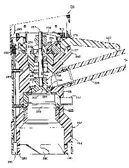
In FIGURES 14-25, an alternate preferred embodiment of
the integrated, cooperating, interlocking, liquid flow
controlling system of the present invention is fully and
completely detailed. In this embodiment, integrated,
cooperating, liquid-flow controlling system 210
incorporates liquid transfer assembly 211 and liquid
delivery/filling assembly 212.
As is fully detailed below, in this embodiment,
integrated, cooperating, liquid-flow controlling system 210
provides a liquid transfer assembly 211 which is incapable
of being activated unless telescopically mounted in the
precisely desired securely engaged relationship with liquid
delivery/filling assembly 212. In addition, liquid
transfer assembly 211 must be securely interlocked with
liquid delivery/filling assembly 212 in the precisely
desired position in order to enable the transfer of the
desired liquid.
- 44 - 302-331-6
Furthermare, once mounted in interlocked interengage-
ment, liquid transfer assembly 211. is incapable of being
disconnected from liquid delivery/filling assembly 212
while liquid is flowing through the system. Only after the '
liquid flow has been stopped and positive disconnection
steps taken, can liquid transfer assembly 211 be removed
from liquid delivery/filling assembly 212.
In this alternate preferred embodiment, liquid
delivery/filling assembly 212 incorporates an interlocked
feature which prevents the unwanted opening of the liquid
delivery/filling assembly when not desired. In this way,
assurance is provided that the liquid being transferred
into container 200, as well as dispensed from container 200
into a desired reservoir, is not accidentally spilled or
released in any unwanted area, through accidental opening
of liquid d~livery/filling assembly 212.
Before detailing the construction and operation of this
embodiment of integrated, cooperating, liquid flow
controlling system 210, reference should be made to
FTGURE 13, wherein one preferred manner of use of this
invention is depicted and the importance of achieving a
completely trouble-free controlled dispensing system for
toxic chemicals is evident.
~o~~~o~
" '~5 " 302-331-6
As discussed above, the distribution of many liquid
products has resulted in spillage of undesirable or toxic
materials into our environment, causing potential hazards
or damage to the environment, including people and animal
life living in the area. In view of the increasing
potential hazard that has existed ,From these unwanted
chemical spillages, attempts have been made to develop a
system which would eliminate this hazard. As depicted in
FIGURE 13, the present invention eliminates all of the
problems that have existed in the prior art and provides a
substantially completely full-proof, integrated,
cooperating liquid flow controlling system which assures
that the liquid being transferred at each and every step in
the transferral process is executed in a virtually
spill--free, error-free, controlled manner.
Although many alternate chemical or liquid product
distribution systems exist wherein the integrated,
cooperating, liquid flow controlling system of the present
invention can be employed, FIGURE 13 depicts the use of the
flow controlling system of the present invention in the
controlled, spill-free distribution of chemicals typically
employed in agricultural or farming environments. As
detailed above, such chemicals are often employed for
- 46 - 302331-6
promoting the growth of the agricultural products and/or
controlling the attack of such products by insects or
disease.
As shown in FIGURE 13, holding tank 215 represents a
large concentrated chemical holding tank located at a
distribution center at which individuals desiring to obtain
the chemical would come with smaller, partable containers
200. As has been detailed above, liquid delivery/filling
assembly 212 is 'preferably securely affixed to container
200 in order to prevent its unauthorized removal.
Consequently, by employing this distribution system, the
farmer oY customer requiring or desiring 'to employ the
particular chemicals could only have container 200 filled
at an authorized distribution center wherein mating,
integrated, cooperating liquid transfer assembly 211 is
available for telescopic, secure, lacked, mounted
interengagement with liquid delivery/filling assembly 212,
in order to fill or refill container 200 with the desired
chemical.
As diagrammatically depicted in FIGURE 13, hose or
conduit 216 is employed to transfer the desired chemical or
liquid from holding tank 215 to liquid transfer assembly
211, while conduit 217 is employed to transfer the
- 47 - 302-331-6
displaced air. from container 200 into holding tank 215,
where it can be safely handled, depending upon its
environmental impact.
Once container 200 has been filled with the desired
concentrated chemical, or liquid, t:he user is ready to
employ the chemical in the proper manner. xn order to
assure that proper, spill-free use of the chemical is
attained, liquid delivery/filling assembly 212 has the
construction detailed below and cooperates, in this
preferred embodiment, with a supply tank adaptor 220.
As is more fully detailed below, supply tank adaptor
220 is preferably mounted in supply tank 218 into which the
user would place a measured amount of the chemical or
liquid from container 200 and then dilute the chemical or
liquid for application to the particular site in the
authorized manner. However, by employing the specially
designed filler unit 220, assurance is provided that flow
controlling system 210 of this invention is operated in the
precisely desired manner, with all chemical transfer being
completely controlled and spill-free:
Once the chemical or toxic liquid from container 200
has been placed in supply tank 218 and diluted in the
proper manner, the user is ready to apply the precisely
- 48 - 302-331-6
desired, environmentally safe chemical in -the authorized
manner. In addition, once all of the chemical contained in
container 200 has been used in its entirety, the user
merely returns to the distribution outlet to have container
200 refilled in the manner detailed above.
In this way, a completely closed loop, environmentally
safe distribution system is attained where each and every
chemical transferral step is achieved in a manner which
assures a spill-free, environmentally safe chemical
transfer. In this way, the hazard or potential hazards
which have previously existed are eliminated. Furthermore,
by employing container 200 with sealed liquid
delivery/filling assembly 212 mounted thereto, with
container 200 purposefully constructed for re-use as the
only vehicle by which the desired chemicals can be
obtained; unwanted discarding of empty containers is
eliminated and further environmental pollution is avoided.
Consequently, it is readily apparent that the
distribution system of the present invention, with the
integrated, cooperating liquid flow controlling system
detailed herein eliminates all of the prior art
environmental hazards which have previously existed. In
addition, the present invention provides an environmentally
~~4~~~~
- 302.-331-6
safe system in which any chemical or liquid having a
potentially environmental hazard associated therewith can
be safely distributed and used, without incurring any
negative impact on the environment.
By referring to FIGURES 1~4 and 16-22, along with the
following detailed disclosure, the construction and
operation of this alternate preferred embodiment of liquid
transfer assembly 211 can best be understood. In this
construction, liquid transfer assembly 211 comprises a
housing 225 which incorporates two separate and distinct
flow channels 226 and 227 formed therewith. Preferably,
flow channel 226 comprises an enlarged flow channel
extending from housing 225 which is positioned for easy,
secure, mating engagement with the supply conduit, which is
connected to the supply tank, as detailed above. Flow
channel 227 is preferably substantially smaller and is
employed as the air passage conduit connectable with the
air line, as detailed above.
As best seen in FIGURES 19: and 16, liquid transfer
assembly 211 incorporates a readily accessible, easily
employable handle portion 230, preferably extending from
top 233 of housing 225. In addition, the support arm 231
also extends from top 233 of housing 225, preferably
- 50 - 302-331-6
positioned diametrically opposed to handle portion 230 and
radially extending outwardly from housing 225. In
addition, in the preferred construction, support arm 231
comprises a generally "L-shaped" configuration.
Liquid transfer assembly 211 also comprises a movable,
flow controlling lever 232 which, a:~ is detailed below, is
employed to initiate and terminate the flow of the liquid
through transfer assembly 211. In the preferred configura-
tion, support arm 231, flow controlling lever 232, and
enlarged liquid flow channel 226 are vertically aligned in
substantially the same axial plane, radially extending from
housing 225. In this way, ease of movement of lever 232
and control over the flow of the chemical through liquid
transfer assembly 221 is assured, and any accidental
movement of flow control lever 232 is substantially
eliminated.
By employing this construction, the user is easily able
to move liquid transfer assembly 211 by grasping handle
portion 230 in one hand and support arm 231 in the other
hand. In this way, complete movement and control of liquid
transfer assembly 211 is assured. Furthermore, by merely
reaching downwardly, the operator is able to grasp flow
controlling lever 232 and activate lever 232 whenever the
- 51 ° 302-331-6
flow preventing mufti-functional interlocking system has
been properly activated.
One of the principal achievements attained by liquid
transfer assembly 211 of this invention is the achievement
of a flow controlling, interlock system which requires
liquid transfer assembly 211 to be securely positioned in
mating, interlocked engagement with liquid delivery/filling
assembly 212 in the precisely desired orientation, before
flow controlling lever 232 is able to be lifted to initx.ate
the flow of the chemical into the desired container.
Consequently, unwanted accidental spillage of the chemical
is virtually eliminated.
In this way, liquid transfer assembly 211 achieves a
complete, full-proof liquid flow controlling system wherein
unwanted and undesirable spillage of the liquid is
avoided. In addition, any possibility that the system
could be used by~unauthorized indiv-ideals is eliminated.
As a result, complete, controlled transferral of toxic
liquids or chemicals is attained.
By referring to FIGURES 16-22, along with the following
detailed disclosure, the construction and operation of this
safety interlock flow controlling system can best be
understood. In this preferred construction, liquid
~0~~~(~~
- 52 - 302°331-6
transfer assembly 211 incorporates a flow activation switch
234 mounted along a side surface of housing 225. With
activation switch 234 in the off position, as depicted in
FIGURES 16 and 17, movement of flow controlling lever 232
is prevented. Consequently, unauthorized or improper
activation of flow controlling lever 232 is eliminated
since individuals unfamiliar with the system would be
unaware of the requirement that switch 234 must be moved
from its "off'° or locked position to its "on" or disengaged
position.
As best seen in FIGURES 17, 18, 21 and 22, flow control°
Zing lever 232 incorporates a substantially open rectangular
frame portion 235 positioned in the top of housing 225 of
liquid transfer assembly 211. Frame portion 235 peripheral-
ly surrounds and controllably engages a cam rocker 274
which lowers a valve assembly which controls the flow of
the liquid. All of these components are detailed below.
In addition, frame portion 235 of lever 232
incorporates a boss 236 extending at the forward end
thereof. Furthermore, boss 236 is positioned between two
upstanding posts 237 and supportingly retained therebetween
by pivot pin 238 extending between both posts 237,
supportingly maintaining boss 236. In this way, lever 232
is pivotable about the axis defined by pin 238.
2~~~~09
- 53 - 302-331-6
In order to enable switch 234 to be able to maintain
lever 232 in a locked, immovable position, activation
switch 234 controllably engages a movable plate 240 which
is peripherally surrounded and retained in cover 243
mounted to housing 225. One terminating end of movable
plate 240 is positioned directly adjacent frame portion 235
of lever 232.
In the preferred construction, movable plate 240
incorporates an elongated finger portion 241 extending from
one end of plate 240 directly adjacent lever 232. In
addition, lever 232 incorporates a finger receiving recess
formed therein and positioned for cooperation with finger
portion 241.
As is depicted in FTGURES Z7 and 18, when switch 234 is
in the ''off" or locked position (FIGURE 17), finger portion
241 is engaged within the finger receiving recess of lever
232. As a result, movement of lever 232 is prevented and
activation of the flow is incapable of being achieved.
However, when switch 234 has been moved from its "off" or
locked position to its "on'° or open position, as depicted
in FIGURE 18, finger portion 241 is disengaged from the
finger receiving recess of lever 232, and lever 232 is now
able to be raised for activation of the desired flow.
- 54 - 302-331-6
Although this single lever activation switch would be
capable of providing some degree of certainty that liquid
transfer assembly 211 is used properly, the present
invention incorporates further interlock systems to
substantially increase and enhance the operation of liquid
flow assembly 211 and provide positive, substantially
complete assurance that liquid transfer assembly 211 is
activated 9.nto its flow permitting position only when
complete, secure, locked interengagement with liquid
delivery/filling assembly 212 is properly attained.
Part of this further enhanced interlocking assembly is
best understood by referring to FIGURES 17-22, along with
the.following detailed disclosure. As is evident from
these figures, movable plate 240 also incorporates a second
finger portion 244, which extends from the opposite end of
movable plate 240 and is positioned in juxtaposed, spaced,
cooperating relationship with stop bracket 246.
In the preferred construction, stop bracket 246
comprises a substantially "U" shape, with the base thereof
securely affixed to the proximal end of elongated rod 247.
In addition, a spring member 248 is mounted to the opposed,
top surface of bracket 246, thereby biasing the entire
assembly downwardly, with the bottom surface of bracket 246
~fl~~~flfl
- 55 ° 302-331-6
being normally maintained in contact with. support platform
239 of housing 225. 7Cn addition, in this normal biased
position, the distal end of elongated rod 247 extends
outwardly from housing 225.
In a similar construction, cam means 245 is mounted at
its base to elongated rad 249 with spring means 250
positioned about elongated rod 249 directly adjacent the
base of cam means 245 on one side and platform 239 on the
opposed side, thereby normally biasing rod 243 and cam
means 245 upwardly, into hauling 225.
As is apparent from the drawings, both elongated rods
247 and 249 axe mounted in housing 225 of liquid transfer
assembly 212 in juxtaposed, spaced, parallel relationship
to each other, as well as in parallel relationship with the
central axis of housing 225. In addition, in the dis-
connected configuration, as depicted in FIGURES l4 and 21,
the distal end of elongated rod 247 extends outwardly from
housing 225. Since spring means 24F3 is mounted on the top
of '°U-shaped" stop bracket 246, bracket 246 is maintained
in contact with platform 239, and the terminating distal
end of elongated rod 247 is continuously maintained in its
fully extended position, unless counteracted by another
force.
~a~~~~~
-- 56 - 302-331-6
In the preferred construction of the second rod
assembly, spring member 250 is positioned between the base
of cam means 245 and platform 239, thereby maintaining cam
means 245 in its raised position, with elongated rod 249
maintained within housing 225, unt~.l cam means 245 has been
forced by movable plate 240 to move' in a downward
direction, causing the terminating distal end of elongated
rod 249 to extend out of housing 225.
As fully depicted in the drawings, activation switch
234 cannot be moved from its "off'° position to its '°on"
position until liquid transfer assembly 211 has been
mounted into secure, locked, complete interengagement with
liquid delivery/filling assembly 212. As shown in FIGURES
17 and 19, when liquid transfer assembly 212 is
disconnected from liquid delivery/filling assembly 212, the
upper portion of "U-shaped" stop bracket 246 prevents the
complete movement of switch means 234 from its "off"
position to its "on" position.
As depicted therein, the leading edge of finger portion
244 directly abuts stop bracket 246, thereby preventing the
movement of plate 240 by switch means 234. As a result,
when liquid transfer assembly 211 is disconnected from
~~9~.~~~9
57 - 302-331-6
liquid delivery/filling assembly 27.2, any individual
attempting to activate or employ lever 232 is prevented
from doing so and liquid flow cannot be achieved.
Consequently, unwanted or unauthorized dispensing of the
liquid connected to liquid transfer assembly 211 is
prevented.
Whenever liquid transfer assembly 211 is mounted to
liquid delivery/filling assembly 212, one surface of narrow
cylindrical wall 294 of liquid delivery/filling assembly
212 (F7:GURES 15, 23 and 24) contacts the terminating end of
elongated rod 247, causing rod 247 to be axially moved
upwardly into fully retained engagement within housing
225. This axial movement is in opposition to the forces
caused by spring 248 and causes stop bracket 246 to be
raised, bringing recess zone 253 of "U-shaped" stop bracket
246 into alignment with finger portion 244 of plate 240.
Once in its fully raised position, finger portion 244
is capable of being moved into recess zone 253 of stop
bracket 246, thereby enabling switch 234 to be moved from
its "off" position to its "on°' position. As is clearly
evident from this disclosure, flow controlling lever 232
can only be activated. by the movement of switch 234 from
its "off" position to its "on" position, when the entire
2~~~. ~~~
- 5f3 - 302-331-6
liquid transfer assembly 211 has been mounted to liquid
delivery filling assembly 212 in a mated, interengaged
configuration.
As a further enhancement and positive protection for
providing complete assurance that liquid transfer assembly
211 is fully and completely lockingly interengaged in mated
connection with liquid delivery/fillling assembly 212, prior
to enabling lever 232 to be activated, elongated rod 249
must be positioned in one of a plurality of rod receiving
zones 255 formed in cylindrical wall 294 of liquid
delivery/filling assembly 212. As clearly shown in EI:GURE
23, rod receiving zones 255 are formed in liquid
delivery/filling assembly 212 at various locations
representing the alternate positions at which liquid
transfer assembly 211 could'be properly securely lockingly
interengaged with liquid delivery/filling assembly 212 for
proper dispensing of the chemicals or liquids from the tank
to the container.
As is evident from the foregoing discussions, before
switch 234 can be moved from its "of~" position to its "on"
position, finger portion 244 must be moved into nested
engagement within recess 253 of stop bracket 246. However,
- 59 - 302-331-6
before finger portion 244 can enter recess zone 253, plate
240 must contact cam means 245, and cause cam means 245 'to
move downwardly against the biasirng force of spring 250
when liquid transfer assembly 211 is mounted to liquid
delivery/filling assembly 212, recess zone 253 is moved
upwardly into alignment with finger portion 244.
If liquid transfer assembly 211 has not been properly
positioned in locked interengagement with liquid delivery
filling assembly 212, none of the pin receiving recesses
255 will be in alignment with elongated pin 249. Under
these conditions, switch means 234 cannot be moved since
plate 240 will engage cam means 245 and be unable to move
cam means 245 and rod 249 vertically downwardly, since
elongated rod 249 is not positioned in vertical alignment
with a rod receiving zone 255 of liquid delivery/filling
assembly 212.
Of course, when liquid transfer assembly 211 as
properly mounted in secure locked interengagement with
liquid delivery filling assembly 212, switch 234 can be
quickly and easily moved from its '°off" position to its
'°on" position, with movable plate 240 causing the
terminating distal end of pin 249 to be moved into
- 60 - 302-331-6
engagement with rod receiving zone 255 of 7.iquid
delivery/filling assembly 212, whi:Le finger portion 244
enters recess 253 of stop bracket 246. Once in this
position, lever 232 can be activated, whenever desired, in .
order to fill the container to which liquid
delivery/filling assembly 212 is securely affixed.
It should also be evident from this disclosure that
whenever liquid transfer assembly 211 is securely and
properly mounted to liquid delivery/filling assembly 212,
and liquid flow has been initiated, accidental. or
purposeful removal of liquid transfer assembly 211 from
liquid delivery/filling assembly 212 is impossible. As
detailed above, before lever 232 can be activated, causing
liquid flow to occur, the terminating end of elongated rod
249 is pasitioned in secure engagement with a rod receiving
zone of liquid delivery/filling assembly 212.
Consequently, disengagement of liquid transfer assembly
211 from liquid delivery/filling assembly 212, while flow
is occurring, is completely prevented. As a result,
unwanted disconnection of integrated, cooperating liquid
flow controlling system 210 of this invention is pxovided
and spillage during the dispensing operation is completely
avoided.
~~~~~0~
- 61 - so2-3~1-6
As best seen in FIGURES 21 and 22, housing 225 of
mating, interlocking, liquid trans:~er assembly 211
incorporates an upper valve and lever retaining body
portion 260, a central body portion 261, and a peripherally
surrounding, depending wall portion 262, which extends from
central body portion 261 in a direction opposite from upper
body portion 260. Preferably, upper body portion 260,
central body portion 261 and wall portion 262 are formed
substantially in their entirety from a single, integrated
component and are manufactured from material which is best
suited to be unaffected by the liquid being dispensed.
At the juncture between upper body portion 260 and
central body portion 261, liquid flow channel 226 is
positioned for delivering the desired liquid to housing 225
for being dispensed at the proper time. In order to assure
that the liquid transferral occurs only when precisely
desired, valve assembly 265 is mounted in housing 225.
In the preferred embodiment, valve assembly 265
incorporates a movable valve plate 266 which is
controllably movable along the central axis of housing 225
by axially disposed elongated rod 267. Preferably, the
distal end of elangated rod 267 is securely affixed in
valve plate 266, thereby controlling the axial movement of
plate 266.
~U~~~09
- 62 - 302-331-6
In addition, coil spring means 268 is preferably
mounted about elongated rod 267 and maintained under
compression, biasirigly forcing valve plate 266 into secure,
liquid flow stopping engagement with valve receiving/seating
surface 269 of housing 225. Furthermore, in order to
assure that no liquid is capable of penetrating between
valve plate 266 and valve receiving/seating surface 269, a
sealing ring 270 is mounted to valve plate 266 fox being
brought into contacting, sealing engagement with valve
seating surface 269.
With the liquid flow channel 226 positioned directly
above valve plate 266 and valve seating surface 269, any
liquid flowing in through flow channel 226 is prevented
from being dispensed, due to the sealed engagement between
valve plate 266 and valve seating surface 269. In
addition, a centrally disposed plug 272 is mounted in upper
portion 260 of housing 225 for maintaining spring 268 under
compression, while also assuring continuous, liquid flow
preventing interengagemant between valve plate 266 and
valve seating surface 269. Tn addition, plug 271 also
prevents any chemical or toxic liquid entering through
passageway 226 from being dispensed or leaked out of
housing 225.
~~~1J~~
63 - 302-331-6
Tn order to enable lever 232 to controllably activate
or initiate the chemical or toxic liquid flow, when
desired, lever 232 is constructed for controlling 'the axial
movement of elongated rod 267. In order to attain this
precise, dependable, trouble-free control, cam rocker 274
is mounted in upper body portion 26U of housing 225 with a
port9.on thereof peripherally surrounding and retainingly
engaging elongated rod 267. 2n addition, one end of cam
rocker 274 is pivotally mounted to upstanding posts 275 by
pin means 276.
Furthermore, control pin 277 extends through cam rocker
274, with the terminating ends thereof engaged within an
arcuate slot formed in frame portion 235 of lever 232.
Finally, in order to assure controlled movement of elongated
rod 267 by cam rocker 274, a cam following nut is threadedly
engaged with rod 267, with the cam surface thereof in
sliding, contacting engagement with cam racker 274.
By employing this construction, the upward movement of
lever 232, when able to be activated as detailed above,
causes frame portion 235 of lever 232 to be lifted upwardly
in the same direction. Since elongated pin 277 is captured
by frame portion 235, the movement of lever 232 also causes
elongated pin 277 to be similarly raised.
- 64 - 302-331-6
Since pin 277 extends through cam rocker 274, the
movement of control pin 277 causes cam rocker 274 to pivot
relative to post 275 about the axis defined by pin 276.
This movement of cam rocker 274 causes cam nut 278 to be
moved therewith, simultaneously drawing elongated rod 276
upwardly in the idewtical direction. With the distal end
of elongated rod 267 threadedly mounted valve plate 266,
the upward movement of rod 267 causes valve plate 266 to
also be moved upwardly, against the biasing forces of
spring 268, disengaging the surface thereof from valve seat
269 and enabling the chemical or toxic liquid to flow
therebetween. This open position is depicted in FIGURE 22.
Central body portion 261 incorporates a through hole
formed therein in which flow channel 227 is securely
affixed. In this way, the air exiting the container into
which the fluid is being dispensed is controllably
channeled so as to assure its proper disposal, if
necessary. In addition, in the preferred embodiment,
sealing ring 279 is mounted in the internal diameter of
central body portion 261 for cooperative, sealing
interengagement with slidable collar 285 of liquid
delivery/filling assembly 212. Sealing ring 279 provides
further assurance that no chemical or toxic liquid is
~~~~~a~
- 65 - 302-331-6
capable of being accidentally leaked from the integrated,
cooperating, liquid flow controlling system 210 of this
invention.
In the preferred construction of this embodiment, as
with the alternate embodiment detailed above, wall portion
262 comprises a substantially hollow cylindrical shape
which terminates at it,s lower end with a plurality of
slotted rod locking fingers 280. Each of the elongated,
slotted fingers 280 of wall portion 262 are constructed for
mating, locked interengagement with finger receiving rods
296 formed on liquid delivery/filling assembly 212. In
this way, secure, interlocked, interengagement of liquid
transfer assembly 211 with liquid delivery/filling assembly
212 is assured.
Finally, the construction of liquid transfer assembly
211 is completed by mounting a substantially cylindrically
shaped flange member at the lower end of wall portion 262
directly adjacent elongated, rod capturing fingers 280. As
clearly depicted in FIGDRES 21 and 22, cylindrical flange
member 282 cooperates with rod capturing fingers 280 to
form an angular recess zone 283 therebetween. Furthermore,
the terminating distal end of elongated rod 247 and rod 249
is positioned in recess 283. Due to the narrow dimension
2~~~a~~
- E6 - 302-331-6
provided for annular recess zone 283, an operator is
incapable of inserting his finger to move rod 247 upwardly,
to enable switch 234 to be activated. Consequently,
further protection is provided over unTaanted or purposeful
activation of lever 232 when not lockingly interengaged
with liquid delivery/filling assembly 212 in the desired
manner.
In FIGURES 15 and 23-25, a further alternate embodiment
of the liquid delivery/filling assembly of this invention
is depicted. In this embodiment, liquid delivery/filling
assembly 212 is constructed in the substantially identical
basic configuration detailed above in reference to the
alternate embodiments shown and disclosed herein. In fact,
if desired, the alternate embodiments detailed above could
be employed directly with integrated, mating liquid
transfer assembly 211, provided the interlocking
enhancement discussed above are incorporated therein.
In addition to the incorporation of rod-receiving zones
255 in liquid delivery/filling system 212, as detailed
above, this embodiment of liquid delivery/filling assembly
212 alsa incorporates a positive activation lock system to
prevent the unwanted or unauthorized opening of liquid
delivery/filling assembly 212. In order to assure that
~(9~~.J~9
- 67 - 302-331-6
liquid delivery/filling assembly 212 is in mated
interengagement with either liquid transfer assembly 211 or
an appropriately constructed tank or reservoir, slidable
collar 285 incorporates a plurality of movable actuators
286 which must be moved simultaneously in order to enable
collar 285 to be moved axially for opening liquid
delivery/filling assembly 212.
Tn this preferred embodiment, a locking plate 288 is
mounted about tube 289 and incorporates a plurality of
upstanding flanges 290. Each upstanding flange 290 is
formed to extend inwardly, so that the terminating end of
each flange 290 abuts the underside of slidable collar
285. As a result, in its unactivated configuration, as
depicted in FIGURE 24, slidable collar 285 cannot be
axially moved downwardly, due to the engagement of
upstanding flange 290 with collar 285 and actuators 286.
Before slidable cellar 285 can be axially moved along
tube 289 to open liquid delivery/filling assembly 212, each
of the flanges 290 must be moved outwardly, so that its
terminating end does not interfere with the movement of
slidable collar 285. As clearly shown in FIGURES 24 and
25, this requisite outward movement is achieved by
simultaneously pressing each actuator 286.
~~~~J09
- 68 - 302-331-6
In this embodiment, each actuator 286 comprises an
upstanding contact post 287 normally extending upwardly in
collar 285 and connected to cam block 292 by pin 293. In
this normal position, depicted in ;FIGURE 24, flange 290
contacts cam block 292, preventing movement of collar 285
and maintaining post 287 in its raised position.
Whenever post 287 is pushed downwardly, against the
spring forces of flange 290, the flange engaging surface of
cam block 292 contacts the terminating end of flange 290,
causing flange 290 to be moved outwardly away from the
bottom surface of slidable collar 285. When fully moved
downwardly, collar 285 is free to move axially. This open
position is shown in FIGURE 25.
In the preferred embodiment, three actuator assemblies
186 are employed in order to prevent purposeful activation
of the liquid delivery/filling assembly 212 when not
properly interconnected with a mating component. By
employing at least three actuator assemblies, substantial
difficulty is encountered if manual activation is
attempted. Consequently, any purposeful or accidental
attempt to open liquid delivery/filling assembly 212 is
virtually eliminated.
- 69 ° 302-331°6
Directly adjacent the positioning of locking plate 288,
container engaging sealing cap 297. incorporates a
cylindrically shaped upstanding wall 294, the top surface
of which incorporates the rod receiving zones 255. In
addition, directly adjacent upstanding wall 294 recess zone
295 is formed with a plurality of pins 296 radially mounted
therein.
In this embodiment, the width of recess zone 295 is
slightly greater than the thickness of locking fingers 280
of liquid transfer assembly 211, thereby allowing locking
fingers 280 of liquid transfer assembly 211 to
telescopically enter recess zone 295 and, when rotated in
the proper direction, engage pins 296 in secure locked
engagement. Furthermore, when aligned in a precisely
desired locked intarengaged position, at least one of the
post receiving zones 255 is aligned with elongated pin 249
for secure, locked interengaged receipt thereof.
In addition, upstanding cylindrical wall 294 comprises
a thickness which enables upstanding wall 294 to matingly
engage within annual recess 283 of liquid transfer assembly
211. As detailed above, narrow annular recess 283 is
constructed for telescopically receiving cylindrical wall
294 and enable wall 292 to cause elongated rod 247 to be
~~~~~Q~
70 ° 302-331--6
moved upwardly, thereby enabling switch 234 to be activated
in the manner detailed above.
As is apparent from the preced:~.ng disclosure, the
present invention attains a fool--proof, interlocking,
integrated liquid flow controlling system which virtually
eliminates any spillage of the liquid being dispensed. By
employing this invention, liquids of any type or
composition can be safely dispensed in an unpressurized,
gravity-free system with complete safety.
In FIGURES 26 and 27, a preferred embodiment for a
supply or reservoir tank adaptor or insert is depicted. As
previously detailed above in reference to the alternate
embodiments of this invention, the liquid delivery/filling
assembly of this invention can be employed with any desired
tank or reservoir to dispense the desired liquid from the
container to the reservoir for use or dilution. However_
in order to assure complete trouble-free, spill-free
transferral of the liquid from the container to the tank or
reservoir, tank insert 220 is preferred. In particular,
when liquid delivery/filling assembly 21.2 is employed, with
the interlock feature detailed above, tank insert 220 is
preferred to assure mating contacting engagement with
actuators 286 of assembly 212.
~~~1W~
- 71 - 302-331-6
As depicted in FTGURES 25 and 26, tank adaptor or
insert 220 comprises an outer housing 301 and a mating,
telescopically engaged, co-axially aligned cylindrical tube
member 302. Tn the preferred embodiment, housing 301
comprises a hollow cylindrical shape and incorporates an
enlarged flange/collar 303 formed an one end thereof.
Flange/collar 303 preferably incorporates a conical surface
extending from the top of collar 303 extending into the
central open zone of housing 301. This conical surface is
constructed for mating, interengagement with liquid
delivery/filling assembly 212.
Housing 301 of insert 220 also incorporates
substantially enlarged open zones 305 formed therein,
enabling the easy transferral of displaced air
therethrough. Finally, the base of housing 301
incorporates a tube receiving upstanding ring 306 forming
the opposed terminating end of housing 301 and providing a
receiving and holding portal for tube member 302.
As depicted, cylindrical tube 302 is positioned within
the central aperture of ring 306 for concentric, co-axial,
sliding movement therein. Furthermore, in order to assure
that cylindrical tube 302 is captured within housing 301,
both ends of cylindrical tube 302 incorporate enlarged
20~~1~~
" ~2 - 302-331-6
terminating end flanges 310 and 311 peripherally
surrounding tube 302, preventing the axial withdrawal of
tube 302 from upstanding ring 306.
In the preferred construction, collar engaging flange
310 of tube 302 comprises flexible liquid sealing material
which peripherally surroundes tube 302 and is constructed
for mating, sealing, interengagement with the central
aperture 315 of flange/collar 303. In addition, spring
means 318 is mounted between sealing flange 310 and ring
306 of housing 301 for continuously urging and biasingly
maintaining telescopically movable cylindrical tube 302 in
sealed engagement with aperture 315 of flange/collar 303.
In normal use, supply tank insert 220 is maintained in
its sealed position, with sealing flange 310 of cylindrical
tube 302 continuously maintained in sealing interengagement
with portal 315 of flange/collar 303. Whenever the supply
tank is to be refilled, with the desired chemical or
liquid, liquid delivery/filling assembly 212 is quickly and
easily, inserted into position in mating, cooperating
engagement wit3a flange/collar 303 of insert 220.
If the liquid delivery/filling assembly being employed
incorporates the locking actuators detailed above, the
contacting engagement of the actuators witty the conical
~0~~~0~
- 73 - 302-331-6
surface of collar 303 automatically causes the actuators to
disengage the locking flanges, enabling liquid
delivery/filling assembly 212 to be activated. In
addition, simultaneously with the activation thereof,
cylindrical tube 302 of insert 220 is axially moved
inwardly, enabling the liquid to flow through the central
aperture of cylindrical tube 302 in the precisely desired
completely controlled manner, while the displaced air exits
through enlarged open zones 305 into the container through
the liquid delivery/filling assembly 212.
It will thus be seen that the objects set forth above,
among those made apparent from the preceding description,
are efficiently attained and, since certain changes may be
made in the above article without departing from the scope
of the invention, it is intended that all matter contained
in the above description or shown in the accompanying
drawings shall be interpreted as illustrative and not in a
limiting sense.
It is also to be understood that the following claims
are intended to cover all of the generic and specific
features of the invention herein described, and all
statements of the scope of the invention which, as a matter
of language, might be said to fall therebetween.
Having described our invention, what we claim as new
and desire to secure by Letters Patent is: