Sélection de la langue

Search

Sommaire du brevet 2041750 

Énoncé de désistement de responsabilité concernant l'information provenant de tiers

Une partie des informations de ce site Web a été fournie par des sources externes. Le gouvernement du Canada n'assume aucune responsabilité concernant la précision, l'actualité ou la fiabilité des informations fournies par les sources externes. Les utilisateurs qui désirent employer cette information devraient consulter directement la source des informations. Le contenu fourni par les sources externes n'est pas assujetti aux exigences sur les langues officielles, la protection des renseignements personnels et l'accessibilité.

Disponibilité de l'Abrégé et des Revendications

L'apparition de différences dans le texte et l'image des Revendications et de l'Abrégé dépend du moment auquel le document est publié. Les textes des Revendications et de l'Abrégé sont affichés :

  • lorsque la demande peut être examinée par le public;
  • lorsque le brevet est émis (délivrance).
(12) Demande de brevet: (11) CA 2041750
(54) Titre français: TUYAU CHAUFFE PAR UN CONDUCTEUR ELECTRIQUE
(54) Titre anglais: ELECTRICALLY HEATED HOSE
Statut: Réputée abandonnée et au-delà du délai pour le rétablissement - en attente de la réponse à l’avis de communication rejetée
Données bibliographiques
(51) Classification internationale des brevets (CIB):
  • H05B 03/00 (2006.01)
  • B60S 01/48 (2006.01)
  • H05B 03/58 (2006.01)
(72) Inventeurs :
  • HOPPERDIETZEL, SIEGFRIED (Allemagne)
  • HOPPERDIETZEL, SIEGFRIED (Allemagne)
(73) Titulaires :
  • REHAU AG AND CO.
(71) Demandeurs :
  • REHAU AG AND CO. (Allemagne)
(74) Agent: MOFFAT & CO.
(74) Co-agent:
(45) Délivré:
(22) Date de dépôt: 1991-05-02
(41) Mise à la disponibilité du public: 1991-11-03
Licence disponible: S.O.
Cédé au domaine public: S.O.
(25) Langue des documents déposés: Anglais

Traité de coopération en matière de brevets (PCT): Non

(30) Données de priorité de la demande:
Numéro de la demande Pays / territoire Date
G 90 04 980 (Allemagne) 1990-05-02

Abrégés

Abrégé anglais


ABSTRACT OF THE DISCLOSURE
An electrically heated hose, particularly for heating
vehicle windshield washer systems, including a heating
conductor arranged longitudinally in the interior of the
hose. The heating conductor is a coaxial conductor having
a center electrical conductor, a conductive braided wire
structure conductively connected at a first end with the
center electrical conductor but otherwise separated from
the center electrical conductor by an insulating layer, and
an outer liquid-tight electrical insulating layer disposed
on the conductive braided wire structure. The second end
of the coaxial heating conductor extends out of said hose
via a liquid-tight seal where a plug-in element, for
connection to a current source, is connected to the center
electrical conductor and to the conductive braided wire
structure.

Revendications

Note : Les revendications sont présentées dans la langue officielle dans laquelle elles ont été soumises.


THE EMBODIMENTS OF THE INVENTION IN WHICH AN EXCLUSIVE
PROPERTY OR PRIVILEGE IS CLAIMED ARE DEFINED AS FOLLOWS:
1. An electrically heated hose, particularly for
heating vehicle windshield washer systems, comprising:
a hose having first and second ends and defining an
interior conduit;
a heating conductor arranged in said interior conduit of
said hose, extending along a length of said hose, and having
a first end which extends out of said interior conduit of
the hose adjacent said first end of said hose via a liquid-
tight seal, said heating conductor being a coaxial conductor
including a center electrical conductor, an electrical
insulating layer disposed around said center conductor, a
conductive braided wire structure disposed on said electrical
insulating layer and electrically connected to said center
electrical conductor at the second end of said heating
conductor, and a liquid-tight outer insulating layer; and
a plug-in connector, f or connection to a current
source, electrically connected to said electrical conductor
and to said conductive braided wire structure at said first
end of said heating conductor and outside of said interior
conduit of said hose.
- 9 -

2. An electrically heated hose as defined in claim 1,
wherein said coaxial heating conductor extends along
substantially the entire length of said conduit.
3. An electrically heated hose as defined in claim 1,
wherein said hose includes at least one branch opening along
its length.
4. An electrically heated hose as defined in claim 1,
wherein said liquid-tight seal is disposed at said first end
of said hose.
5. An electrically heated hose as defined in claim 1,
wherein said heating conductor further includes a thermal
insulator disposed between said liquid-tight outer insulating
layer and said conductive braided wire structure.
6. An electrically heated hose as defined in claim 1,
wherein said electrical conductor and said conductive braided
wire structure each comprises copper.
- 10 -

Description

Note : Les descriptions sont présentées dans la langue officielle dans laquelle elles ont été soumises.

20~ 7~
BACgGROUND OF T~E INVENTION
This invention relates to an electrically heated hose,
particularly for heating vehicle windshield washer systems,
including a heating conductor for transporting the thermal
energy to the washing fluid contained in the interior of the
. 10 hose, with the heating conductor having electrical terminals
and being an insulated unit that extends longitudinally in
the interior of the hose.
German Gebrauchsmuster ~Utility Model) No. 86/07,830
discloses an electrical heating device for the washing fluid
in vehicle windshield washer systems. In this device, the
heating wire lies as an insulated conductor in the interior
of the hose carrying the washing fluid. It has been found to
be a drawback of this system that it requires two wires,
namely the actual heating wire and the return wire, to.be
arranged next to one another in the interior of the hose. In
order to conduct current, this requires two current carrying
terminals at each input and output, involving a complicated
connection technique in which the system must be interrupted
-- 2 --

20~17~
repeatedly in order to form branches or other connections.
This drawback becomes particularly apparent if branch nozzles
and similar elements are involved.
SUMI~ARY OF THE INV~TION
It is therefore an object of the invention to avoid the
above-described drawbacks and to provide a hose heating
system which, in addition to being easily manufactured,
involves an uncomplicated connection technique.
- This object and others to become apparent as the
specification progresses, are accomplished by the invention,
according to which, briefly stated, the heating conductor is
configured as a coaxial conductor having a copper conductor
in its interior, a conductive braided wire structure which is
separated therefrom by an insulating layer, as well as an
external insulation. The copper conductor and the braided
wire structure are electrically connected with one another in
the region of one end of the hose, and at the other free end
of the hose the heating conductor is brought out of the hose
in a sealed manner. The copper conductor and the braided
wire structure are combined, while being insulated from one
another, in a plug-in member which can be connected with a
current source by a simple plug-in process.
-- 3 --

2~ 75~
The advantages of the invention are that only one
compact conductor (or cable) is disposed in the water in the
interior of the hose. The heating conductor projects only
from one end of the hose and simple T-branches can be
employed for branch nozzles. It is therefore not necessary
to interrupt the system to establish the branches, and the
heating system can be employed without complication for
hoses, fluid containers, and the like.
BRIEF DESCRIPTION OF l~EIE DRAWINGS
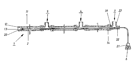
Figure 1 is a schematic sectional elevational view
showing a hose conduit, provided with branches, and a heating
conductor according to a preferred embodiment of the
invention.
Figure 2 is a cross-sectional view of the heating
conductor of Fig. 1.
Figure 3 is a schematic view illustrating the connection
at one end of the heating conductor of Fig. 1.
Figure 4 is a schematic view illustrating the connection
at the other end of the heating conductor.

2~4~7~
DESCRIPTION OF T~E PRE]FERRED ENBODINENT
Figure 1 shows a hose conduit 1 including a coaxial
heating conductor 2 disposed in its interior 11. At one free
end 12, hose conduit 1 is tightly sealed by a closure element
13. At its other free end 14, a stub 31 of a T-shaped
connecting member 3 is tightly inserted into the interior 11
of the hose. Stub 31 extends in the axial direction of
connecting member 3 and changes into a likewise axially
extending stub 32. A stub 33 projects on the side in the
middle between the two axially extending stubs 31 and 32.
One end of the heating conductor 2 leaves the interior 11 of
hose conduit 1 via the end of stub 32 which is sealed in a
known manner.
Hose conduit 1 is provided with further T-shaped
connecting members 4, 5 which are distributed over its
length. These connecting members 4, 5 may have the same
configuration as connecting member 3. Each one of the
members 3, 4, 5 is a simple hose connection, which, in
addition to being a T-shaped connecting member as shown, may
additionally be configured as an axial connector, as a Y-
shaped connector, or the like. These connecting members may
be connected, for example, directly with nozzle openings (not
shown) for spraying out washer fluid onto, for example, the

2~ 7~
windshields of motor vehicles or may be connected with other
connections.
The end of heating conductor 2 coming out of interior 11
of the hose conduit 1 is connected by a plug-in connector 21
with a current source 6. At the end 22 of the coaxial
conductor, i.e. in the region of the free end 12 of hose
conduit 1, a copper conductor and conductive plaited wires of
the conductor 2 are electrically connected with one another
and this conductive connection is covered by an insulating
layer, as described in greater detail below.
Figure 2 is a cross-sectional view of the heating
conductor 2. As considered from the inside out, heating
conductor 2 includes a stranded copper wire center conductor
23 that is surrounded by an electrical and thermal insulation
24 made of, for example, polyamide, and heating conductor
wire in the form of a conductive braided wire structure 25
disposed on insulation 24. This conductive braided wire
structure 25 may be, for example, a copper wire braid. A
thermal insulation 26, which may be, for example, glass silk,
is in turn disposed on braided wire structure 25. The entire
structure is encased in a bending-resistant and water-tight
insulation 27, for example, of polyamide.
Figure 3 shows the conductive connection of copper
conductor 23 and the braided wire structure 25 at the end 22

~ ~ 4 ~ rG~ ~ ~
of the conductor 2 in the region of free hose end 12. In
Fig. 3, the water-tight insulation 27 and the thermal
insulation 26 at the end 22 have been removed. Moreover, the
insulation 24 has also been removed at the end 22, e.g., by
previous lifting of conductive braided wire structure 25
away from the further structure, and the braided wire
structure 25 directly applied and soldered to the copper
conductor 23. The free end 22 of thermal conductor 2 iS then
encased in a water-tight insulation 28.
Figure 4 shows the connection of copper conductor 23 and
the conductive braided wire structure 25 to the plug-in
connector 21. At this end, the insulation 26, 27 has been
removed from copper conductor 23 and conductive braided wire
structure 25 as described in connection with Figure 3 .
Then, copper conductor 23 is electrically connected with a
short plug-in pin 211, and conductive braided wire structure
25 is electrically connected with a long plug-in pin 212.
Plug-in pins 211, 212 are then insulated electrically and
thermally against one another and the entire structure is
encased in a bend resistant and water-tight insulation 28'.
It will be understood that the above description of the
present invention is susceptible to various modifications,
changes, and adaptations, and the same are intended to be
-- 7 --

-
2~7~0
comprehended within the meaning and range of equivalents of
the appended claims.
... ... .

Dessin représentatif
Une figure unique qui représente un dessin illustrant l'invention.
États administratifs

2024-08-01 : Dans le cadre de la transition vers les Brevets de nouvelle génération (BNG), la base de données sur les brevets canadiens (BDBC) contient désormais un Historique d'événement plus détaillé, qui reproduit le Journal des événements de notre nouvelle solution interne.

Veuillez noter que les événements débutant par « Inactive : » se réfèrent à des événements qui ne sont plus utilisés dans notre nouvelle solution interne.

Pour une meilleure compréhension de l'état de la demande ou brevet qui figure sur cette page, la rubrique Mise en garde , et les descriptions de Brevet , Historique d'événement , Taxes périodiques et Historique des paiements devraient être consultées.

Historique d'événement

Description Date
Inactive : CIB de MCD 2006-03-11
Le délai pour l'annulation est expiré 1993-11-02
Demande non rétablie avant l'échéance 1993-11-02
Réputée abandonnée - omission de répondre à un avis sur les taxes pour le maintien en état 1993-05-03
Inactive : Demande ad hoc documentée 1993-05-03
Demande publiée (accessible au public) 1991-11-03

Historique d'abandonnement

Date d'abandonnement Raison Date de rétablissement
1993-05-03
Titulaires au dossier

Les titulaires actuels et antérieures au dossier sont affichés en ordre alphabétique.

Titulaires actuels au dossier
REHAU AG AND CO.
Titulaires antérieures au dossier
SIEGFRIED HOPPERDIETZEL
Les propriétaires antérieurs qui ne figurent pas dans la liste des « Propriétaires au dossier » apparaîtront dans d'autres documents au dossier.
Documents

Pour visionner les fichiers sélectionnés, entrer le code reCAPTCHA :


Pour visualiser une image, cliquer sur un lien dans la colonne description du document. Pour télécharger l'image (les images), cliquer l'une ou plusieurs cases à cocher dans la première colonne et ensuite cliquer sur le bouton "Télécharger sélection en format PDF (archive Zip)" ou le bouton "Télécharger sélection (en un fichier PDF fusionné)".

Liste des documents de brevet publiés et non publiés sur la BDBC .

Si vous avez des difficultés à accéder au contenu, veuillez communiquer avec le Centre de services à la clientèle au 1-866-997-1936, ou envoyer un courriel au Centre de service à la clientèle de l'OPIC.


Description du
Document 
Date
(aaaa-mm-jj) 
Nombre de pages   Taille de l'image (Ko) 
Abrégé 1991-11-02 1 20
Revendications 1991-11-02 2 46
Dessins 1991-11-02 3 33
Description 1991-11-02 7 162
Dessin représentatif 1999-07-18 1 7