Note : Les descriptions sont présentées dans la langue officielle dans laquelle elles ont été soumises.
1
,..,.
~J4~924
A METHOD FOR DETERMINING THE TRANSMISSION QUALITY OF A HOME
TRAFFIC CONNECTION IN A MOBILE RADIO SYSTEM
TECHNICAL FIELD
The present invention relates to a method for determining a
transmission quality of a home traffic connection in a mobile
radio system,
wherein
- the mobile radio system includes two-way radio channels, each
having two carrier frequencies at a desired frequency distance
from one another ;
- the home traffic connection, which i:~ established between a
base station and a subscriber mobile station, utilizes an
indicated one of the radio channels; and wherein
- the indicated radio channel can be used within the mobile radio
system by further subscribers as traffic connections whose radio
signals are liable to interfere with the radio signals of the home
traffic connection.
BACKGROUND ART
In a cell-divided mobile radio system, the geographic regions of
the system are divided into cells which are collected into larger
groups, often referred to as clusters. Each cell is allocated a
number of carrier frequencies in accordance with a frequency plan,
so that mutually adjacent cells will not disturb one another and
so that a carried frequency pattern can be formed in the group.
Each cell may have a base station, and it is also possible to serve
several cells from a single base station. The pattern of carrier
frequencies is then repeated with each group. A mobile radio
system of this kind is described in more detail in CMS88, Cellular
Mobile Telephone System, Ericsson Telecom, 1988, Chapter 6.
In an adaptive mobile radio system, each base station is able to
transmit on all carrier frequencies and the channels are allocated
to a mobile station subsequent to having established the extent to
which the separate carrier frequencies are disturbed. As the
2 241924
channels are allocated, there forms a changing geographic pattern
of carrier frequencies which are so allocated that no one connec-
tion will disturb the other. Channel allocation is normally
effected with the aid of a control channel. on a carrier frequency,
and traffic signals are transmitted on traffic channels of other
carrier frequencies. When the number of carrier frequencies is
limited, it is extremely difficult to avoid disturbances between
separate connections which use one and the same carrier frequency.
Among other things, this difficulty is because the mobile stations
are liable to have a disturbing effect of varying magnitude when
they move. Various methods have been proposed for creating a mea-
surement of the quality of a connection, for instance with the aid
of SAT (Supervising Audio Tone) as described in the aforesaid
reference CMS88, Chapter 1:10. The base station transmits on a
desired carrier frequency a tone which has a modulation frequency
above the audible range. The tone is received by the mobile
station and retransmitted to the base station. The base station
can determine the extent to which the selected carrier frequency
is disturbed, by comparing the transmittE:d tone with the retrans-
mitted tone. In the case of digital transmission systems, the Bit
Error Rate, BER, can be used as a measurement of the disturbance.
The drawback with both of these methods, however, is that they
give an indirect measurement of how the carrier frequency from a
disturbing connection influences the home connection.
In a thesis submitted at the Royal Institute of Technology (Kungl.
Tekniska Hogskolan) by Christer Gustavsson and entitled "Simuler-
ing av adaptivt kanalval" (Simulation of Adaptive Channel
Selection) , Ericsson Radio Systems AB, 1987, there is described a
method of reducing the number of calls which are blocked when
changing base stations, for instance. The base stations have, in
the main, permanently allocated channels, but they also have a
smaller number of adaptive channels. The base station and the
mobile station measure the signal strength on the call channels of
the system and use these measurements as a measurement of the
signal strength of traffic channels which can be connected. The
mobile station and the base station also measure the signal
strength of traffic channels between foreign mobile stations and
CA 02041924 2000-11-24
3
base stations. These traffic channels constitute
disturbances on the connection to be established. There is
selected a traffic channel whose disturbance has a low signal
strength in relation to t:he signal strength of the call
channel. Although the method enables the transmission
quality of a traffic connection to be adequately assessed and
also provides for an adequate choice of traffic channel, it
does not provide a direct: measurement of the signal strength
of the selected traffic channel, which :is a disadvantage.
Neither does the method provide the possibility of measuring
continuously the transmi~~siori quality o:E the home traffic
connection that has been established. A similar method of
determining transmission quality has been proposed for the
European mobile telephon~~ system. This method is described
in ETSI/GSM 05.08, Version 3.5.0, Chapter 3.
DISCLOSURE OF THE INVENTION
The inventive method avoids the aforesaid drawbacks
associated with known techniques. The :invention is based on
the concept of measuring the signal strength of the carrier
frequency of the home traffic connection and also the signal
strength of the carrier frequency of disturbing traffic
connections over a time interval in which the carrier
frequency of the home connection is closed down.
According to the present. invention there is provided a
method for determining a transmission quality of a home
traffic connection in a mobile radio system, where the mobile
radio system includes two-way radio channels, each channel
having two carrier frequencies at a desired frequency
distance from one anothE=_r: the home tra:Efic connection, which
is established between a first base station and a first
CA 02041924 2000-11-24
3a
subscriber mobile station, utilizes a first radio channel;
and wherein the first radio <:hannel can be reused within the
mobile radio system by a second base station and another
subscriber mobile station as a. traffic connection whose radio
signals are liable to interfere with the radio signals of the
home traffic connection at tree first base station, comprising
the following method steps: measuring, at a first location,
the combined received signal strength (C+I) of the carrier
frequencies on the first radio channel during the
transmission of speech ox- data; measuring, at the first
location, the signal strength of an interfering carrier
frequency (I) on the fir~~t radio channel in a. time interval
during which the carrier frequency of the home traffic
connection is closed down; and calculating the transmission
quality as the quotient (C/I), where (C) is the signal
strength of the carrier frequency of the home traffic
connection and (I) is the signal strength of the interfering
carrier frequency.
BRIEF DESCRIPTION OF THE DRAWINGS
An exemplifying embodiment of the :invention will now be
described in more detail with reference to the accompanying
drawings, in which
Figure 1 illustrate~~ cells and cell-groups of a mobile
telephony system;
Figure 2 illustrate: schematically signal paths and
disturbances between base stations and mobile stations;
4 ~~~1~2~
Figure 3 illustrates time slots and signal strengths for a time-
shared mobile telephony system; and
Figure 4 illustrates a time slot signal sequence.
BEST MODE OF CARRYING OUT THE INVENTION
Figure 1 illustrates schematically the geographic dividing of a
cellular mobile radio system. A cell 1 having a base station BS1
is included in a cell group 3. The mobile telephony system is
allocated a frequency band which has been divided into a number of
channels, for instance 400 separate channels. The mobile system
has a fixed frequency plan and each cell :in the group 3 has access
to a smaller number of the channels, for instance 20 channels for
each cell. The 400 channels are so distributed within the cell
group 3 that any one channel having a given pair of carrier
frequencies will only occur once. This counteracts interchannel
disturbance. A cell 2 having a base station BS2 belongs to an
adjacent cell group 4, which has access to the 400 channels in a
corresponding manner. The base station BS2 has access to the same
channels as the base station BS1 and these base stations are
spaced as far apart as possible, so as to avoid disturbances to the
greatest possible extent. A more detailed description of cell
division and frequency plans is given in the aforesaid reference
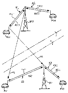
CMS88, Chapter 6. Figure 2 illustrates the base station BS1 with
mobile stations MS1 and MS3 within the cell 1, and the base station
BS2 with mobiles MS2 and MS4 within the cell 2. The base station
BS1 has a traffic connection with the :mobile MS1 on a traffic
channel K1, which includes an outgoing cYiannel FVC1 from the base
station and an incoming channel RVC1 t~o the base station. The
mobile MS3 establishes a traffic connection to the base station
BS1 with the aid of a control channel K3 with an outgoing control
channel FOCC and an incoming control channel RECC. The base
station BS2 has a traffic connection with the mobile MS2 on the
channel K1 and with the mobile MS4 on a channel K2, which includes
an outgoing channel FVC2 and an incoming channel RVC2. The
channels lie in the 800 MHz-band and the frequency difference of
the carrier frequency between outgoing and incoming channels is 45
MHz for all channels, both the traffic channels and the control
~~4~.~24
channels. The frequency difference between two mutually adjacent
channels is 30 kHz.
There is some risk that the channel K1 in the cell 1 will be
disturbed by interferences from channel K1 in cell 2 , despite the
5 long distance between the base stations B1 and B2, as mentioned
above with reference to Figure 1. The object of the present
invention is to provide a method for measuring and determining the
transmission quality of the home traffic connection on channel K1
between the base station BS1 and the mobile station MS1. More
specifically, the transmission quality is determined as the
quotient of C/I, where the magnitude C i:a the signal strength of
the carrier frequency of the channel K1 between the base station
BS1 and the mobile MS1 and where the magnitude I is the combined
interfering signal strength of carrier frequencies for the channel
K1 when the connection between the base station BS1 and the mobile
station MS1 is closed. In the illustrated case, this interfering
signal strength originates from the connection between the base
station BS2 and the mobile station MS2 , although other connections
(not shown) on the channel K1 can also contribute to the strength
of the interfering signal.
Figure 2 illustrates an interfering signal F1 passing from the
base station BS2 to the mobile MS1, and an interfering signal R1
passing from the mobile MS2 to the base station BS1. The quality
of the transmission is determined in the following manner,
provided that F1 and R1 are the only interfering signals. The
mobile MS1 measures the combined signal strength C+I of the
outgoing channel FVC1 from the base stations BS1 and BS2. When the
carrier frequency of the outgoing channel. FVC1 from the home base
station BS1 is closed, the mobile MS1 measures the strength I of
the interfering signal FI. The quality of the transmission is then
calculated as (C+I) /I -1 = C/I. The base station BS1 measures the
combined signal strength C+I of the incoming channel RVC1 from the
mobile MS1 and MS2 in a corresponding manner. When the carrier
frequency of the incoming signal RVC1 from the mobile MS1 is
closed, the base station BS1 measures the strength I of the inter-
fering signal RI. According to the present invention, only one of
6
~4~.92~
the base stations or one of the mobiles stations measures the
signal strengths and the result obtained for C/I is exchanged
between the stations.
In the case of the aforedescribed method, a problem exists in
measuring the signal strength I of the carrier frequency for the
interfering signal, represented by the signals FI and RI respec-
tively in the illustrated example. This measurement shall be taken
when the carrier frequency on the home traffic connection is
closed and, according to one embodiment, the problem is solved in
the following manner. In order to save battery power, the trans-
mitter, normally the mobile MS1, is equipped with a device for
closing the carrier frequency. This is done during a time interval
in which no modulated signal is delivered to the transmitter. The
subscriber only listens, and no information is transmitted to the
base station BS1 on the carrier frequency of the channel RVC1. The
base station BS1 measures the strength I of the interfering signal
RI during these silent intervals. The device used to close down
the carrier frequency is well known to those skilled in this art
and will not be described in detail. The receiver, i.e. the base
station BS1, can ascertain that solely the interfering signal RI
has been measured, by listening on the aforesaid SAT-signal. If
the carrier frequency of the mobile is closed, the SAT-signal
transmitted by the base station is not re-transmitted. This
supervisory signal occurs in a solely frequency-shared mobile
radio system, a FDMA-system. A corresponding supervisory signal,
normally referred to as a DVCC-signal (Digital Verification Colour
Code) occurs in a' time-shared radio system.
In a time shared system, the base station. can listen to the DVCC
signal in a corresponding manner, so as to determine when the
carrier frequency of the mobile MS1 is closed.
In a time-shared mobile telephony system, the strength I of the
interfering signal can also be measured :in the following manner.
Each carrier frequency is divided into a number of time slots, for
instance in accordance with the exempli fying time slots TS1, TS2
and TS3 shown in Figure 3. Traffic is found on the time slots TS1
and TS3, as illustrated by a curve A in the Figure, where the
magnitude C denotes the signal strength of the carrier frequency
and T denotes time. Information concerning the ongoing traffic is
stored in the base station BS1. The base station measures the
strength of the interfering signal RI at time points T1, T2, T3 and
T4 over the duration of the time slot TS2, which is silent. The
interfering signal RI also includes the three time slots desig-
nated TS11, TS12 and TS13, which are not synchronized with the
time slots TS1, TS2 and TS3. There is, however, some correlation,
between the distubance in the silent time slot TS2 and the
disturbance in the trafficated time slots TS1 and TS3. By measur-
ing at repeated time points, as illustrated in the Figure, there
is obtained a measurement of the strength I of the interfering
signal RI, which is also relevant to the trafficated time slots
TS1 and TS3. A corresponding measuring procedure can be effected
from the mobile MS1, which receives from the base station BS1
information as to which time slots are trafficated. This infor-
mation is transmitted on the traffic channel, the time slot TS1,
as illustrated in Figure 4. The time slot TS1 from the base station
BS1 includes a signal sequence which includes a synchronizing
sequence SYNC, a control sequence SACCH ('Slow Associated Control
Channel) , a data sequence DATA containing the speech transmitted,
the aforesaid DVCC-signal, and a sequence RSVD (Researd) which can
be used for any desired purpose. The control sequence SACCH can be
utilized for transmitting the aforesaid information to the mobile
MS1 relating to trafficated time slota. When measuring the
interference I outside the home time slot, measurements are
advantageously taken on several occasions, for instance at the
time points T1, T2 , T3 and T4 in Figure 3 , in order to enable the
interference value to be well calculated. Such repeated measure-
ments are particularly important when measuring from the base
station BS1, since the disturbances originate from cells
peripheral of mobile stations. The mobile stations are randomly
distributed over the cell areas and are movable, and statistical
processing of the interference measurements obtained is
advantageously carried out.
The signal sequence from the base station BS1 illustrated in
Figure 4 provides the mobile MS1 with a further possibility of
~~4~9~4
measuring the interference I. The base station BS1 can interrupt
the transmission of its carrier frequency in one of the time slots
TS1 during the sequence RSVD, and the mobile MS1 can measure the
interference I during this sequence. The base station BS1 sends to
the mobile in the preceding time slot TS1, during the sequence
RSVD, a message to the effect that the carrier frequency from the
home base station has actually been closed, so that the mobile
will be prepared to measure the interference. It is also possible
for the mobile to measure the signal strength continuously during
the signal sequence RSVD and subsequently receive from the base
station a message to the effect that the carrier frequency in RSVD
was actually closed down throughout the duration of the preceding
time slot.
A further example of how the interference I can be measured is
described below. It is possible for the mobile or the base station
to interrupt the carrier frequency during the whole of a time
slot, even though information should normally have been trans-
mitted in this time slot. The strength I of the interfering signal
is measured by the receiving station during this time slot. In
this case, a message is exchanged between the base station and the
mobile station, so that the receiving station will be informed of
the fact that the carrier frequency of the: transmitting station is
closed down. This message can be transmitted on the signal SACCH
in Figure 4. In the future European mobile telephony system GSM,
there is space in the signal sequence for the mobile to order the
base station to close its carrier frequency. The drawback with
this method is that information which should have been exchanged
between the stations in the closed time ,lot is lost and the bit-
error content increases.
The aforedescribed method enables the signal quality of the home
traffic connection to be determined by measuring and calculating
the quotient C/I. This value constitutes a valuable measurement
since, for instance, it enables a decision to be made as to whether
the mobile needs to hand-over, i.e. pass from one channel to
another. The method has the advantage of being based on direct
measurement of partly the signal strength C of the home carrier
..w g ~;4~~~4
frequency and partly the signal I of the interfering signal. It
should be noted that the C/I-value used in accordance with the
invention does not replace other measurements of transmission
quality, for instance bit-error content, but complements these
measurements. This circumstances are demonstrated by thefollowing
example.
The total disturbance on the channel FVC1 to the mobile MS1 shown
in Figure 2 is, among other things, composed of the aforesaid
interference I, noise and multipath propagation. Multipath
propagation results from the fact that the base station BS1 is
able to reach the mobile MS1 partly through direct signals, as
indicated in Figure 2, and partly through signals reflected from
buildings, surrounding hills and the likE~. The reflected signals
are delayed in relation to the direct signals and the multipath
propagation contributes in increasing the bit-error content. When
the signal strength C is sufficiently high, a high bit-error
content can be due to strong interference I or pronounced mul-
tipath propagation. In order to reduce the bit-error content, the
mobile MS1 can either shift to a new channel from the home base
station BS1 or to a new base station, for instance the base station
BS3 in Figure 1. In this situation, an adequate choice can be made
with the aid of the inventive C/I-value. If this value is high, the
large bit-error content is most probably due to multipath
propagation. A change of channel with the home base station BS1
will not change the propagation conditions of the signals and will
likely not affect the bit-error content. A switch to a new base
station is the best choice in this case. If, on the other hand, the
C/I-value is low, the large bit-error content is most probably due
to the fact that the interference I is strong, implying that a
change of channel with the home base station BS1 is more than
likely to be the best choice for reducing the bit-error content.
In the case of a time-shared system, t:he interference I, and
therewith the bit-error content, can be reduced by switching to a
new time slot on the same carrier frequency.