Note : Les descriptions sont présentées dans la langue officielle dans laquelle elles ont été soumises.
1 Background of the Invention
A prothetic finger joint for replacing the proximal-
interphalangeal (PIP) or distal-interphalangeal (DIP) finger
joint is known from US Patent Specification 4,725,280. There,
the proximal member of the joint is formed of a shell-shaped
element made of plastics material or a chromium-molybdenum
alloy and mounted on the correspondingly prepared bone end of
the proximal or middle phalanx. The distal member of the joint
is made of plastics material and includes a body that forms a
bearing surface for the other joint member, and a shaft to be
embedded into the medullary cavity of the phalanx bone.
In the distal joint member, the bearing body is formed as
a massive head so that considerable resection of the bone is
necessary. On the other hand, permanent fixation of the shell-
shaped proximal joint member on the respective bone end isproblematic. Further, the two cooperating bearing surfaces of
the known joint prosthesis are shaped such that it is always
necessary to replace the entire joint.
Gexman Patent Specification 976,768 discloses a prosthe-
tic joint member which includes a bearing body forming a bear-
ing surface, and a shaft to be embedded in the bone, wherein
the bearing body is formed as a thin-walled shell portion
having a bearing surface shaped after the natural form. The
entire prosthesis is made of plastics material. The shaft
extends obliquely through the bone and is curved so that it
exits from the bone and engages the compact outer bone region
at a location remote from the joint surface. This type of
anchorage results in an undesirable damage and weakening of
the bone.
Summary of the Invention
It is an object of the present invention to provide a
prosthesis, particularly for a finger joint, which requires
only minimal resection of the bone and yet ensures a secure
anchorage in the bone, and which permits replacing only one
member of the joint in cases where the other member is still
functioning.
To meet this object, the prosthetic joint member of the
present invention comprises a bearing body in the form of a
1 thin-walled shell portion having a bearing surface shaped
after the natural form, and a shaft to be embedded in the
bone, wherein the shell portion is formed of high-strength
metallic material and has a maximum thickness of about 1 mm,
the bearing surface having an average roughness of no more
than about 5 ~m, and the rear surface of the shell portion
having a roughness pf about 5 ~m to about 250 ~m.
By forming the bearing body as a thin-walled but high-
strength metallic shell portion, the invention aims at replac-
ing substantially the bearing surface only. Since the shellportion has a maximum thickness of about 1 mm only, removing
the joint cartilage alone will usually suffice. The shaft pro-
vided on the rear side for anchoring the shell portion in the
medullary bone cavity, and the roughness of the rear surface
of the shell portion cooperate to provide secure and permanent
fixation and a safe adherence of the prosthetic member in the
anchoring bone cement. Since the bearing surface of the pros-
thetic joint member according to the invention is shaped after
the natural form of the joint member to be replaced, it is
further possible to replace only one member of the joint and
to maintain the other natural member provided the latter is
still functioning, as is often the case after accidental in-
juries.
In a preferred development of the invention, the bearing
surface of the shell portion is mirror-polished to provide
good sliding properties of the bearing surfaces against each
other.
In another advantageous embodiment, the shaft has a shape
formed by the surfaces of a plurality of ellipsoids or flat-
tened spheres partly penetrating each other, the maximum ratiobetween the longest and shortest axes being about 4, prefer-
ably 2. Further, the surface of the shaft has an average
roughness of about 5 ~m to about 500 ~m, preferably 10 ~m to
100 ~m. These features further improve the permanent anchorage
of the shaft in the respective bone cavity by means of a bone
cement.
In a further preferred development of the invention, the
shell portion of the proximal joint member, in the dorsal-
2~419~2
1 palmar longitudinal section, forms a semicircular arc, and theshaft connects to the shell portion at a location eccentrical-
ly offset in the dorsal direction. Similarly, the shell por-
tion of the distal joint member, in the dorsal-palmar longitu-
dinal section, forms approximately a quarter-circular arc, and
the shaft connects to the shell portion at a location eccen-
trically offset in the palmar direction. As a result of these
features, excellent mobility, particularly maximum flexion,
are achieved.
Brief Description of the Drawinqs
Figures l and 2 are side views of a prosthetic proximal
joint member and a distal prosthetic joint member, respective-
ly, as seen from the dorsal side.
Figure 2A is a longitudinal section through the distal
joint member, taken in a plane parallel to that of Figure 2.
Figures 3 and 4 are longitudinal sections through the two
prosthetic members in the plane of symmetry X-X of Figures 1
and 2.
Figures 5 and 6 are plan views of the two prosthetic
members, each taken along the axis of the respective shaft.
Detailed Description of a Preferred Embodiment
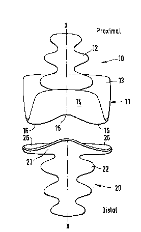
The prosthetic proximal joint member shown in Figures 1,
3 and 5 and forming the head of a finger joint consists of a
bearing body in the form of a shell portion 11 and a shaft 12
integrally formed on the inner side of the shell portion 11.
In the longitudinal section of Figure 3, the shell por-
tion 11 forms substantially a semicircular arc, and the shaft
12 is formed on the inner side of the shell portion 11 eccen-
trically offset in the dorsal direction, thereby forming a cap
portion 13 extending in the palmar direction which permits a
large flexion angle of the finger joint prothesis of at least
90, preferably about 100. As shown in Figures 1 and 5, the
palmar cap portion 13 is wider than the dorsal portion 14 of
the shell portion ll.
The bearing surface of the shell portion 11 facing the
other joint member comprises a rounded recess 15 extending in
the plane of symmetry X-X and laterally adjoining convex sur-
face portions 16. The overall form of the bearing surface is
~,~41~
1 shaped after the human finger joint in an anatomically ideal-
ized form and permits, in addition to a flexion, small lateral
motions relative to the other joint member, similar to a natu-
ral finger joint.
The thickness of the bearing shell 11 in the longitudinal
section shown in Figure 3 is no more than about 1 mm, pre-
ferably no more than 0.5 mm. The bearing surface is mirror-
polished with an average roughness of no more than about 5 ~m,
preferably no more than 2.5 ~m. On the other hand, the inner
side of the shell portion 11 has an average roughness between
about 5 ~m and about 250 ~m, with a preferred range from 10 to
50 ~m.
The bearing surface has rounded edges and corners to
avoid stress or damage on the tendons and ligaments. The
mirror-polishing achieves a high slidability on the opposite
bearing surface.
The shaft 12 has a shape formed by the surfaces of a plu-
rality of mutually partly penetrating ellipsoids or flattened
spheres, with the ratio of the longest axis shown in Figure 1
to the shortest axis shown in Figure 3 in the same cross-
sectional plane being no more than about 4, preferably 2. This
shape ensures good utilization of the elliptic cross-section
of the medullar cavity of the finger bone and simultaneously
prevents a relative rotation between the prosthesis and the
bone.
The surface of the shaft 12 has an average roughness of
more than about 5 ~m up to about 500 ~m, with a preferred
range of 10 to 100 ~m. The surface of the shaft 12 and the
inner side of the shell portion 11 have preferably the same
roughness.
For further improving the anchoring of the prosthesis in
the respective cement, the roughened surfaces of the shaft 12
and of the inner side of the shell portion 11 may be further
treated, e.g. provided with a ceramic intermediate layer which
may be additionally silanated. With a methacrylate-based ce-
ment, the use of silanes having methacrylate functionality is
advantageous. As a cement for anchoring the shaft 12 in the
bone cavity and for fixing the inner side of the shell portion
2~4~9$2
1 11, glass ionomer cements, such as cements on the base an
acid-soluble glass and a polymeric polyacid, are particularly
suitable.
The prosthetis member 10 proper is made of a high-
strength metal in order to obtain sufficient stability and
wear resistance in view of the small thickness of the shell
portion 11. Particularly suited are titanium and titanium
alloys, special steel alloys, such as chromium-cobalt-molyb-
denum based steel alloys, silver-paladium based noble metal
alloys and alloys with a high gold content. The prosthetic
member 10 is preferably manufactured by casting; other manu-
facturing methods, such as pressing, milling, erosion and
electroplating methods may be employed alternatively.
The prosthetic distal joint member 20 shown in Figures 2,
2A, 4 and 6 and forming the joint base similarly consists of a
shell portion 21 and a shaft 22 integrally formed on the rear
side of the shell portion 21. In the longitudinal section
shown in Figure 4, the shell portion 21 forms about a quarter-
circular arc, and the shaft is eccentrically offset in the
palmar direction. As will be understood from the longitudinal
section of Figure 2A and particularly from the plan view of
Figure 6, the shell portion 21 has a rounded projection 25
extending in the plane of symmetry X-X, and laterally adjoin-
ing concave surface portions 26.
The surface properties of the bearing surface of the
shell portion 21 facing the proximal joint member 10 and of
the rear side of the shell portion 21 and of the shaft 22
correspond to those described above for the prosthetic member
10. The same applies with respect to the overall shape of the
shaft 22, the material, the manufacturing method and the ce-
ment for anchoring the prosthetic member 20 in the correspond-
ing phalanx.
Example
After a master model of the bearing surface and shaft had
been made of plastics material or plaster, a negative mould
was formed using a material commercially available from the
company ESPE under the tradename REPROGUM. The negative mould
was filled with modelling plastics material commercially
~4~2
1 available from the same company under the tradename VISIO-FORM
and the plastics material model thus obtained was precisely
worked by corundum paper. The master model of the shaft was
equally formed by a material commercially available from the
same company under the tradename PERMAGUM, and a plastics
material model was prepared in this mould from methyl metha-
crylate commercially available from the company GC under the
tradename PATTERN RESIN, and subsequently worked with cordun-
dum paper. The bearing surface and shaft were fixed to each
other in the correct position by means of a cyanoacrylate
adhesive and wax commercially available from the company
SCHULER-DENTAL under the tradename TELESKOP-WAC~IS.
The cast patterns were pegged and waxed onto a muffled
base together with a "lost head" and embedded in accordance
with dentistry methods. The muffle was preheated and filled
with a casting alloy commercially available from the company
KRUPP under the tradename WISIL (which is an alloy containing
60 wt.% Cr, 30 wt.% Co and 5 wt.% Mo). After removal from the
mould, the raw cast was cleaned by sandblasting, the cast
piece (prosthesis) was separated, sharp edges were rounded,
the retention surfaces (shaft and rear side of the shell por-
tion) were sandblasted with sand of a grain size of 250 ~m to
an average roughness of 18 ~m, and the bearing surface was
mirror-polished to an average roughness of 1.3 ~m.
In a controlled clinical study, PIP prostheses were im-
planted into five patients. In three cases, the caput (phalan-
geal side) and base (distal side) were implanted. In one case,
only the phalangeal side, and in another case only the distal
side was replaced.
Only minimum resection of the joint surfaces (by means of
an oscillating saw) was required for inserting the prostheses.
A mixed glass ionomer cement commercially available from the
company IONOS under the tradename V-O CEM was subsequently in-
cluded, and the prosthesis was inserted. Upon setting of the
cement, excess cement was removed and the operation was com-
pleted by suturing, etc.
Post-operative mobility was excellent even after a period
of ten months in all five cases. The operated joints could be
flexed up to an angle of 90.