Note : Les descriptions sont présentées dans la langue officielle dans laquelle elles ont été soumises.
2 2(~ 88~
FI~LD OF TH~ INVENTION
This invention relates to apparatus for
distributing a liquid across a packed tower. The liquid
will normally be sulphuric acid or oleum. For convenience,
both will be referred to in the description and in the
claims as ~sulphuric acid~.
~AC~GROUND OF TH~ INV~NTION
Sulphuric acid plants, and cther applications
involving the drying of chlorine or sulphur dioxide,
commonly include packed towers in which concentrated
sulphuric acid is circulated over a hody of packing. Such
towers have been used for more than one hundred years, and
many different approaches to the construction of such
towers have been attempted, with varying degrees of
success.
The basic criteria that a good distribution
system must meet are (1) the need to spread the liquid
uniformly over the packing with a minimum reliance on tha
packing as a liquid spreading medium, (2) the need to
maintain good distribution regardless of acid flowj t3) the
ability of the ~e~ice to demonstrate good distribution
without complex tests, (4) the ability of the device to be
cleaned of any accumulations of sulphate, brick chips,
packing chips or other rubbish without a major maintenance
effort, and (5) resistance to corrosion and erosion such
8~3~
that good distribution is present not only when tho device
is new but also when it has eroded sufficiently to be near
the end of its life span. The device should also be
simple, easy to repair or replace/ durable, and made of
reasonably available economical materials.
An early method used to distribute acid was a
cast iron pipe distributor. This device used a central
header which fed arms which in turn had drilled holes which
allowed the acid to flow out on to ~he packing. The header
and arms were made from common cast iron fittings such as
tees, crosses and pipe. Acid velocities from the holes
were in the range of khree to six ~eet per second. Nhile
the device was relatively economical compared with other
alternatives, it blocked access to tho packing since the
pipes and header covered approximately 50 per cent of the
tower cross-section. The arrangement also required
significant mechanical support.
Other defects in the cast iron sy~tem included
the lack of erosion resistance in the cast iron which
resulted in holes sizes increasing to the point of
affecting acid distribution. There was also some tendency
for the collection of tramp ceramic, brick and sulphate
material in the arms where it co~ld not be seen and from
which it was difficult to remove.
2~Z88~
The cast iron system was later modified by the
insertion of corrosion resistant materials in the holes as
discrete inserts. Subsequently cast iron was displaced
completely by the use of very corrosion resistant materials
such as high silicone containing austenitic steels. These
materials needed no inserts since they ar~ very corrosion
and erosion resistant in strong sulphuric acid. However
these designs are still difficult to clean, and they block
a fraction of the tower cross-section which can typically
be as high as 45 per cent.
A relatively common approach in North American
practice has been to use troughs from which the acid
overflows through downcomer spouts onto the packing. Since
the spouts are open at the top, it i5 relatively easy to
see any build-up of tramp materials and to remove such
material~. However the acid distribution is then severely
dependant on the levelling of the individual troughs, the
absence of any sagging, and the absence of any entrance
efects. Acid distribution is also needed outside the
tower to ensure that each individual header receives an
apprQpriate share of the total acid flow. Th~ troughs ars
usually not corrosion resistant and replacement is
necessary from time to time. Moreover the troughs are
normally sp~cially designed fox each tower so that repair
or replacement is very difficult. The design can be
improved, but at significant cost, by using more corrosion
resistant materials. A newer version is also available in
- 5 20~ 38~
which the acid flows outwardly through submerged holes,
thus reducing the sensitivity of the device to levelling.
SUMMAR~ OF THE INVENTION
It is an ob~ect of this invention to provide
apparatus for distributing a liquid containing sulphuric
acid across a packed tower, said tower having an external
shell, said apparatus\comprising a plurality of pipe means
located in a substantially horizontal plane and each
extending across said tower, each pipe means having first
and second ends, each pipe means extending through said
shell at said first end and extending at least to a
position adjacent to said shall at said second end, said
shell having a port therein adjacent said second end of
each said pipe mean~, each pipe means further having
multiple rows of holes therein, said holes of one row being
oriented at a different angle to the vertical than the
holes o~ another row, and a body of packing in said tower,
said pipe means being spaced above said packing for said
hole~ to distribute acid onto said packing, each pipe means
having closure means removably coupled to said second end
~hereo for closing the interior of said pipe means from
the environment external to said pipe, said closure means
being located to be accessible at said ports, so that said
closure means can be removed from outside said tower fox
removal of deposits accumulated in said pipe means during
operation.
6 2i~2~3~34
Further objec~s and advantages will appear from
the following description, taken together with the
accompanying drawings.
BRIEF DESC~RIPTION OF ~ DRAli~I~GS
In the accompanying drawings:
~ig.1 shows a prior art distributor of the pipe
type:
Fig.2 is a plan view of a distributor ~ystesn
according to the present invention.
Fig.3 is a cross-sectional view of a tubular
header or pipe according to the present
invention;
Fig.4 is a partial cross-sectional view showing
the waIl of a tower containing a distributor
according to the present invention and al~o
showing detail of a clean-out arrangement; and
Fig.5 is a view similar to that of Fig.4 but
showing a modification thereof.
~` 7 2~9L2~
DETAILED DESCRIPTIOM OF PREFERRlED EMBODIMENTS
Reference is first made to Fig.l, which shows a
pipe distributor 10 according to the prior art. As shown,
an acid feed stream enters the tower 12 through an inlet
pipe 14 which carries the acid to side arms 16. Where cast
iron is used, a central header 18 is assembled from
standard tee and cross fittings 20, 22, and assembled with
side arms 16 by bolting thP flanges of the pipe and
fitting~ together. The side arms 16 project horizontally
at right angles to the header 18 and are provided with
drilled holes on each side to allow the acid to flow out
over the packing. Such holes are indicated at 24 on one of
the arms in Fig.1.
With the design shown in Fig.1, thexe are only
two rows of holes per arm and, with the limited flow por
arm, the diameter o~ the arms is small, rarely exceeding 8
inches in diameter. This size requires support both at the
centre and edge of the tower. A further inherent
characteristic of the Fig.l arrangement using cast iron is
that the space between the arms is set by the fittings
used, and typically the arms block nearly 50 per cent of
the tower cross-section. Variations of the Fig.l design
using corrosion resistant steels and other alloys allow
more flexibility in terms of arm spacing th~n with cast
iron, but the use of fewer arms to block less of the tower
8 2~14;~
cross-section results in a poorer acid distribu~ion and
hence a need for more tower packing.
It i5 also noted that when liquid enters packing
in a tower, the liquid spreads laterally from the feed
point until uniform distribution is obtained. The
spreading is relatively slow with an angle of spreading of
about 15 from the vertical. The effectiveness of the tower
packing is therefore dependant on the distance between the
feed points or the number of feed points per unit area.
The need for good distribution of liquid increases the
extent to which the Fig.1 system blocks the tower cross-
section. Blocking a large portion of the tower section has
various disadvantages, but in particular, if the
distributor is buried in the packing (which was commonly
the case), it reduces the area through which gas may rise
through the tower.
Another problem with the Fig.1 system is that
cleaning o distributors is difficult, regaxdless of
whether trough or pipe type units are used. In both cases
it is necessary to enter the tower, which is a hazardous
area because of the acid present. In the case of pipe type
units it is also necessary to undo in~ernal flanges to gain
access to tramp materials in the distributor. An important
reason for this difficulty is that present distributors are
completely contained inside the tower.
9 ~ 2~
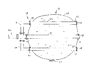
Reference is next made to Fig.2, which shows a
distributor 30 according to the invention for a tower o~
size similar to that of Fig.l (which can be up to 30 feet
in diameter). In the Fig.2 arrangement each header 32 is
5 fed from outside the tower 12. Each header feeds a number
of rows of feed points. There can for example be two,
three, four, or five or more rows of feed points for each
header 12 as will b~ described. The individual headers 32
can project through the wall 34 of the tower at their ends
remote from the feed, as indicated at 36 and as will be
described in more detail. At the ends 36 clean-out devices
or ports 38 can be provided. The ports 38 are useful for
systems which collect either debris or corrosion products.
As shown in Fig. 2, the headers 3~ also each
project through the tower at their feed ends and are
connected outside the tower to feed pipes 40 which are
locaked at the ends of the headers remote from the fre~
ends 36. Feed pipes 40 are connected to a main feed pipe
42. For removal of the headers 32, as will be described,
the feed pipes 40 are unbolted at flanges 44 from the
header 32.
It is evident from Fig.2 that the fraction of the
tower cross-3ection which is blocXed ~y the distributor 30
is much le~s than that of the classic design shown in
Fig.l, and the distributor 30 itself is much simpler.
~:~4;~8~3~
Fig.3 shows an individual header 32 which
contains holés 50a to 50e for five rows of feed points.
Tubular inserts, 52a to 52e are placed one in each hole and
project outwardly from the header to protect the holes
S a~ainst corrosion. The inserts can be made of heat
exchanqer tubing, or they can be made by casting a highly
corrosion resistant alloy. The inserts 52a to 52e can be
inserted by chilling them, inserting them and then allowing
them to warm, or they can be rolled with a tube roll.
Where tubes are used, longer sections of tube can be used
to lead acid to different parts of the tower.
Alternatively the inserts 52a to 52e can project
sufficiently to allow other conduits such as hose or tube
to be connected to them. In the exemplary arrangement shown
lS in Fig. 3, the upper inserts 52a, 52e are longer than the
next lower inserts 52b, 52d, which in turn are longer than
the bottom insert 52c. This allows good distribution of the
acid over the packing, which i~ shown at 54 as being
located below the header 32 and below inser~s S2a ~o ~2e.
Thus, there is reduced reliance on the packing itsel to
promote spreading of the liquid.
If desired, and as shown at 52f in Fig. 2, some
of the inserts can be curved to ensure liquid is spread to
all parts of the packing 54. The inserts 52a to 52f can be
of the corrosion resistant metal known as Saramet (trade
mark) or of other appropriate corrosion resistant rnaterialO
- 2(~ 2813~
11
Reference is next made to Fig.4, which shows
diagrammatically a typical arrangement for a clean-o~t port
38. In this arrangement the header pipe 32 is shown as
being formed in two sections 32a, 32b joined by flange~
60, 62 threaded thereon and bolted together ~since such
pipe is typically not available in lengths greater than 18
feet, and a 30 foot diameter tower is assumed~. The shell
or steel wall of the tower is shown at 64, lined with brick
65. The shell is flanged at 66 to form a port 67 in the
wall 64.
A large external flange 68 is fitted to the
header section 32a by threads 70. The flange 68 is also
connected by bolts 72 to a cover plate 74. The cover plate
74 acts as an access port which can be removed by removal
of bolts 72. This allows access to the interior of header
32 for visual inspection ~rom out~ide the tower, and also
for removal of the header as will be explained. The cover
plate 74 is slightly smaller .in diameter than that o~
flange 68, so that while flange 68 supports the weight at
one end of header 32 on the brick 65, the cover plate 74
can be removed for access to the interior of the header.
Access to cover plate 74 i~ obtained by removing
a second cover plate 76 secured by bolts 78 to an exterior
1ange 80. Flange 80 is connected in any desired manner,
e.g. threads, to flange 66.
12
It will be seen that the interior diameter of the
port 67 is greater than the exteriox diameter of flanges
60, 62, 68. Thi~ allows complete removal of the header
32 when required (e.g. for replacement). Such removal can
be effected (for example) by inserting a guide such as a
smaller pipe or channel into the header 32 and then
removing header 32 on such support (after of course
xemoving the cover plates 74, 76).
For cleaning without removal of the header 32
from the tower, the cover plates 74, 76 can be taken off,
and then a vacuum hose can be inserted to suck up debris~
This can be done without entering the tower, thereby
increasing operational safety.
Fig.5 shows a modi~ied arrangement in which
primed reference numerals indicate parts corresponding to
tho e of Fig.4. In the Fig.S arrangement the brick lining
for the tower is not present, and t~e flange 68' is bolted
to an annular plate 84' which in turn is bolted to the
flange 80'. The plate 84' contains a central opening 86
which allow~ access to the interior of the header 32l.
Opening 86 will normally be of the same internal diameter
as that of the header 32'. A cover plate 76' normally
covers the opening 86 and can be bolted to plate 84~ using
the same boLts 90 which secure plate 84' to flange 68';
alternatively different bolts can be used if desired.
13
It will be seen from Figs.3 and 4 that the
headers 32 are now located above the packing 54 onto which
they distribute liquid. In current practice, designers
have pxeferred not to plac~ the headers above the packing
since they were uncertain where the liquid would land on
the packing. Therefore the current practice is to bury the
headers wholly or partly in the packing. This has the
disadvantage that the exterior of the pipe cannot be
inspected or clean~d easily, nor can the distribution be
checked. With the present arrangement, inspection por~s
can be placed in the tower at appropriate locations (e.g.
as shown at 80 in Fig.2, on the same level as the headers
32) to view directly the distribution from the headers.
(It will be appreciated that although not shown, there m~y
also be further packing and further headers in the tower
above those shown.)
It is also important to note that since the
header pipe~ 32 are not located in the packing, their
cross-section is far less critical than if they were in the
packing. When the distributor i9 buried in the packing,
then at the distributor level the tower effectively has a
smaller cross section for gas and liquid flow. This may
restrict throughput and may require a larger ~ize tower.
When the pipes are outside the packing, even a relatively
large cross-section will have little effect on gas flow
through the tower. In addition, since the headers 32 ~re
spaced well apart (for example 48 inches instead of the
usual 12 inches), it is possible if necessary for a
14 ;;~ Z~38~
maintenance person to walk between the headers on top of
the packing, to clean debris from the top of the packing.
In the use of the invention, it is preferred to
employ larger diameter header pipes since this provides a
m~ch larger corrosion allowance and much lower bending
stresses than smaller size header pipe. This provides both
economic an safety advantages. There are several reasons
for this, including the following.
1. Larger pipe has thicker walls than smaller
pipe.
2. Even quality cast iron corrodes. A corrosion
rate o~ .020 inches per year is ~uite common.
3. Ca~t iron pipe requires flanging for assembly.
This requires trimming the pipe to round and then
cutting a thread on the pipe. With thicker pipe,
more wall thickness remains after cutting the
thread.
4. ~arger pipe can carry more acid and feed more
points.
5. ~igh quality cas~ iron pipe is both stronger
and more corrosion resistan~ to sulphuric
acid. The ~trength can range from 2,000 to
~o~
3,000 psi up to 10,000 psi depending on the
quality of the cast iron.
- The following tables display the inner diameter
ID ( inches), the moment of inertia MI, the running load per
inch W (pounds), the bending moment BMI and the s~ress (psi)
for various diameter pipes at various remaining wall
thicknesses ("NALL") in inches, assuming a 30 foot span.
It is assumed that the design safety factor is 2 to 1, that
the density of the cast iron is .3 lbs. per cubic inch, and
that the acid density is .0642 lbs per cubic inch.
Table 1
(6 inch O.D. pipe, D under flange = 6.225 inches)
WALL .090 .100 .llO .120 .130
15 I.D. 6.045 6.025 6.005 5.985 5.9650
Ml 8.1628 9.0260 9.8806 10.7267 11.5644
W 3.5740 3.6187 3.6633 3.7077 3.7520
BM 14475 14655.7 1~836 15016 15195
STRESS 5519 5054 4674 4357 4090
Table 2
(8 inch O.D. pipe, D under flange = 8.025 inches)
NALL .090 .100 .110 .120 .130 .140
I.D. 8.025 8.00S 7.985 7.965 7.945 7.925
~ 18.89 20.912 220918 24.glO 26.887 28.849
25 W 5.6011 5.6605 5.7197 5.779 5.8377 ~.8g~5
BM 226~4 22925 23165 23405 236~3 23881
STRESS 4926 4497 4147 3855 3609 3396
16 ~ 8
~ab1e 3
(10 inCh O.D. PiPe, D Under f1ange = 10.29 inCheS)
WALL .090 .100 .110 .120
I.D. 10.11 10.09 10.07 10.05
5 MI 37.509 41.555 45.577 49.575
W 8.2994 8.3742 8.4489 8.5234
BM 33613 33916 34218 34520
STRESS 4611 4199 3863 3583
Table 4
(12 inch O.D. pipe, D under flange = 12.25 inCheS)
WALL .090 .100 .110 .120
I.D. 12.07 12.05 12.03 12.01
Nl 63.552 70.440 77. 294 84.114
W 11.323 11.4118 11.5010 11.590
15 BM 4585~ 46218 46579 46~40
STRESS 4420 4019 3691 3418
Table 5
(14 inch O.D. pipe, D under flange = 13. 46 inches)
WALL .090 .100 .110 .120
I.D. 13.28 13.26 13.24 13.22
Ml 84.473 93.649 102.784 111.878
W 13.5204 13.~187 13.716~ 13.814g
BM 54758 55156 55553 559590
STRESS 4363 3964 3638 3366
17 ;~ 8~3~
- Table 6
(16 inch O.D. pipe, D under flange = 15.42 inches)
NALL .090 .100 .110 .120
I.D. 15.24 15.22 15.20 15.18
Ml 127.33 141.21 155.02 168.79
N 17.305 17.418 17.531 17.643
BM 70086 7~544 71001 7145
STRESS 4244 3852 3531 3264
Table 7
(18 inch O.D. pipe, D under flange = 17.40 inches)
WALL .09 .10
I.D. 17.22 17.20
MI 183.32 203.34
W 21.4246 21.552
BM 86770 87286
STRESS 4071 3735
Table 8 below is derived from the above tables
and ~hows the li~e expectancy of a header pipe versus its
size, assuming corrosion of .020 inches per year in the
internal diameter of the header pipe. It will be seen that
with the parameters 6hown, a 6 inch header pipe can be
expected to last slightly over 9 years, whi}e an lB inch
header pipe can be expected to last about 26 years. While
these rat~s will vary depending on the rate of corrosion,
it will be seen that there is a major advantage in using
larger pipe.
18 ~:~4~8~
Table 8
(pipe life vs. Size, for 4,000 psi stress)
Pipe Dia. 6 8 10 12 14 1618
5 (inches)
Wall .134 .115 .106 .100 .093 .096 .092
thickness
Original 5.957 7.975 10.078 12.050 13.262 15.228 17.216
I.D.
10 Ending 5.585 7.505 9.550 11.450 12.380 14.300 16.160
I.D.
Corrosion .3720 .470 .528 .6 .882 .928 1.056
Allowance
(dia.)
15 Corrosion .1860 .235 .264 .3 .441 .464 .528
Allowance
~radius)
Life 9.3 11.75 13.20 15 22 23.2 26.4
in years
20 (at 02
inch~s
per year)