Note : Les descriptions sont présentées dans la langue officielle dans laquelle elles ont été soumises.
204~896
PASSIVE SAFETY SHUTDOWN SYSTEM FOR NUCLEAR REACTORS
BACKGROUND OF THE INVENTION
This invention relates to nuclear reactor
components employing passive safety systems for slowing
or shutting down the nuclear reaction when the
temperature of the heat transfer fluid leaving the
reactor core exceeds a predetermined value.
It is essential to provide highly reliable
systems for safely shutting down nuclear reactors in the
event that control system failure should occur in an
unsafe manner. Any such accident could cause
overheating of fuel and release of radioactivity. It is
well known that this could pose a hazard both to the
operator and to the public. This could also damage the
nuclear plant and/or result in the loss of the
operating licence, leading to financial losses as well.
Several types of active safety shutdown
systems are known in the art. An active shutdown system
operates in response to a control signal, and normally
inserts a neutron-absorbing material into the reactor
core to stop the fission chain reaction. Such systems
generally employ electronic eguipment such as
temperature and pressure sensors, amplifiers, alarm
units, power supplies, relay logic systems, manual
controls, indicators, and computers as well as process
equipment including valves, pumps and the like. Active
systems are considered to be less reliable than passive
methods of shutdown because they are more complex and
have more failure modes. Active systems employ
redundant "trip channels" which must be monitored and
tested frequently to demonstrate that availability
targets are met. Active systems also require much more
attention by a nuclear operator which is a problem for
small reactors where operating costs must be kept low.
Safety depends on proper operator action according to
prescribed procedures and principles and hence active
systems are more susceptible to human error. Generally,
204289~
active systems are relatively costly to purchase,
install and maintain.
It will be app~rent from the above that it has '
become very desirable to provide passive safety shutdown
systems for nuclear reactors which employ phenomena and
devices which behave passively as a result of natural
properties and forces within the reactor without any
dependence on external controls and sources of power.
In order to be effective these passive systems must be
extremely reliable without the need for frequent
monitoring and testing and any other human involvement
to confirm full operability.
There are three principal types of passive
safety systems:
(A) those which do not require moving mechanical
parts nor moving working fluid;
(B) those which involve a moving working fluid,
but no moving mechanical parts; and
(C) those which depend on moving mechanical
parts.
The first type is the most preferred since it avoids
concerns about potential impairments of the required
motion such as might be ~reated by friction or leakage.
The present invention is concerned with
passive systems of the second type noted above,
involving the movement of a liquid thermaI neutron
absorber into the reactor core at a specific
predetermined temperature and under the natural force of
gravity.
~0 The prior art has provided a number of passive
shutdown systems which purport to operate when excessive
temperatures in the core of the reactor are reached.
One such system is described in Schively U.S. Patent
3,795,580 filed October 19, 1972 which refers to the
~5 use of a lithium alloy abso~ber which melts at the
required trip temperature and falls passively into the
.... ,. ~ ~ .
"
204~896
-- 3 --
core region to shut down the reaction. However, it
appears that the Schively system has a significant
disadvantage since the many hollow compartments needed
in the core to accommodate this particular system would
tend to allow a significant leakage of neutrons
outwardly of the core during normal operation thus
resulting in less than optimum fuel utilization or
requiring a larger core size. Another potential
problem with the Schively proposal is its relatively
slow response to an accident due to the time needed to
supply the heat of fusion necessary to melt the absorber
alloy at the passive trip temperature. The actual
reactor trip or shutdown could occur at a te~perature
substantially above the melting point because the
accident could progress substantially during the time
the neutron absorber is changing from the solid to the
liquid state.
It is well known that a neutron absorber
affects the neutron flux in its immediate vicinity. To
shut down a reactor adeguately the absorbers must be
inserted throughout the core. The passive safety
devices should be installed in each fuel assembly or
bundle within the core. Ideally, each safety device
must be unfailingly capable of releasing its absorber
when the local temperature exceeds the passive trip
temperature thus depressing each local flux peak until
the reactor is stabilized at an acceptable power level
or forced to shut down altogether. The safety devices
are reguired to act only in the very rare event of an
accident wherein the reactor control system has
malfunctioned unsafely and the active safety shutdown
system has not prevented the heat transfer fluid from
exceeding active trip temperature.
SUMMARY OF THE INVENTIO~
It is a general object of the present
invention to provide an improved passive safety shutdown
.
.
:, :
, .
2(~4289~
-- 4 --
system or device for nuclear reactors which is capable
of satisfying the criteria for such passive systems as
noted above.
The present invention accordingly relates to a
fuel assembly adapted to form a part of a nuclear
reactor core section, said fuel assembly including an
array of fuel pins disposed in pre-selected spaced
relation to one another. The fuel assembly is arranged
to permit a liquid heat transer medium and moderator,
(and which is referred to hereafter, and after first
mention thereof in the detailed description and claims,
simply as a heat transfer medium,) to flow upwardly in
contact with the fuel pins to remove heat therefrom. At
least one passive safety device is disposed in the fuel
assembly within the array of fuel pins. The safety
device has an upper portion lscated above the le~el of
the array of fuel pins so as to be exposed to the upward
flow of heat transfer medium which has been heated
during passage through the array of fuel pins, and a
lower portion disposed within the array of fuel pins. A
neutron absorber is normally disposed in said upper
portion of the safety device and has a melting point
such that when the temperature of the heat transfer
medium to which said upper portion of the safety device
is exposed exceeds a selected temperature, the neutron
absorber melts such that it has the capability of
flowing downwardly by gravity into said lower portion of
the safety device to absorb neutrons and depress the
neutron flux and the heat being generated in the
vicinity of the neutron absorber.
In accordance with one aspect of the
invention, the lower portion of the safety device
comprises an elongated tubular body arranged such that
it contains or is substantially filled with a neutron
moderator during normal use to reduce or prevent neutron
leakage along the safety device outwardly of the core
.
: :
.. ~,' '.: - ' ' .
,
~0~2896
-- 5 --
section.
As a further feature of the invention, the
tubular body noted above may be vented so that it is
filled with the liquid heat transfer medium when in
normal use to reduce the neutron leakage along the
safety device. In this situation the neutron absorber
is of a material which does not react chemically with
the heat transfer medium. When the safety device is
activated by an over-temperature condition, the
downwardly flowing neutron absorber displaces the liquid
outwardly of the tubular body so that the latter becomes
filled to the required level with the neutron absorber
material.
In an alternate form of the invention, the
above-noted tubular body may be provided with an axially
arranged rod of moderator material disposed therein such
that an annular space is provided between the rod and
the tubular body to receive and contain the molten
neutron absorber flowing downwardly from the upper
portion of the safety device in response to an over-
temperature condition. This alternative is used in
situations wherein the neutron absorber material would
react with the liquid heat transfer medium and hence
under normal circumstances the above-noted annular space
is filled with an inert gas such as helium.
In both of the alternatives described above,
during normal operation, the liquid filled tubular body
or, alternatively, the rod of moderating material, acts
to scatter the neutrons hence reducing losses of
neutrons from the core along the safety device and thus
enhancing the efficiency of the reactor as compared, for
example, with the above-noted Schively arrangement.
In accordance with a further aspect of the
invention, said upper portion of the safety device
defines a compartment for holding the neutron absorber,
said compartment having a lower exit opening through
- ~ .
.; . ~' . . : ~
2~2~396
-- 6 --
which the molten neutron absorber can flow by gravity.
In a preferred form of the invention a fuse element of
relatively small mass as compared with the mass of the
neutron absorber is disposed in said exit opening, said
fuse element having a higher melting temperature than
does the body of neutron absorber in said compartment so
that when the temperature of the heat transfer medium
exceeds a first predetermined temperature below the trip
temperature the body of neutron absorber melts but is
retained in the compartment by the fuse element, said
fuse element being arranged to melt at the trip
temperature such that when the latter is reached the
exit opening is unblocked and the previously melted
neutron absorber flows down into said lower portion of
the safety device.
The advantage of the system described above is
that it provides a very rapid response time as compared,
for example, with the Schively system. Since the fuse
is of relatlvely small mass, it melts fairly quickly
once the trip temperature is reached thus allowing the
previously melted and much larger mass of neutron
absorber to move downwardly by gravity into the lower
portion of the safety device.
Typically, fins are provided on the exterior
of the above-noted compartment so as to enhance the rate
of heat transfer from the liguid heat transfer medium
into the neutron absorber within this compartment.
In accordance with a still further aspect of
the invention, said safety device is arranged such that
it can be inserted endwise into each fuel assembly from
above with shoulder means and fastener to define the
axial location of the safety device within the fuel
assembly, and an interlock means to secure the safety
device against inadvertent withdrawal from the fuel
assembly when it is in the core section, said interlock
being inaccessible from above the core section such that
':
204;~89fi
-- 7 --
the fuel assembly must be removed from the reactor
before the interlock can be released and the safety
device then removed from the fuel assembly.
In a preferred form of the invention, the
interlock means includes a release element which
normally projects below a lower portion of the fuel
assembly and is arranged such that depression of same
occurring on placement of the fuel assembly on a surface
after removal from the reactor effects release of the
interlock and allows withdrawal of the safety device
from the fuel assembly.
Various metals are suitable for use as the
neutron absorber. Several suitable eutectic alloys are
referred to hereafter. These are of course selected in
accordance with their neutron absorbing characteristics
and their melting points. Certain pure metals may also
be suitable depending upon the melting temperature
required.
The principles of the present invention are
applicable to a wide variety of reactors provided that
these reactors are ones in which accidents can only
occur relatively slowly, i.e. in excess of a few
minutes. The present system is not contemplated for use
in reactors wherein accidents can occur quickly such as
in certain pressurized power reactors wherein a serious
failure can occur within seconds, as for example in the
event of breakage of a pressurized pipe. These systems
require fast shutdown arrangements which are designed
to insert shutoff rods or a liquid absorber very
rapidly.
Preferred embodiments of the invention will
now be described with reference to the accompanying
drawings.
BRIEF DESCRIPTION OF VIEWS OF DRAWINS
Fig. 1 is a longitudinal section view of a
typical nuclear fuel assembly with the passive safety
- ~ -
. .
~ - :
20~;2 89fi
-- 8 --
device positioned therein;
Fig. 2 is a horizontal cross-section view of
the fuel assembly of Fig. 1 with the passive safety
device positioned therein;
Fig. 3 is a view similar to that of Fig. 1 and
partially in section with a somewhat modified form of
passive safety device in position;
Fig. 4 is a cross-section view of the fuel
assembly and passive safety device as illustrated in
Fig. 3; and
Fig. 5 is a diagrammatic plan view of a
typical reactor core layout showing the individual fuel
assemblies, control absorbers and the like.
DETAILED DESCRIPTION OF_?HE PREFERRED EMBODIMENTS
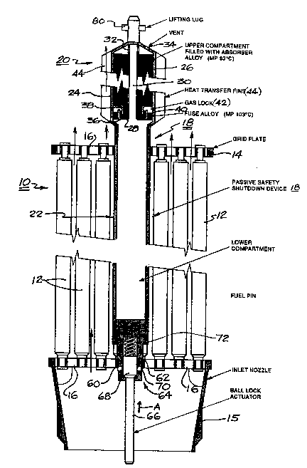
Referring firstly to Figs. 1 and 2 there is
shown a fuel assembly or bundle 10 for use in a nuclear
reactor core section, the fuel bundle 10 including a
multiplicity of fuel pins 12 each connected to and
extending between a spaced apart parallel grid plate 14
and inlet nozzle assembly 15. The grid plate and
nozzle assembly 15 are provided with a large number of
closely spaced flow openings 16 thereby to permit a
liquid heat transfer medium and moderator to flow
upwardly in contact with the fuel pins 12 to remove the
heat therefrom which is generated by the nuclear
fission reaction.
In one particular reactor arrangement as
illustrated in Fig. 5 (~nown as the AECL SES-10 reactor)
each fuel pin 12 has a diameter of about 13 mm, the fuel
pins being disposed in an 8X8 array as best seen in Fig.
2 with the outside dimensions of the array being
approximately 140 mm x 140 mm. As illustrated in Fig.
5, 32 of these fuel bundles are arranged in a 6X6 array
with the four corner fuel assemblies omitted, thus
giving 32 fuel assemblies in all. The fuel pins 12 each
are 750 mm long, and are each filled with pellets of
204~ 3fi
g
uranium dioxide (UO2). This particular reactor is
capable of producing an output of approximately 10
megawatts (MW~. Normal operating temperature of the
water coolant passing upwardly along and around the fuel
pins of this reactor is from 75 to about 95C. For a
further description of the SES-10 reactor, reference may
be had to "Design of SES-10 Nuclear Reactor for District
Heating" AECL-10222 by J.M. Cuttler. Prepared for
presentation at the International Conference on
Conventional and Nuclear District Heating, Lausanne,
Switzerland, 1991 March 18-21.
As best illustrated in Fig. 1, the safety
device 18 in accordance with the invention includes an
upper portion 20 located above the upper grid plate 14
and above the array of fuel pins 12 such as to be
exposed to the upward flow of liquid heat transfer
medium which has been previously heated during p~ssage
through the array of fuel pins 12 located generally
between the inlet nozzles 15 and the grid plates 14.
This safety device 18 also has a lower tubular portion
22 disposed within the fuel pin array i.e. it extends
downwardly through the grid plate 14 with its lower end
portion being seated in the inlet nozzle assembly 15
in a manner to be described more fully hereinafter.
In the embodiment illustrated in Fig. 1, the
upper portion 20 of the safety device includes a
compartment 24 defining an annular space within which is
disposed an annular body of a metallic neutron absorber
26. The interior of the compartment 24 is provided with
an internal annular partition 28 defining a central
axial passageway 30 having vent openings 32 at the upper
end thereof in communication with vent opening 34
provided in the upper end of the compartment 24. These
vent openings 32 and 34 permit the interior of the
3~ safety device 18, including the lower portion 22 which
is in the form of an elongated tubular body, to become
" '' ~
204~8
- 10 -
completely filled with the liquid heat transfer medium
(water) when the reactor is in normal operation. As
previously noted, the presence of water within the lower
portion 22 of this safety device 18 inhibits escape of
neutrons outwardly of the core along the interior of the
safety device thus reducing neutron losses and assisting
in maintaining efficient usage of the nuclear fuel
during operation.
The lower end portion of the annular partition
28 is shaped to provide a generally U-shaped annular cup
portion 36 which co-operates with an annular inverted L-
shaped portion 38 fixed to the wall of compartment 24
with these two portions together defining an annular
exit opening from the interior of the compartment while
at the same time together defining what might be termed
a liguid "trap" type of arrangement for allowing escape
of the neutron absorber when in the molten condition
under the circumstances to be described below.
Disposed between the outer wall of the
compartment 24 and the outer wall portion of the cup 36
is an annular fuse 40. An annular gas lock 42
separates the metal of the neutron absorber 26 from the
metal which defines the fuse 40 thus preventin~ any
unwanted alloying from occurring therebetween.
In one particular application of the above-
described reactor for hot water heating, the neutron
absorber alloy selected is 44% indium, 42% tin and 14%
cadmium, this alloy having a melting point of 93C. The
fuse 40 is made of an alloy comprising 54% bismuth, 26%
tin and 20% cadmium, this alloy having a meltin~ point
of 103C.
In the embodiment of Fig. 1, the mass or
amount of neutron absorber 26 must be sufPicient as to
three-quarters fill the lower tubular portion 22 of the
safety device 18, i.e. sufficient absorber is needed to
fill this tubular portion up to a level three-guarters
~ :
: '~ `: ~ ..
2~ 89~
~ 1
the level of the upper grid plate 14. In a typical AECL
SES-10 reactor noted above the length of the filled
portion is in the order of 600 mm. ~ith a typical
inside diameter for the lower tubular portion 22 in the
order of 29 mm, the total volume of neutron absorber for
this particular application can be readily calculated.
For the sake of safety it is obviously better to
overfill than to underfill.
Since the mass of the annular metal fuse 40 is
very small in relation to the overall mass of the
neutron absorber 26, the response time of the
configuration illustrated in Fig. 1 is relatively short.
As noted above, the neutron absorber 26 melts at 93C.
and is available for release through the annular exit
opening described above just as soon as the relatively
small fuse 40 melts at the above-noted temperature of
103C. The response time of the particular embodiment
described above can be in the order of one minute.
In order to enhance the rate of transfer of
heat energy from the heat transfer medium or coolant
into the compartment 24, the latter is provided with a
multiplicity of outwardly directed fins 44.
A well known expression in nuclear engineering
is that known as the "reactivity worth" of a shutdown
system. For the configuration illustrated in Fig. 5
the total reactivity worth is approximately 90 mk, i.e.
about 3 mk per safety device on average.
It should of course be realized that in
applications where a substantial response time ls
permissible, the separate annular fuse 40 may be omitted
altogether and the neutron absorber 26 selected from
those alloys havin~ a melting temperature corresponding
to the selected trip point. One suitable eutectic alloy
here would comprise 54% bismuth, 26% tin and 20% cadmium
to provide a melting temperature (and trip point) of
103C. This alloy has a heat of fusion of about 13
.. ~ ' .
204~89fi
- 12 -
calories/gram and the time required to melt the mass of
metal required would be in the order of 10 minutes for
the S~S-10 reactor safety device described above.
The embodiment illustrated in Fig. 3 is
utilized in situations wherein the alloy or alloys
selected for the neutron absorber 26 and/or annular fuse
40 would tend to react with the heat transfer fluid. In
these cases the alloy or alloys must remain dry at all
times. In this dry configuration, the lower tubular
portion 22 of the safety device is provided with an
axially disposed rod 50 of a suitable moderating
material such as carbon or beryllium. In the SES-10
reactor configuration under consideration this rod 50
has a diameter of 25 millimeters while, as noted
previously, the inside diameter of the lower tubular
portion 22 is 29 millimeters thus giving a 2 mm radial
gap or annular space between rod 50 and the inner wall
of lower tubular portion 22. Clearly, the amount of
neutron absorber 26 reguired in this configuration to
fill this annular space is relatively small as compared
with the volume required for the configuration of Fig.
1. Nevertheless, the same principles still apply and a
further discussion appears unnecessary at this point.
The rod 50 of moderating material functions during
normal usage to inhibit excessive flow of neutrons
axially upwardly along the interior of the safety device
thus reducing neutron loss and improving fuel
utilization. The annular space is normally filled with
an inert gas such as helium.
It was noted previously that the safety device
18 is arranged such that it can be inserted endwise into
the fuel bundle from above the core. This will be
readily apparent from Figs~ 1 and 3 wherein it will be
seen that the grid plate 14 is sized to accommodate the
tubular lower portion 22 while the inlet nozzle assembly
15 is sized to accommodate a stepped neck 60 formed on
, . . :
.' ' , ' . ' ''' ;
'- .: , ' ' '
, ~ . .
~04~896
- 13 -
the lowermost end of the lower tubular portion 22. This
neck 60 is provided with a shoulder 62 and a screw
thread which define the axial location of the safety
device 18 and retain it within the fuel bundle. The
neck 60 is also provided with an interlock 64 to secure
the safety device against inadvertent withdrawal from
the fuel bundle while still in the reactor core. This
interlock 64 is designed so as to be inaccessible from
above the core and it is arranged so that the fuel
bundle must be removed from the reactor before the
interlock 64 can be released and the safety device 18
unscrewed from the fuel bundle.
As shown in Figs. 1 and 3, the interlock 64
employs an actuating rod 66 having an enlarged head
portion 68. This head portion 68 bears against a
plurality of balls 70 which are seated in radial
apertures in the lower end of the neck 60. When the
balls 70 are in their outwardly disposed locking
positions, they bear against the lower edge of the
aperture in the inlet nozzle assembly 15 through which
the neck 60 projects thus preventing axial movement of
neck 60 upwardly relative to the nozzle assembly.
However, when the actuating rod 66 is forced upwardly in
the direction of the arrow A, the head portion 68 moves
upwardly beyond the plane of the balls 70 such that the
balls 70 are then free to move radially inwardly by a
short distance thereby allowing the entire safety device
18 to be unscrewed and withdrawn axially outwardly from
the fuel bundle from above. A ~ompression spring 72
bears against the upper end of the head portion 68 thus
ensuring that the interlock is maintained in the locking
condition at all times except when a positive force
sufficient to overcome the pressure of spring 72 is
applied to the lower end of rod 66. Hence, the lower
end of rod 66 is made sufficiently long that it projects
a short distance downwardly below the lower edge of the
: .
- ~
204Z89fi
- 14 -
inlet nozzle 15 of the fuel bundle. Thus when the fuel
bundle is lifted outwardly from the reactor core via the
lifting lug 80 on the upper end of the assembly, and
thereafter subsequently positioned on a flat surface,
the rod 66 is depressed hence automatically releasing
the interlock and allowing the safety device 18 to be
unscrewed and lifted outwardly therefrom and transferred
to a temporary holding rack in the reactor. It will
thus be seen that the safety device 18 is relatively
inaccessible to tampering by unauthorized people and
damage by external events. This obviates the need to
protect it from hazards thus reducing capital costs.
It is believed that those skilled in this art
will readily appreciate the many advantages inherent in
the passive safety shutdown system described above. The
system can be readily adapted for a substantial variety
of situations and the invention is not to be limited to
the particular embodiments described above. Numerous
modifications and variations can of course be made while
still remaining within the spirit and scope of the
invention. For definitions of the invention reference
is to be had to the claims appended hereto.
--
,:
. ~