Note : Les descriptions sont présentées dans la langue officielle dans laquelle elles ont été soumises.
[t ',~3~
AN ELECTRICALLY OPERATED SCREW-TYPE JACK
BACKGROUND OF THE INVENTION
Field of The Invention
The present invention relates to a jack, and more
particularly to a electrically operated screw-type jack. The
present inYention is an improvement made over the conventional
hand-operated or electrically operated jacks used in working
on vehicles.
Description of Prior Art
Conventional hand-operated jacks used in working on
vehicles are operated by hands of a person, so khat they are
not safe, resulting from requiring that the person stand near
the load to be lifted while operating it. Furthermore, it
needs too long time to lift the lifting ram, and great power
so as not to easily use it for female persons, especially.
Therefore, there have been many attempts to solve the
problems of the hitherto used hand-operated jacks. For
example, U.S. Patent No. 4,609,197 entitled "SCREW JACK"
reveals an electrically operated screw-type jack as shown in
accompanying drawing, Fig. 6.
As indicated -in Fig. 6, the conventional electric screw-
type jack generally consists of a jack body ~a), a servo motor
2~3~
(b) mounted beside the jack body (a), a driving worm (c) and
a worm wheel (d) in-terlocke~ with each other by the servo
motor (b), and a lifting ram (f), being provided with a spur
gear (e) fixedly mounted at the lowermost end thereoF, which
can move upward or downward depending on rotating directions
of the servo motor (b). However, in the conventional
electric screw-type jack, the power from the servo motor (b)
is directly transmitted to the worm wheel (d) and the spur
gear (e) without any addition of speed-reduction mechanism, so
that the power transmitting parts, such as the driving worm
(c), the worm wheel (d) and the spur gear (e) result in
raising the contact resistance thereof in lifting vehicles of
relatively heavy weight. Therefore, the conventional
electrically operated screw-type jaGk have some problems that
there are often troubles because of the repeated abrasion oF
the power trans~itting parts, and more especially in lifting
heavy-industrial vehicles such as a dump truck and the like,
there may be a failure of the servo motor and the power
transmitting parts as a result of the deficient power of the
servo motor.
SUMMARY OF THE INVENTION
Accord-ingly, an object of this invention is to provide an
improved electrically operated screw-~ype jack which can
provide an enough power of servo motor, so grea~ as to easily
lift vehicles of heavy weight.
It is a -Further object o-f this invention to provide an
improved elec~rically operated screw-type jack of which an
actuation and a treatment are simple.
It is a further object of this invention to provide an
improved electrically operated screw-type jack which can
provide a safe operation in lifting vehicles.
It is a stil~ further object of this invention to provide
an electrically operated screw-type jack wi-th reduction gears.
It is a still further object of this invention to provide
an electrically operated screw-type jack with a safety device. .
In accordance with the present invention, there is
provided a electrically operated screw-type jack comprising a
support base, a jack body mounted on said support base, a
housing mounted beside said jack body, and having a diaphragm
formed at a middle portion thereo-f, a servo motor having a
driving gear mounted to a lo~er end thereo~, and being
contained in said housing, a lifting ram vertically mounted on
said support base, and being contained in said jack body, a
driven gear and a driven pinion mounted on said support base~
and integrally formed with each other, reduction gears having
first sun and planet gears including first planetary gears and
a center gear, second sun and planet gears including second
planetary gears and a driving pinion, a sun gear cylinder
housing said first and second sun and planet gears therein and
2 ~ ~ 3 ~
with -fitting projections formed at lower end th~r~of, a
safety device mounted under said reduction gears, and having
a clutch disk on which are -formed fi-tting recesses and fit-ting
protrusions, a clutch spring, a sleeve mounted detachably to
said diaphragm of the housing by bolts, and being provided
wi th gui de grooves formed on the i nner surface thereof and a
cyl i ndri cal support formed upward at the bottom thereof, and
housing said reduction gears and said safety device therzin.
The present exemplary embodiments will be described in detail
with reference to the acc~mpanying drawings, in which:
BRIEF DESCRIPTION OF THE DRAWINGS
FIG. 1 is an exploded-perspective view of an electrically
operated screw-type jack embodying the present invention;
FIG. 2 is a cross-sectional elevational view of the
screw-type jack of FIG. 1;
FIG. 3 is a fragmentary-exploded perspective view showing
reduction gears and safety device of the screw-type jack of
FIG. 1;
FIGS. 4 are fragmentary view showing the operating
conditions of the screw-type jack, in which:
FIG. 4A is a fragmentary view showing a condition before
operating the jack; and
FIG. 4B is a fragmentary view showing a condition after
operating the jack;
FIG. 5 is a schematic electrical wiring diagram for the screw-type
jack of FIG. 1; and
FIG. 6 is ~n exploded-perspective view of a conventional
elec-trically operated screw-type jack.
DETAILED DESCRIPTION OF THE PREFERRED EMBODIMENTS
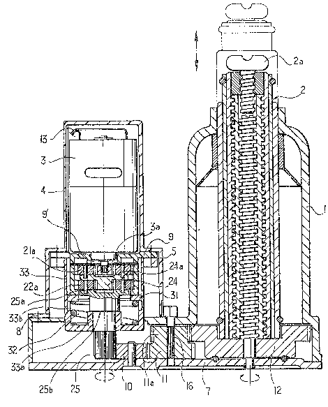
With reference now to the drawings, there is shown in
FIG.l an exploded-perspective view of a electrically operated
screw-type jack which includes a jack body l housing a
spiral lifting ram 2 therein, a housing 4 which contains a
reduction gears 20 and a servo motor 3 and a sa-Fety device 30
and is detachably mounted, by a plurality of bolts ~, to a
support integrally formed with the jack body 1~ and a support
base 7 which is fixedly mounted under the jack body 1 by a
plurality of rivets 6.
The reduction gears 20 are mounted in a sleeve 33 which
is an element of the sa-Fety dev i ce 30 and mounted to a
diaphragm 9 of the housing 4 by a plurality oF bolts 5. The
reduction gears 20 and the safety device 30 are important
elements in this screw-type jack.
As shown in FIG. 2 which is a cross-sectional elevational
view o-F this screw-type jack, the reduction gears 20 consist
of -First sun and planet gears 21, second sun and planet gears
22 and a sun gear cylinder 23.
As shown in FIG. 3 which is a fragmentary-exploded
perspective view showing the reduction gears 20 and the saFety
~3~
device 30, the first sun and planet gears 21 consists of a
plurality of First planetary gears 21a and a center gear 2~ on
which are Formed several pins 2~a For mountins the first
planetary gears 21a thereon. The -First planetary gears 21a
gear into a driving gear 3a of the servo motor 3 which
protrudes through a center opening 9' of the diaphragm 9.
Also, the second sun and planet gears 22 consist of a
plurality of second planetary gears 22a and a driYing pinion
25 on which are formed several pins 25a for mounting the
second planetary gears 22a thereon. The second planetary
gears 22a gear into the c,enter gear 24. The sun gear cylinder
23 consists of a cylinder of which top and bottom are open and
the inner surface 23' ts machined to function as a sun gear
which gears into the~First and second planetary gears 21a,22a.
At both diametrical sides of a lower end of the sun gear
cylinder 23 are formed a pair of fitting projections 23a which
arc to be ~Fitted with a hereinafter described clutch disk 31
of the safety device 30. Also, at both sides of the fitting
projections 23a are formed slants 23a'.
Referring again to FIG. 2, the sa-Fety device 30 consists
of a clutch disk 31, a clutch spring 32 and a sleeve 33 for
housing the clutch disk 31 and the clutch spring 32.
The clutch disk 31 is provided with a center opening, a
pair o-f fitting recesses 31a and a pair of fitting protrusions
31b. The -Fitting recesses 31a are fitted with the -fitting
2 ~ 3 ~ ~3
projeckions 23a, and provided with slants 31a' at both sides
thereof.
The clutch spring 32 functions to keep the fitting
projections 23a and the fitting recesses 31a in a fitting
state therebetween in case of a normal operation of the jack
or to make them break away from the fitting state in case of
an abnormal operation.
The sleeve 33 is consists of a cylindrical case in which
the reduction gears 20 and the safety device 30 are contained.
Also, at a center of a bottom of the sleeve 33 is formed a
cylindrical support 33a which can permit the driving pinion 25
of the reduction gears 20 to penetrat,e therethrough, and seat
a lower surface of the engaging flanged end 25b of the driving
pinion 25 on its top end (see FIGS. 4). Also, at both
diametrical portions inside the sleeve 33 are vertically
formed a pair oF guide grooves 33b for receiving the fitting
protrusions 31b of the clutch disk 31 in order to guide the
lifting movement of this jack. Furthermore around the top end
of ~he sleeve 33, there is provided with a plurality o, Fixing
holes 33c for mounting it to the diaphragm 9 by bolts 5 (see
FIG . 3 ) .
In addition, on the support base 7 are mounted a
transmitting gear 10 ~earing into the driving pinion 25, a
driven gear 11 gearing into the transmitting gear 10, and a
driven pinion 11a which is concentrically and integrally
3 ~
formed with the driven gear 11. The driven pinion lla gears
into a spur gear 12 fixed -to the lowermost oF the li-Fting ram
2, so that the lift-ing ram 2 can move upward or downward
depending on normal or reverse rotating direc-tion of the servo
motor 3.
Referring to FIG.5 which is a schematic wiring diagram
for this screw-type jack, the servo motor 3 is eleckrically
connected to a cigar-jack 14 of vehicle through a wiring 13
and a selector switch 15, so that the servo motor 3 can
operate in normal o.r reverse direction depending upon a normal
or reverse selection of the selector switch 15.
In lifting operation of this electrically operated screw-
type jack, when the jack is positioned under tne portion of
the vehicle to be lifted and the selector switch 15 is then
selected in lifting selection, the servo motor 3 can operate
in the normal direction in order to drive the driving gear 3a,
so that the first planetary gears 21a gearing into the driving
gear 3a are driven. At this time, the sun gear cylinder 23 of
which the gear machined inner surface 23 gears into the first
planetary gears 21a can not rotate because its fitting
projections 23a fit with the Fitting recesses 31a of the
clutch disk 31, also the fitting protrusions 31b of the disk
31 are received in the axial guide grooves 33b of the sleeve
33. Consequently, the rotation of the First planetary gears
21a results in rotation of the center gear 24 on which are
2~63~
mounted the gears 21a by the pins 24a, in turn rotation oF the
second planetary gears 22a which ~ear into the center gear 24.
ThereFore, the driving pinion 25 on which are mounted the
second planetary gears 25a by the pins 25a can rotate in
reduced speed. The rotation of the driving pinion 25 results
in the rotation of the transmitting gear 10 which gears into
the driving pinion 25, and then the rotation of the driven
gear 11 gearing into the transmitting gear 10, also the
rotation of -the driven pinion 11a which is concentrically and
integrally formed with the driven gear 11. Therefore, the
spur gear 12 gearing into the driven pinion lla rotates as a .. -
result of the rotation of the pinion lla, so that the lifting
ram 2 which is fixed to the spur gear 12 at its lower end
moves upward resulting in lifting the vehicle being loaded on
a saddle 2a of the lifting ram 2. Furthermore1 this screw- !
type jack can smoothly lift the vehicle to be lifted without
any trouble by providing the speed reduction by means of the
reduction gears 20.
On the other hand, in lowering operation of the jack, the
select switch l~ is in the lowering selection in order to
drive- the servo motor ~ in the reverse direction.
Cansequently, all of the driving gear ~a, the first and second
planetary gears 21a, 22a, driving pinion 2~, the transmitting
gear 10, the ciriven gear 11 and the driven pinion 11a
sequentially rotate in the reverse direction. Therefore, the
vehicle being loaded on ~he saddle 2a and liFted b~r the jack
can lo~ver as a result o-f the reverse rotations of the spur
gear 12 and the down~lard movement o^f the li-Fting rarn 2.
Also in a case that, in operating this jack, there is an
undesired overload on the jack, the sun gear cylinder 23 may
be in a racing because the driving power of the first and
second planetary gears 21a, 22a drives it to be forcedly
rotated, instead of being transmitted to the driving pinion 25
which is in overload, in order that it can be broken away from
the fitting state.with the clutch disk 31. Therefore, there
is an advantage that the servo motor ~ and the power
transmitting gear elements can be prevented from failure
though there is an undesired overload on the jack in lifting
operation.
When a lifting operation of the jack is abruptly stopped
resulting from a failure of the servo motor or the gear
elements, the square head pin 6 by which are mounted the
driven gear 11 and driven pinion lla on the support base 7 May
be rotated by a hand tool, such as a spanner, in order to
rotate the gear 11 and the pinion lla and the spur gear 12, so
that the lifting ram 2 can be lowered. Therefore, the
vehicle which are loaded on a jack having a trouble can be
safely unloaded by a simple hand treatment.
It should be noted that, even though there is a two step
reduction gears 20 comprising the first and second sun and
~3~
planet gears 21, 22, it is a nonlimiting embodiment for
description, consequently the s-teps of the reductior1gears may
be increased or reduced depending on a driving power of the
servo motor and a lifting speed of the lifting ram.
As described in -the above description, the electrically
operated screw-type jack in accordance with this inventior1 can
considerably promcte the driving power of the servo motor by
being provided with the reduction gears having the first and
second sun and planet gears and the sun gear cylinder, also
prevent its servo motor and power transmitting elements from
failures, when there is an undesired overload on it, by being
provided with the sun gear cylinder of the reduction gears and
the safety device, having clutch disk and the clutch spring,
in which the clutch disk may be out of the fitting s-tate with
the sun gear cylinder in overloading the jack in order that
the sun gear cylinder can be in a racing. Furthermore, there
is an advantage that the vehicle, being loaded on the jack
having a trouble, can be safely lowered by han~ operating the
square head pin by which the driven gear and the driven pinion
are mounted on the support base.
With the invention is thus explained, it is apparent that
various variations and modifications can be made without
departing from the scope of the invention. It is therefore
intended that the inven-tion be limited as indicated in the
appended claims.
1 1