Sélection de la langue

Search

Sommaire du brevet 2043824 

Énoncé de désistement de responsabilité concernant l'information provenant de tiers

Une partie des informations de ce site Web a été fournie par des sources externes. Le gouvernement du Canada n'assume aucune responsabilité concernant la précision, l'actualité ou la fiabilité des informations fournies par les sources externes. Les utilisateurs qui désirent employer cette information devraient consulter directement la source des informations. Le contenu fourni par les sources externes n'est pas assujetti aux exigences sur les langues officielles, la protection des renseignements personnels et l'accessibilité.

Disponibilité de l'Abrégé et des Revendications

L'apparition de différences dans le texte et l'image des Revendications et de l'Abrégé dépend du moment auquel le document est publié. Les textes des Revendications et de l'Abrégé sont affichés :

  • lorsque la demande peut être examinée par le public;
  • lorsque le brevet est émis (délivrance).
(12) Brevet: (11) CA 2043824
(54) Titre français: METHODE DE REALISATION DES DALLES DE FONDATION POUR UNE MACHINE A PAPIER AVANT L'INSTALLATION DE LADITE MACHINE
(54) Titre anglais: METHOD FOR MAKING THE FOUNDATION SLABS OF A PAPER MACHINE BEFORE THE INSTALLATION PROPER OF THE MACHINE
Statut: Périmé et au-delà du délai pour l’annulation
Données bibliographiques
(51) Classification internationale des brevets (CIB):
  • B28B 01/14 (2006.01)
  • B28B 23/00 (2006.01)
  • F16M 05/00 (2006.01)
(72) Inventeurs :
  • HAKALA, JAAKKO (Finlande)
  • SAVOLAINEN, EERO (Finlande)
(73) Titulaires :
  • VALMET PAPER MACHINERY INC.
(71) Demandeurs :
  • VALMET PAPER MACHINERY INC. (Finlande)
(74) Agent: MARKS & CLERK
(74) Co-agent:
(45) Délivré: 1996-01-09
(22) Date de dépôt: 1991-06-04
(41) Mise à la disponibilité du public: 1991-12-08
Requête d'examen: 1993-04-23
Licence disponible: S.O.
Cédé au domaine public: S.O.
(25) Langue des documents déposés: Anglais

Traité de coopération en matière de brevets (PCT): Non

(30) Données de priorité de la demande:
Numéro de la demande Pays / territoire Date
902838 (Finlande) 1990-06-07

Abrégés

Abrégé anglais


The invention concerns a method for making the foundation
slabs of a paper machine. In the method, reinforcement strands are
fitted inside a mold for a base beam. Before filling-concreting of
the mold, a base slab provided with a plurality of foundation
bolts is installed in connection with the reinforcement strands and
preferably on support of said strands. After the slab has been
installed as sufficiently planar manner with its face horizontal,
the filing-concreting of the base slab is carried out. Upon drying
of the concrete cast, the final tightening of the foundation bolts
of the base slab is carried out. The ultimate machining of the
base slab is carried out on site in the mill space by passing a
machining device supported by guides rails which have been adjusted
to a horizontal level along faces of the base slab.

Revendications

Note : Les revendications sont présentées dans la langue officielle dans laquelle elles ont été soumises.


The embodiments of the invention in which an exclusive
property or privilege is claimed are defined as follows:
1. A method for making the foundation slabs of a paper machine
comprising
fitting reinforcement strands inside a mold for a base beam,
installing a base slab having a plurality of foundation bolts
onto said reinforcement strands such that a face of said base slab
lies in a horizontal plane with an accuracy of about 5 mm of a
sufficiently desirable planar position, and thereafter
concreting said mold,
allowing the concrete cast to dry and then tightening said
foundation bolts to a final tightened position, and
carrying out the ultimate machining of said base slab by
passing a machining device support by guides which have been
adjusted to a horizontal level, along faces of said base slab.
2. The method of claim 1, further comprising carrying out said
ultimate machining of said base slab on site in a mill space, and
fixing said guides of said grinding device to the concrete
constructions of the building during the grinding process.
3. The method of claim 2, further comprising installing said
base slab after the filling-casting into said mold with a
requirement of accuracy of about 5 mm of the plane position, so
that said face of said base slab becomes substantially horizontal,
and the ultimate machining is carried out to an accuracy of about
0.15 mm of said plane position by means of machining carried out
on site by guiding a grinding and/or milling blade on said
horizontally installed guides and completing the threaded holes to
be made into said base slab by means of drilling units fitted on
said base slab.

4. The method of claim 1, wherein said concreting is carried
out by pouring concrete through filling-casting holes made in said
base slab.
5. The method of claim 1, wherein said concreting is carried
out by pouring concrete into a space between said base slab and a
wall of said mold.
6. The method of claim 3, further comprising guiding said
grinding device on said horizontally installed guides in a cycle of
longitudinal feeding, and thereafter displacing said grinding
device on transverse guide rails to a next cycle of longitudinal
feeding.

Description

Note : Les descriptions sont présentées dans la langue officielle dans laquelle elles ont été soumises.

2043824 91-255
- METHOD FOR MARING THE FOUNDATION 8LABS OF A PAPER
MA~UTN~ BEFORE THE INSTALLATION PROPER OF THE M~TN~
B~R~O~ND OF THE-l~.v~ lON
The invention concerns a method for making the foundation
slabs of a paper machine before the installation proper of the
machine.
A method for the making of the foundation of a paper machine
is known in the prior art. In this method, as a first step a
support beam is cast with reinforcement strands. Hole reservations
are then made in the support beam for bolts. The slab is installed
while the base bolts hang freely and fit into the reservations.
The bolts of the foundation slab are then fixed by concreting.
Below the foundation slab mounted on the reinforcement strands at
the top face of the base beam a so-called filling, i.e.
installation pieces, is fitted. After the desired correct plane
position of the foundation slab has been achieved in the
positioning of the slab, a so-called filling-concreting is carried
out between the slab and the base beam. Then the bolts in the slab
are tightened. Thus, before the filling-concreting, the slab must
be positioned very precisely to achieve a plane position.
The working step mentioned above is quite difficult, time-
consuming and, therefore, costly.
S~MMARY OF THE lNv~..lON
An object of the present invention is to provide an
improvement of the above method for installation and manufacture of
a base slab of a paper machine.
In view of above-mentioned object and others, the present
invention is related to method for making the foundation slabs of
a paper machine before the installation proper of the machine. The
base beam is formed by casting it on site into a mold.
Reinforcement strands are installed into the mold, onto which
X

2043824
strands the foundation slab is already mounted at this stage. The
foundation slab is mounted approximately in the correct location,
an accuracy of + 5 mm of the plane position being sufficient.
Thereafter, the concreting into the mold is carried out, and, after
the concrete has become dry, the bolts are tightened. In the final
stage, the ma~hining of the base slab is carried out on site by
rllnning the ma~hining device from one end of the slab to the other
along guide rails fixed to the foundation.
By means of the present invention, an accuracy of + 0.15 mm of
the plane position can be met, and the threaded holes can be
machined more accurately than by prior-art methods.
An important aspect of the method in accordance with the
present invention is that with regard to the concreting of the base
beam, reinforcement strands are fitted inside a mold and that
before filling-concreting of the mold, the base slab is installed
in connection with the reinforcement strands and preferably on
support of the reinforcement strands. Another important aspect of
the present invention is that after the slab has been installed as
sufficiently plane and with its face horizontal, the filling-
concreting of the base slab is carried out and upon drying of the
concrete cast, the bolts undergo their final tightening. In the
method of the present invention, the ultimate machining of the base
slab is carried out on site in the mill space by pressing a
ma~hining device on support of guides, which have been adjusted to
a horizontal level, along the slab faces.
BRIEF DE8CRIPTION OF THE DRA~ING8
The following drawings are illustrative of embodiments of the
invention and are not meant to limit the scope of the invention as
encompassed by the claims.
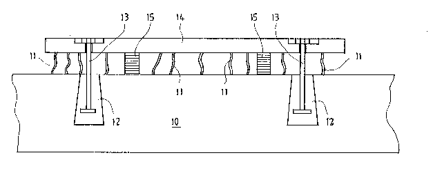
Figure 1 is a schematic illustration of a prior art method for
installation of the base slab based on filling.
X

2043824
~ - Figure 2 shows the location of two base slabs in relation to
one another. One of the base slabs is supported against the bottom
of the paper machine at one side of the paper machine, and the
other slab against the bottom of the paper machine, in the machine
direction, at the other side of the paper machine.
Figure 3 illustrates the method in accordance with the
invention, wherein, before the filling-concreting, the base slab is
supported on the mould and installed on the reinforcement strands
in a sufficiently accurate plane position.
Figure 4 is a schematic illustration of a so-called on-site
machining device, by whose means, on site in the factory space, the
base slab is fi n;shi ng-machine~ to bring it into a horizontal
plane.
DETAILED DESCRIPTION
Fig. 1 illustrates a prior art method for making of the
foundation. When the base beam 10 is being cast, reinforcement
strands 11 are fitted at the top face of the beam 10 and, in the
same connection, hole reservations 12 are made for the bolts 13.
After the casting of the concrete, the base slab 14 of steel with
- its hanging bolts 13 are placed on support of the reinforcement
strands 11. The slab 14 is fitted in an accurate horizontally
plane position by means of so-called filling, i.e. fitting pieces
15. After a suitable plane position has been achieved, so-called
filling-concreting is carried out between the top face of the beam
10 and the slab 14. In the final step the bolts 13 of the slab are
tightened.
Fig. 2 is an axonometric view of base slabs 14 installed on
base beams 10. In this Figure, dimensional quantities are
indicated to illustrate the relative positions and the dimensional
proportions of the slabs. L1 represents the distance between the
X

2043824
slabs, which is, e.g. from about 5 to about 12 m. The width L2 of
each slab is, e.g. from about 0.6 to about 0.7 m. The length ~ of
each line of slabs is, e.g. from about 30 to about 80 m, depen~ing
on the length of the paper machine. The thickness S of a slab is,
e.g. from about 60 to about 150 mm. The required accuracy of the
plane position is preferably about 0.25 mm.
In the prior art solutions, the machinings of the slab 14 were
carried out in workshops, and the holes in the slabs and the other
reservations employed in the fixing of a paper machine were also
made separately in workshops. The stage of installation itself
required high precision, because the slab was installed in its
ultimate position, determined by the requirement of plane position,
before the filling-casting. After-machining was not carried out.
In the present invention, the difficult working step has been
substantially avoided via the entirely novel method of installation
and manufacture of base slabs which has been provided.
As is shown in Fig. 3, the base beam 10, which is placed on
the beams P1, P2, is made by concreting it in the factory space on
site into the mold M. The reinforcement strands 11 are fitted into
the mold M, and the base slab 14 with its foundation bolts 13 is
fitted, with a requirement of accuracy of preferably about + 5mm of
plane position, onto the reinforcement strands 11. At this stage,
the filling-concreting is carried out immediately through the holes
14' in the slab 14. Upon drying of the concrete, the bolts 13 of
the slab 14 are tightened. The filling-casting holes 14' are not
needed n~cess~rily, because, as a rule, the slab is narrower than
the width of the concreting space, so that the filling-casting can
be carried out between the slab 14 and the mold M wall.
According to the invention, the ultimate machining of the base
slab is carried out as an on-site run of the factory hall by
bringing an on-site grinding device 20 into connection with the
base slabs 14 and by guiding the grinding device 20 on the guide

_ rails 21 along the slab faces. 2 0 4 3 8 2 4
Fig. 4 illustrates the ultimate gri n~ i ng of a base slab 14 in
accordance with the invention. The grinding device 20 is guided on
the guide rails 21, and after each cycle of longitudinal feeding
the device with its guide rails is displaced on the transverse
guide rails 22. The guide rails 21 and 22 are fixed to the
concrete base C, so that, by means of the device, sufficient feed
forces are achieved in the grinding situation. The guides 21, 22
are placed in the horizontal plane before grinding. Hereupon the
grinding or milling blade 23 of the device 20 is fed into the slab
base to be machines.
The examples provided above are not meant to be exclusive.
Many other variations of the present invention would be obvious to
those skilled in the art, and are contemplated to be within the
scope of the appended claims.
X

Dessin représentatif
Une figure unique qui représente un dessin illustrant l'invention.
États administratifs

2024-08-01 : Dans le cadre de la transition vers les Brevets de nouvelle génération (BNG), la base de données sur les brevets canadiens (BDBC) contient désormais un Historique d'événement plus détaillé, qui reproduit le Journal des événements de notre nouvelle solution interne.

Veuillez noter que les événements débutant par « Inactive : » se réfèrent à des événements qui ne sont plus utilisés dans notre nouvelle solution interne.

Pour une meilleure compréhension de l'état de la demande ou brevet qui figure sur cette page, la rubrique Mise en garde , et les descriptions de Brevet , Historique d'événement , Taxes périodiques et Historique des paiements devraient être consultées.

Historique d'événement

Description Date
Le délai pour l'annulation est expiré 2002-06-04
Lettre envoyée 2001-06-04
Accordé par délivrance 1996-01-09
Toutes les exigences pour l'examen - jugée conforme 1993-04-23
Exigences pour une requête d'examen - jugée conforme 1993-04-23
Demande publiée (accessible au public) 1991-12-08

Historique d'abandonnement

Il n'y a pas d'historique d'abandonnement

Historique des taxes

Type de taxes Anniversaire Échéance Date payée
TM (brevet, 6e anniv.) - générale 1997-06-04 1997-05-26
TM (brevet, 7e anniv.) - générale 1998-06-04 1998-05-21
TM (brevet, 8e anniv.) - générale 1999-06-04 1999-05-31
TM (brevet, 9e anniv.) - générale 2000-06-05 2000-05-30
Titulaires au dossier

Les titulaires actuels et antérieures au dossier sont affichés en ordre alphabétique.

Titulaires actuels au dossier
VALMET PAPER MACHINERY INC.
Titulaires antérieures au dossier
EERO SAVOLAINEN
JAAKKO HAKALA
Les propriétaires antérieurs qui ne figurent pas dans la liste des « Propriétaires au dossier » apparaîtront dans d'autres documents au dossier.
Documents

Pour visionner les fichiers sélectionnés, entrer le code reCAPTCHA :


Pour visualiser une image, cliquer sur un lien dans la colonne description du document (Temporairement non-disponible). Pour télécharger l'image (les images), cliquer l'une ou plusieurs cases à cocher dans la première colonne et ensuite cliquer sur le bouton "Télécharger sélection en format PDF (archive Zip)" ou le bouton "Télécharger sélection (en un fichier PDF fusionné)".

Liste des documents de brevet publiés et non publiés sur la BDBC .

Si vous avez des difficultés à accéder au contenu, veuillez communiquer avec le Centre de services à la clientèle au 1-866-997-1936, ou envoyer un courriel au Centre de service à la clientèle de l'OPIC.

({010=Tous les documents, 020=Au moment du dépôt, 030=Au moment de la mise à la disponibilité du public, 040=À la délivrance, 050=Examen, 060=Correspondance reçue, 070=Divers, 080=Correspondance envoyée, 090=Paiement})


Description du
Document 
Date
(aaaa-mm-jj) 
Nombre de pages   Taille de l'image (Ko) 
Abrégé 1994-02-18 1 24
Description 1994-02-18 5 187
Revendications 1994-02-18 2 53
Dessins 1994-02-18 3 55
Abrégé 1996-01-08 1 25
Revendications 1996-01-08 2 55
Description 1996-01-08 5 199
Dessins 1996-01-08 3 43
Dessin représentatif 1998-07-07 1 7
Avis concernant la taxe de maintien 2001-07-02 1 178
Taxes 1998-05-20 1 57
Taxes 1997-05-25 1 56
Taxes 1996-05-22 1 40
Taxes 1994-05-24 1 44
Taxes 1995-05-23 1 42
Taxes 1993-05-31 1 30
Correspondance reliée au PCT 1995-10-29 1 39
Courtoisie - Lettre du bureau 1993-05-16 1 55
Correspondance de la poursuite 1995-10-26 1 34
Correspondance de la poursuite 1993-04-22 1 28