Sélection de la langue

Search

Sommaire du brevet 2044015 

Énoncé de désistement de responsabilité concernant l'information provenant de tiers

Une partie des informations de ce site Web a été fournie par des sources externes. Le gouvernement du Canada n'assume aucune responsabilité concernant la précision, l'actualité ou la fiabilité des informations fournies par les sources externes. Les utilisateurs qui désirent employer cette information devraient consulter directement la source des informations. Le contenu fourni par les sources externes n'est pas assujetti aux exigences sur les langues officielles, la protection des renseignements personnels et l'accessibilité.

Disponibilité de l'Abrégé et des Revendications

L'apparition de différences dans le texte et l'image des Revendications et de l'Abrégé dépend du moment auquel le document est publié. Les textes des Revendications et de l'Abrégé sont affichés :

  • lorsque la demande peut être examinée par le public;
  • lorsque le brevet est émis (délivrance).
(12) Brevet: (11) CA 2044015
(54) Titre français: ETUI A MECANISME ROTATIF POUR SUBSTANCES EN BATON
(54) Titre anglais: A CASE WITH ROTARY MECHANISM FOR SUBSTANCES IN STICK FORM
Statut: Périmé et au-delà du délai pour l’annulation
Données bibliographiques
(51) Classification internationale des brevets (CIB):
  • A45D 40/06 (2006.01)
(72) Inventeurs :
  • SUSINI, CLAUDE (France)
  • MEJEAN, PASCAL (France)
(73) Titulaires :
  • REBOUL-SMT
(71) Demandeurs :
  • REBOUL-SMT (France)
(74) Agent: NORTON ROSE FULBRIGHT CANADA LLP/S.E.N.C.R.L., S.R.L.
(74) Co-agent:
(45) Délivré: 1999-06-15
(22) Date de dépôt: 1991-06-06
(41) Mise à la disponibilité du public: 1991-12-09
Requête d'examen: 1996-06-21
Licence disponible: S.O.
Cédé au domaine public: S.O.
(25) Langue des documents déposés: Anglais

Traité de coopération en matière de brevets (PCT): Non

(30) Données de priorité de la demande:
Numéro de la demande Pays / territoire Date
90 07 133 (France) 1990-06-08

Abrégés

Abrégé anglais


ABSTRACT OF THE DISCLOSURE
In a case equipped with a rotary mechanism for
substances in stick form, the danger of accidental
disengagement of the nipples of the sliding cup from the
guide sleeves at the end of travel of the nipples is
eliminated by inserting the edges of the walls of the
slots of the inner sleeve within channels formed in the
nipples.

Revendications

Note : Les revendications sont présentées dans la langue officielle dans laquelle elles ont été soumises.


-9-
The embodiments of the invention in which an exclusive
property or privilege is claimed are defined as follows:
1. A case for a substance in stick form and in
particular lipstick, having a stick-holder cup which is
capable of sliding axially within two mutually rotating
concentric coaxial sleeves made up of a stationary outer
sleeve and a rotary inner sleeve, there being cut in the
outer sleeve two internal helical grooves symmetrically
displaced by 180°, the rotary inner sleeve being
provided with two diametrically opposite and symmetrical
longitudinal slots, each slot being branched-off at 90°
into a recess at each end of travel of the cup, said
recess being oriented in the direction opposite to the
rotation of the sleeve which brings the cup to this end
of its travel, said cup being provided with two radial
nipples relatively displaced by 180°, each nipple being
passed respectively through a slot so as to penetrate
into a groove at the distal end thereof, wherein the
helical grooves have a width adapted to that of the
nipple heads and greater than the width of the recesses,
the nipples being provided with symmetrically-cut
channels located opposite to the inner sleeve and having
a Width adapted to the thickness of the inner sleeve and
a depth corresponding to a spacing which is adapted to
the width of the recesses, with the result that the
nipples slide readily with a small clearance within the
helical grooves, the slots and the recesses but grip

-10-
with slight friction the oppositely-facing edges of the
wall of the inner sleeve at least within the recesses.
2. A case according to claim 1, wherein the
longitudinal slots have the same width as the recesses
and the nipple channels are circular.
3. A case according to claim 1, wherein the
longitudinal slots have the same width as the helical
grooves and the nipple channels form notches parallel
to the orientation of the recesses.
4. A case according to claim 1, wherein the
outer edge of the wall of the inner sleeve is
chamfered at least at the bottom ends of the recesses.
5. A case according to claim 4, wherein the
recesses corresponding to the withdrawn position of the
stick within the case are reduced to a chamfered
external lateral edge of the end portion of each
longitudinal slot.
6. A case according to claim 1, wherein the
inner sleeve and the outer sleeve have complementary
stops for limiting the relative rotation between the
sleeves to less than one revolution and determining the
ends of travel of the cup.

Description

Note : Les descriptions sont présentées dans la langue officielle dans laquelle elles ont été soumises.

~401~
A CAS~ WITH ROTARY MECHANISM FOR
SUBSTANCES IN STICK FO~
BACKGROUND OF THE INVENTION
Field of the Invention
The present invention relates to the packaging
industry, more specifically for packaging sticks of
substances of the lipstick type in cases having a rotary
lifting mechanism which makes it possible to move the
stick out of the case at the time of use without
separating it from the case, then to withdraw it into
the case until the next time it is used.
Description of the Prior Art
A conventional case has a stick-holder cup
which is capable of sliding axially within two mutually
rotating concentric coaxial sleeves, namely a stationary
outer sleeve and a rotary inner sleeve. In the outer
sleeve are cut two internal helical grooves symmetrically
displaced by 180. The rotary inner sleeve has two
diametrically opposite and symmetrical ~ongitudinal
slots, each slot being branched-off at 90 into a
recess at each end of travel of the cup. The recess
is oriented in the direction opposite to the rstation
of the sleeve which brings the cup to this end of its
travel. The cup has two radial nipples relati~ely
displaced by 180 and each nipple passes respectively

0 1 ~
through a slot so as to penetrate into a groove at its
distal end.
For reasons of appearance and cost price, it
is standard practice to construct the mechanisms of
these cases from thin materials which usually consist of
plasticsO The mechanical strength of plastics proves
suitable for normal use but may sometimes ke insufficient
to prevent the nipples from escaping from the channels
~ and the slots when an excessive twist is exerted at the
end of travel of the cup. The accidental disengagement
thus produced has an adverse effect on the subsequent
operation of the mechanism. In order to overcome this
drawback, the wall thickness of the inner and outer
sleeves is increased to the maximum extent which is
compatible with a commercially acceptable diameter of
the case while endeavoring to find a compromise with
attractiveness of appearance and cost which cannot be
fully satisfactory.
The object of the invention is to overcome
this disadvantage of conventional cases and to prevent
accidental disengagement of the rotary mechanisms even
with thin-walled sleeves.
SUMMARY OF THE INVENTION
The invention relates to a case of the
aforementioned type for a substance in stick form, said
case being distinguished by the fact that the helical

~i3~4~
grooves have a width adapted to that of the nipple heads
and greater than the width of the recesses, the nipple~
being provided with symmetrically-cut channels located
opposite to the inner sleeve and having a width adapted
to the thickness of the inner sleeve and a depth
corresponding to a spacing which is adapted to the width
of the recesses, with the result that the nipples slide
readily with a small clearance within the helical
grooves, the slots and the recesses but grip with slight
10 friction ~he oppositely-facing edges of the wall of the
inner sleeve at least within the recesses.
The longitudinal slots can have the same width
as the recesses, in which case the nipple channels are
circular, or else the longitudinal slots can have the
same width as the helical grooves, in which case the
nipple channels form notches parallel to the orientation
of the recesses.
The outer edge of the wall of the inner sleeve
can be chamfered, at least at the bottom ends of the
recesses, in order to apply the nipples more effectively
against the internal face of said wall and to facilitate
entry of the nipples into the recesses. It is even
possible to reduce the recesses corresponding to the
withdrawn position of the stick within the case to a
chamfered external lateral edge of the end portion of
each longitudinal slot.

4~l~
--Ds~
It is also possible to prevent accidental
disengagement with even greater effectiveness by
providing the inner sleeve and the outer sleeve with
complementary stops for limitillg the relative rotation
between the sleeves to less than one revolution and
positively determining the ends of travel of the cup.
A more complete understanding of the invention
will be gained from the following detailed description
- and from the accompanying drawings in which a few
embodiments have been selected solely by way of example
from the many forms of execution, adaptations and
variants of the invention within the capacity of those
versed in the art.
BRIEF DESCRIPTION OF THE DRAWINGS
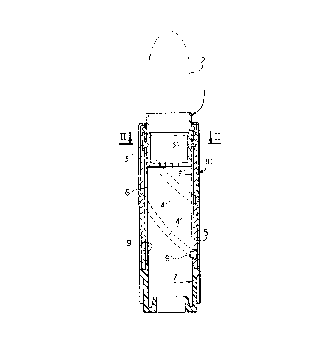
FIG. 1 is a schematic view in elevation and in
axial cross-section showing a case in accordance with
the invention.
FIG. 2 is a schematic view in diametral
cross-section to a larger scale, this view being taken
along line II-II of FIG. 1.
FIG. 3 is a schematic view in perspective
showing the cup of the case of FIGS. 1 and 2.
FIG. 4 is a schematic detail view in
perspective and to a larger scale showing a nipple of
25 the cup of the case of FIGS. 1 to 3.
FIG. 5 is a schematic view in elevation and in

axial cross-section showing a chamfered longitudinal
slot of a case sleeve in accordance with the invention.
FIG. 6 is a schematic front view of the slot
of FIG. 5.
FIG. 7 is a view which is similar to FIG. 4
and shows an alternative embodiment.
FIG. 8 is a schematic front view in elevation
illustrating a sleeve with longitudinal slots and
showing the end-of-travel positions of the nipples of
the cup of FIG. 7.
FIG. 9 iS a schematic view in cross-section
along line IX-IX of FIG. 8.
EIG. 10 is a schematic view in perspective
showing a sleeve with helical grooves and a rotation-
limiting stop for a case in accordance with the
invention.
FIG. 11 is a schematic view in perspective
showing a sleeve with longitudinal slots and a stop for
complementary limitation of rotation of the sleeve of
FIG. 10.
DESCRIPTION OF THE PREFERRED EMBODIMENTS
In these figures, corresponding elements are
designated by the same reference numerals to which an
index may be assigned. For the sake of enhanced clarity
of the drawings, the respective dimensions and
proportions of these elements may not be complied with.

4 0 ~ ~
The case for a substance in the form of a stick
such as lipstick as illustrated in FIGS. 1 to 4
essentially includes a cup 1 for holding a stick 2.
Said cup 1 has two diametrically opposite radial nipples
3, 3', the distal ends of which slide within
symmetrically opposite helical grooves 4, 4' cut in the
internal face of an outer sleeve 5 after having passed
through longitudinal slots 6, 6' of an inner sleeve 7
- which is concentric with the outer sleeve 5 and in
mutually rotating relation therewith. At each end of
travel of the cup 1, each slot 6, 6' branches-off at 90
into a recess 8, 8', 9, 9' which is oriented in the
direction opposite to the rotation of the inner sleeve
7 so as to bring the cup 1 to this end of its travel.
An external sheath 10 which may be decorative if so
desired is fitted around the outer sleeve 5.
The heads 11, 11' of the nipples 3, 3' are
slightly smaller in width than the helical grooves 4, 4'
in which they slide freely but are of greater width
than the recesses 8, 8', 9, 9'. Channels 12, 12' are
cut symmetrically in said nipples 3, 3' opposite to the
wall of the inner sleeve 7. These channels have a width
which is slightly greater than the thickness of the
inner sleeve 7 and a depth which is slightly smaller
than the width of the recesses 8, 8', 9, 9'.
Thus the nipples 3, 3' are capable of sliding

~i31~4~
freely with a small clearance within the grooves 4, 4'
through the slots 6, 6 ' and the recesses 8, 8 ', 9, 9 '
while gripping with slight friction the oppositely-facing
edges of the inner sleeve 7 within the recesses at each
end of travel of the cUp 1, thuS guarding against any
danger of accidental disengagement caused by escape of
the nipples from the recesses.
In order to ensure good insertion of the
channels 12, 12' within the recesses 8, 8', 9, 9', the
outer edges of the sleeve wall can be chamfered as
indicated at 13, 13', 14 in FIGS. 2, 5 and 6.
In an alternative embodiment shown in the
lower portion of FIG. 6, the recess is reduced to a
chamfered edge 14a of the end portion of the slot 6a
which permits gripping of the wall of the sleeve 7a
within the channel of the nipple 3a with immobilization
of the cup at the bottom end of travel. In this
position, the cup together with its stick are withdrawn
within the case and are not subjected to any stress as
at the time of frictional application of the stick
against a surface when the stick is extended outwards
from the case at the other end of travel of the cup.
In this other position, the slot should preferably be
provided with an extension in the form of a lateral
recess having a length at least equal to the diameter
o~ the nipple 3 in order to ensure good axial locking

~ J i~
o f the cup .
FIGS. 7 and 8 illustrate another alternative
embodiment of the invention in which the channels of the
nipple 3b are formed by two notches 12b, 12b' which are
parallel to the axis of the recesses 8b, 8b'. The
clearance between the bottom faces of the notches of a
nipple is slightly smaller than the width of the recesses
into which the nipples penetrate.
- In order to ensure more positive rotational
locking at each end of travel of the cup, a stop lug 15
can advantageously be provided at one end of the sleeve
5c having helical grooves. Said stop lug is adapted to
cooperate with another stop lug 16 on the corresponding
end of the sleeve 7c having longitudinal slots, as shown
in FIGS. 10 and 11. The width of said lugs 15, 16
limits the relative rotation of the sleeves 5c and 7c
to a little less than one revolution, which is not
objectionable ~or a practical design of lipstick case.

Dessin représentatif
Une figure unique qui représente un dessin illustrant l'invention.
États administratifs

2024-08-01 : Dans le cadre de la transition vers les Brevets de nouvelle génération (BNG), la base de données sur les brevets canadiens (BDBC) contient désormais un Historique d'événement plus détaillé, qui reproduit le Journal des événements de notre nouvelle solution interne.

Veuillez noter que les événements débutant par « Inactive : » se réfèrent à des événements qui ne sont plus utilisés dans notre nouvelle solution interne.

Pour une meilleure compréhension de l'état de la demande ou brevet qui figure sur cette page, la rubrique Mise en garde , et les descriptions de Brevet , Historique d'événement , Taxes périodiques et Historique des paiements devraient être consultées.

Historique d'événement

Description Date
Le délai pour l'annulation est expiré 2007-06-06
Lettre envoyée 2006-06-06
Inactive : Page couverture publiée 1999-06-16
Accordé par délivrance 1999-06-15
Inactive : Taxe finale reçue 1999-03-08
Préoctroi 1999-03-08
Un avis d'acceptation est envoyé 1998-10-26
Lettre envoyée 1998-10-26
Inactive : Approuvée aux fins d'acceptation (AFA) 1998-10-01
Inactive : Renseign. sur l'état - Complets dès date d'ent. journ. 1998-01-28
Inactive : Dem. traitée sur TS dès date d'ent. journal 1998-01-28
Exigences pour une requête d'examen - jugée conforme 1996-06-21
Toutes les exigences pour l'examen - jugée conforme 1996-06-21
Demande publiée (accessible au public) 1991-12-09

Historique d'abandonnement

Il n'y a pas d'historique d'abandonnement

Taxes périodiques

Le dernier paiement a été reçu le 1999-05-12

Avis : Si le paiement en totalité n'a pas été reçu au plus tard à la date indiquée, une taxe supplémentaire peut être imposée, soit une des taxes suivantes :

  • taxe de rétablissement ;
  • taxe pour paiement en souffrance ; ou
  • taxe additionnelle pour le renversement d'une péremption réputée.

Les taxes sur les brevets sont ajustées au 1er janvier de chaque année. Les montants ci-dessus sont les montants actuels s'ils sont reçus au plus tard le 31 décembre de l'année en cours.
Veuillez vous référer à la page web des taxes sur les brevets de l'OPIC pour voir tous les montants actuels des taxes.

Historique des taxes

Type de taxes Anniversaire Échéance Date payée
Requête d'examen - générale 1996-06-21
TM (demande, 6e anniv.) - générale 06 1997-06-06 1997-05-27
TM (demande, 7e anniv.) - générale 07 1998-06-08 1998-05-20
Taxe finale - générale 1999-03-08
TM (demande, 8e anniv.) - générale 08 1999-06-07 1999-05-12
TM (brevet, 9e anniv.) - générale 2000-06-06 2000-04-17
TM (brevet, 10e anniv.) - générale 2001-06-06 2001-05-24
TM (brevet, 11e anniv.) - générale 2002-06-06 2002-05-16
TM (brevet, 12e anniv.) - générale 2003-06-06 2003-06-04
TM (brevet, 13e anniv.) - générale 2004-06-07 2004-05-17
TM (brevet, 14e anniv.) - générale 2005-06-06 2005-05-27
Titulaires au dossier

Les titulaires actuels et antérieures au dossier sont affichés en ordre alphabétique.

Titulaires actuels au dossier
REBOUL-SMT
Titulaires antérieures au dossier
CLAUDE SUSINI
PASCAL MEJEAN
Les propriétaires antérieurs qui ne figurent pas dans la liste des « Propriétaires au dossier » apparaîtront dans d'autres documents au dossier.
Documents

Pour visionner les fichiers sélectionnés, entrer le code reCAPTCHA :


Pour visualiser une image, cliquer sur un lien dans la colonne description du document. Pour télécharger l'image (les images), cliquer l'une ou plusieurs cases à cocher dans la première colonne et ensuite cliquer sur le bouton "Télécharger sélection en format PDF (archive Zip)" ou le bouton "Télécharger sélection (en un fichier PDF fusionné)".

Liste des documents de brevet publiés et non publiés sur la BDBC .

Si vous avez des difficultés à accéder au contenu, veuillez communiquer avec le Centre de services à la clientèle au 1-866-997-1936, ou envoyer un courriel au Centre de service à la clientèle de l'OPIC.


Description du
Document 
Date
(aaaa-mm-jj) 
Nombre de pages   Taille de l'image (Ko) 
Revendications 1993-11-05 2 54
Abrégé 1993-11-05 1 9
Dessins 1993-11-05 2 55
Description 1993-11-05 8 204
Dessin représentatif 1999-06-07 1 6
Avis du commissaire - Demande jugée acceptable 1998-10-25 1 164
Avis concernant la taxe de maintien 2006-07-31 1 173
Correspondance 1999-03-07 1 53
Taxes 1996-05-27 1 52
Taxes 1995-05-30 1 56
Taxes 1994-06-02 1 57
Taxes 1993-05-19 1 41