Note : Les descriptions sont présentées dans la langue officielle dans laquelle elles ont été soumises.
2~4 4~4~
-
EI,ECTRIC HORN ~ITH SOLID STATE DRIVER
FIELD OF THE lNv~ih~IoN
This invention relates to an electric horn with
a solid state driver and particularly to such a horn
with coupling at resonant frequency between the
electrical and the mechanical systems.
BACRGRO~JND OF THE lNV~lION
Electric horns as commonly used on automotive
vehicles have traditionally used a vibrating
diaphragm driven by an electromagnetic device.
Current pulses are developed by a mechanical switch
responsive to diaphragm movement such that the
switch, being normally closed, would energize a
magnetic coil to cause diaphragm movement in one
direction against its spring bias and the movement
would open the switch allowing the diaphragm return
in the other direction thus closing the switch and
causing the cycle to repeat. The life of such horns
is limited by the life of the mechanical switch used
in the horn. It is therefore desirable to devise an
alternative to the mechanical switch, however
requirements of high power, immunity to high voltage
spikes caused by switching an inductive load, and
mechanical ruggedness places severe limits on the
technology that may be successfully employed.
It has been proposed in the U. S. Patent to
Haigh 3,846,792 to use an electronic driver to supply
short current pulses to an electric sound-producing
.*
20~4248
P-358 ~ - 2 -
device. In that driver an oscillator is used to
provide a series of pulses to an electromagnet which
attracts a ferromagnetic diaphragm. The pulses have
a repetition rate substantially less than the natural
frequency (3000 Hz) of the diaphragm. For each
pulse, the electromagnet attracts and then releases
the diaphragm to allow it to vibrate through a number
of cycles before applying another pulse. A feedback
circuit responsive to diaphragm position slaves the
pulse timing to the diaphragm frequency to assure
efficient coupling. This arrangement is adapted to
high frequency horns which have small diaphragm
movement and readily continue to vibrate when input
pulses are removed, and does not apply to low
frequency (400-500 Hz) horns. The diaphragms of the
low frequency horns do not sustain ringing long after
the input pulse is removed. Moreover, the feedback
circuit of Haigh is ineffective to accurately time
the pulse to the diaphragm movement at low frequency.
To obtain efficiency of operation of a horn, it
is necessary to couple the electrical energy into the
mechanical part of the system in a manner which makes
best use of that energy already imparted to the
diaphragm assembly. In the case of a low frequency
horn, the synchronism of input pulses and diaphraqm
movement is of paramount importance in obtaining the
highest sound energy output for a given electrical
power input. The prior proposal does not provide a
solution to attaining that end.
2044248
-- 3
SUMMARY OF THE lNv~N-llON
Accordingly the present invention seeks to provide a horn with
an electronic driver for inputting energy into the horn in each
cycle in timed relation with the natural movement of the horn
diaphragm.
The invention broadly pertains to a vehicle horn for an
automotive vehicle having a vehicle battery with a voltage rating
of twelve volts or greater, the horn comprising a closed housing
having a diaphragm mounted on the housing with its periphery
clamped thereto and forming a substantially closed chamber, a
driving coil mounted within the chamber and a ferromagnetic plunger
coupled to the center of the diaphragm and extending into the coil
for imparting motion to the diaphragm upon energizations. The
diaphragm suspends the plunger for reciprocating motion relative to
the coil and has a spring characteristic whereby the coupled
diaphragm and plunger have a resonant frequency of mechanical
vibration of about four hundred hertz and a solid state drive
circuit is coupled between the battery and the coil for energizing
the coil.
In one aspect the driver circuit generates a DC pulse train,
adjusting means independent of the actual vibration frequency of
the diaphragm for presetting the driver circuit to a pulse
repetition rate substantially equal to the resonant frequency and
has a duty cycle of sixty percent or greater whereby the diaphragm
vibrates at substantially the resonant frequency and generates
sound waves at substantially the resonant frequency.
In another aspect, the invention provides a solid state driver
circuit mounted externally of the chamber and coupled between the
battery and the coil for energizing the coil, the driver circuit
generating a DC pulse train, adjusting means independent of the
actual vibration frequency of the diaphragm for presetting the
driver circuit to a pulse repetition rate substantially equal to
the resonant frequency whereby the diaphragm vibrates at
substantially the resonant frequency and generates sound waves at
substantially the resonant frequency.
_ 4 _ 2044248
In still another aspect the driver circuit includes a timer
for generating a DC pulse train having a duty cycle of sixty
percent or greater, the timer including an adjustable resistor for
adjusting the pulse repetition rate of the pulse train independent
of the actual vibration frequency of the diaphragm, the resistor
being adjustable during manufacture of the horn and having an
adjusted value which sets the pulse repetition rate substantially
equal to the resonant frequency.
DESCRIPTION OF THE DRAWINGS
The above and other advantages of the invention will become
more apparent from the following description taken in conjunction
with the accompanying drawings wherein like references refer to
like parts and wherein:
FIGURE 1 is a cross-section view of an electric horn according
to the invention, and
FIGURE 2 is a schematic diagram of a solid state horn driver
circuit according to the invention.
BEST MODE FOR CARRYING OUT THE INVENTION
Referring to FIGURE 1, an electric horn has a sheet metal
housing 10 secured to a plastic projector 12. A spring steel
diaphragm 14 is trapped at its margins between the housing 10 and
projector 12 and is attached at its center to a ferromagnetic
plunger 16. An aperture 18 in an end wall 20 of the housing 10
holds a pole piece 22 which extends toward the plunger 16. An end
face 24 of the pole piece 22 iS spaced from an end face 26 of the
plunger 16 by a small gap. The opposite end 25 of the pole piece
22 is threaded to receive a mounting bracket 27 and a securing nut
29.
The housing 10 is stepped to define a small end portion
28 including the end wall 20 and a larger portion 30 terminating in
a radial flange 3 2 for supporting the diaphragm. An intermediate
generally planar annular portion 34 interconnects the small end
portion 28 and the larger portion 30. An electromagnetic coil 36
fits within the small end portion 28 and surrounds adjacent ends of
. 2044248
-- 5
the plunger 16 and pole piece 22. An annular mounting plate 37
secured to the intermediate portion 34 by rivets 38 retains the
coil in the end portion 28. The plate 37 iS apertured to
accommodate the plunger 16 for free movement therein.
Regarding the mounting of the diaphragm, annular gaskets 40
conforming to the diaphragm margin are seated on either side of the
diaphragm. The projector presses the gaskets 40 and diaphragm 14
against the flange 32 and fasteners 42 secure the assembly. The
plunger 16 has a stem 44 of small diameter protruding through the
diaphragm at its center and through a washer 46 on each side of the
diaphragm. The stem defines a shoulder 48 on the plunger to engage
one washer and the end of the stem 44 is upset to engage the other
washer 46, thereby securing the diaph,ragm and the plunger for
movement as a unit. The combined mass of the diaphragm 14 and the
plunger 16 along with the spring rate of the diaphragm determine
the resonant frequency of the diaphragm assembly. The resultant
sound is amplified by the projector 12 which is tuned to the
resonant frequency of the plunger/diaphragm assembly.
The mechanical aspect of the horn is described
in further detail in U.S. Patent 4,361,952 issued
to James Neese, which may be referred to for
further details. The chief difference between that patent
and the present disclosure is the arrangement for
applying electrical pulses to the coil for driving
the diaphragm at its resonant frequency. In patent 4,361,952,
mechanical contacts within the horn housing operated
by movement of the plunger open and
2i~4~24~
.
P-3S8 , - 6 -
close the circuit to the coil. In this invention, a
solid state switching circuit supplies the pulsed
current to the coil.
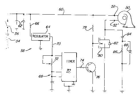
S Referring to FIGURE 2, the horn 50 has
terminals 52, 52' connected to the coil. A battery
or other power source 54 is coupled to the horn
terminals 52, 52' through a switch 56 and a driver
circuit 58. The switch 56, when closed, connects the
battery 54 to the positive line 60 which directly
couples to one of the horn terminals 52. The other
terminal 52' is intermittently connected to ground
through the driver circuit 58.
The driver circuit 58 has a pair of capacitors
62 between the line 60 and ground to suppress EMI and
RFI transient spikes. A voltage regulator 64 coupled
to the line 60 through a current limiting resistor 66
supplies suitable voltage to an oscillator circuit 68
which employs a 555 timer 70. The timer has several
terminals connected in a well known oscillator
configuration to the regulator 64 and to ground
through various resistors and capacitors. In
particular, an adjustable resistor 72 is used to
adjust the timer output frequency as well as the duty
cycle. The values of a fixed resistor 73 and the
adjustable resistor 72 are selected to determine the
basic frequency and the duty cycle with some fine
adjustment allowed by resistor 72. The output of the
oscillator circuit 68 is coupled through a resistor
74 to the base of a transistor 76 serving as the
first stage of a power driver. The transistor 76
emitter is connected to ground and the collector is
- 20~42~8
P-358 , _ 7 _
connected through a current limiting resistor 78 to
the positive line 60. The emitter is also connected
to the gate of a power MOSFET 80 which serves as the
driver output stage. An internal diode 8 2 across the
source and drain of the MOSFET 80 offers transient
protection. In addition, a capacitor 84 and a
snubber circuit in series with the capacitor 84
comprising a resistor 86 in parallel with a diode 88
suppress a transient spike generated as the horn coil
lo initially charges up. The source of the MOSFET 80 is
connected to the horn terminal 52' to allow pulsed
current flow through the coil 36 when the driver
circuit 58 switches on.
The driver circuit as described above is
tailored for use with a 12 volt horn having a
frequency of about 400 Hz but applies to high
frequency horns as well. To obtain optimum
efficiency in horn operation (i.e., the highest sound
level output for a given current input) the driver
frequency should, within narrow limits, match the
resonant frequency of the diaphragm assembly. The
frequency of the driver circuit 58 is precisely
adjusted to the desired horn frequency during
manufacture by adjustment of the timer resistor 72
which may be a laser trimmed or otherwise adjustable
resistor. The diaphragm will be driven at that rate.
Small resonant frequency differences between the
mechanical and electrical systems are tolerated at
the expense of some reduction of sound level.
Voltages higher than 12 volts require small
modifications in the driver circuit. For horns rated
20~42~8
P-358 , - 8 -
.
for use at 24, 36, or 48 volts a Darlington pair is
used in place of the power MOSFET 80. A different
value for the timing resistor 72 is used for each
voltage rating to adjust the duty cycle of the
S current pulse to the coil. While it is preferred to
operate the 12 volt horns with a 60% duty cycle
current, the duty cycle is progressively greater for
higher voltages, approaching 90~ at 48 volts. The 36
and 48 volt horns require an extra voltage regulator
between the resistor 66 and the regulator 64. With
the extra regulator, a power source 54 up to 125
volts may be used. The regulators prevent variations
in timer frequency as a result of power supply
voltage variations.
In operation, upon closing of the switch 56,
the timer 70 will issue a train of pulses at the
resonance frequency of the diaphragm 14 activating
the first and second stages 76 and 80 of the driver
circuit 58 to send a train of power pulses at the
same frequency to the coil 36. The resulting
magnetic impulse causes the plunger 16 and diaphragm
14 to move synchronously with the power pulses so
that energy is added to the diaphragm system in the
most harmonious and efficient manner. Even if the
power pulses were just slightly off the peak of the
resonance adequate coupling can be accomplished. In
the 12 volt system a tolerance of + or - 10 Hz is
permitted, the sound output being reduced by 3 or 4
decibels. In the 24 to 48 volt systems the tolerance
is + or - 25 Hz since the more powerful pulse input
can overcome the phase disparity between the
electrical and the mechanical system.
- 20~1248
P-358 , - 9 -
The basic driver circuit 58, with the
exceptions noted above is useful for horns of each
voltage rating. The circuit provides a square wave
output to the coil which is especially desirable
since positive horn actuation is accomplished
consistently at the initiation of each current pulse
whereas sine wave or saw tooth waves increase
gradually and are effective for coil energization
only when they overcome transients in the coil
resulting from the previous cycle. The resulting
predictable response allows a particular sound
quality to be produced consistently for each horn
design.
lS It will thus be seen that the present invention
provides a horn switching arrangement yielding longer
horn life, precise calibration, universal application
to various horn models, and precise switching for
improved quality sound. The invention applies to
high and low horn frequencies and allows maximum
sound output by energizing the coil in each cycle for
a time determined by adjusting the duty cycle.
Although the invention is described herein as applied
to a projector type horn, it is also useful with a
resonator type horn.