Note : Les descriptions sont présentées dans la langue officielle dans laquelle elles ont été soumises.
2~ 2~
EMBOSSED COVER FOR RING BINDER MEC~I~NISM
Back~round Of The Invention
~ hile ring binder mechanisms have used cover
a~nbosses for locking purpose~ (U.S. Patents Nos. 4,813,803
5and 3,~4,~86) and designers have varied the shape of ring
halves for sheet control purposes, no fully satisfactory
sheet control mechanism has yet been proposed.
Broadly, the present invention comprises platform
a~nbossas ormed in the arcuate cover of a ring binder
mach~nis1n which embosses are located and shaped to lift and
~1.ida paper in the binder.
It is a feature that the paper in the ring binder
is acted upon by the emboss platforms to support the paper,
thus reducing and eliminating sheets of paper from becoming -
"bound" (or held) between the ring halves and the ring
binder arcuate cover.
ria~ Description Of The Drawinqs
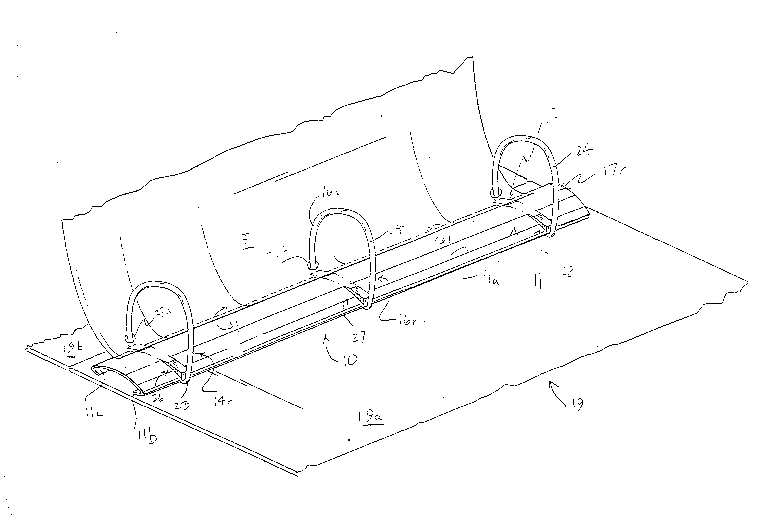
Fig. l is a perspective view of the ring
machanism attached to a binder cover;
~5 Fig. 2 is an enlarged sectional view along line
~-2 of Fig. 2 showing the curved cover plate during
~abrication;
Fig. 3 is a partial plan view of the ring
machanism including cover plate during fabrication; and
Fig. 4 is an end view of the assembled mechanism
and binder.
Description Of The Preferred Embodiment
In the Figures, ring mechanism 10 includes curved
arcuate convex cover 11 including upper convex surface lla
and bendable legs llb, llc; toggle plates 12, 13 and ring
halves 14, 16 and 17 each of which carry a designation (r)
5for right or (l) for left. The mechanism 10 is attached to
binder outside cover 19 by rivets 21. Cover surface lla is
generally uniform through its length except for platform
areas to be described hereafter. Cover 19 includes portions
l9a, 19b and l9c hinged together.
Each ring half 14, 16 and 17 ( (r) right and (l)
left) is engaged to a toggle plate 12, 13. Each ring half
consists of a portion 22 engaged at one end to a plate 12,
13 and extending outwardly~ an elbow portion 23 and the
remaining half ring being arcuate portion ~. Arcuate
portion 24 is shaped to be positioned adjacent and close to
platform surface 33 as further shown herein.
Positioned between each pair of ring halves 14,
216, 17 are pairs of spaced-apart raised platforms 26, 27 and
28 of cover 11. Each such raised platform is designated (r)
for right or (l) for left. Each platform 26, 27, 28
includes a top surface 31 including substantially horizontal
surface 31a and slanted surface 311~, two (2) vertical sides
2532a, 32b and a vertical end 33. If desired surEaces 31a and
31b may be in the same plane at a slight angle to the
horizontal. Platform ends 33 are slightly inboard of outer
cover lip 34 edge (Fig. 2). Preferably platforms 26, 27,
and 28 may be formed by embossing the cover surface lla but
other manufacture techniques are also contemplated.
Turning to Figs. 2 and 3, cover plate 11 is shown
during manufacture with raised platform 27 formed therein
2~ 2~$
but without legs llb, llc bent to final positions to
accommodate plates 12, 13.
With respect to Figs. 1 and 4, sheet of paper 37
with punch holes 38a-c has border edge 41 adjacent holes
538a-c which border edge 41 rests on platforms 26, 27 and 28
to prevent such border edge 41 from becoming engaged between
cover surface lla, top surface 31 and an arcuate portion 24
of ring halves 14, 16 and 17. There is a small gap G
between surface 31b and arcuate ring portion 24.
Paper sheet 37a is illustratively suppor.ted on
platform pair 28, as the sheet 37a is caused to be moved
upwardly toward the binder closed position (Fig. 4~. Sheets
are moved to a binder closed position by moving the cover
15portion 19a or l9c or otherwise.
