Note : Les descriptions sont présentées dans la langue officielle dans laquelle elles ont été soumises.
~607:'
DENTAL FLOSS THREA~ING-~EVIC~
Backqxoun~ of ~ LrYaL~1QL
The present invention relatQ8 to the dental floss
threader arts, including a novel and improved dental floss
threader, a method ~or making such a dental floss threader
and methods o~ dental ~lossing using such a dental floss
threader.
~ental ~loss is highly recommended and widely used
in oral hygiene ~or cleaning areas and surfaces between
abutting dental structures such as teeth, prosthetics and
orthodontic devices. When used between teeth, dental floss
18 typically wor~ed downwardly from a top surfacQ of the
teeth toward the gum line between abutting or ad~acent
surfaces. Once the ~loss i8 inserted between adjacent or
abutting teeth, it is worked back and forth along each
surface to remove undesirable particles and substances.
Whlle it i8 generally uncomplicated to floss
between teeth where at least a nominal space is available to
insert a piece o~ floss, it is very difficult to insert floss
between teeth which are tightly abutting or between
2 ~ 7 ~
prosthodontics such ~8 arti~icial teeth or bridge work.
Further, it is essentially impossible to insert a single
thread of ~loss underneath such prosthodontic devices without
the aid of a threading device.
Attempts to provide threading devices to insert
floss between tight spaces or under prosthodontic devices
have generally produced needle-like~devices through which
floss is threaded. These needle-like devices are inserted
through any available gap between or near the structures to
be flossed and then completely pulled through the gap in
order to feed the ~loss through.
While typical prior art devices arguably provide a
method o~ threading dental ~1088, they are often difficult to
use and tend not to achieve their purpose. Many prior art
floss threaders require regimens and if the regimen requires
effort on the part o~ the user the user tends to not follow
the regimen ultimately rQsulting in the failure of the
device. For example, a device for inserting dental floss
through interproximal areas is shown in U.S. Patent No.
3,g29,144 to Tarrson et al. and U.S. Patent No. 4,011,658 to
Tarrson et al. The dsvice shown in the Tarrson et al.
patents is essentially a needle having an enlarged loop at
the end thereo~. Dental floss must be inserted into the loop
by the user prior to threading the floss into interproximal
areas. This type o~ device thus requires additional effort
and preparation on the part o~ the user and therefore tends
to di courage use of the device as frequently as may be
desirable.
Further, a device as shown in the Tarrson et al.
patents requires that ths user keep on hand both a supply of
needle-like rlo8~ threading devices as well as ~loss. As an
additional matter, some areas may be too small or con~ined to
permit insertion o~ the needle-like device and the large
loop. Such small area3 may, there~ore, be neglected when
flossing, leading to potential oral hygiene complications.
-2-
2 0 ~ 6 0 7 ~
Other attempts to resolve the problems of flossing
as noted above are not believed to have succeeded. For
example, one prior art solution was to coat the tip of
predetermined lengths of ~loss with a material to make the
tip rigid. This was beliQvQd to permit insertion of the
~loss itself in a neQdle-like manner betwaen dental
structures including very sm~ll spaces. However, due to the
nature of dental flo3~, it i8 difficult to provide a
sufficiently stiff coa~ing to structurally support direct
insertion between den~al structures.
Obiec~s and Sum~Y o~ the Invention
It is an ob~ect of the present invention to provide
a floss threading device which permits insertion of dental
floss between dental structures.
A related ob~ect i8 to provide a dental floss
threader which ha~ a rigid structure which permits insertion
of dental flos~ into ~aps between dental structures.
Yet another ob~ect of the present invention is to
provide a novel method of threading floss between dental
structures.
Still another ob~ect of the present invention is to
provide a method of forming a ~loss threader having a charge
of floss retained in a tube which is formed with a reduced
diameter portion insertable between dental structures.
Briefly, and in accordance with the foregoing, the
present invention comprises a device, a method of use and a
method for making such a device, for threading floss between
dental structures. The device i8 formed of a tube including
a handle portion and a reduced diameter portion. A charge of
dental f 1088 iS retalned in the tube of which a lead portion
20~60 7~
extends through a tip aperturQ ~ormed at a terminal end or
tip of the reduced diameter portion. The lead portion is
coated with a material to sti~fen the same to further
facilitate insertion of the device between dental structures.
The device i8 formed by providing a tube and inserting a
charge oP f10B8 thereln. The tube and ~108~ have di~erent
melting points such that the melting point for the floss is
greater than the melting point for ~he tube material. The
tube is heated to approximately the melting point of the tube
material whereupon a portion of the tube is formed into the
reduced diameter portion. During the forming process, the
lead portion of the floss is retained in place such that upon
completion, it extends thxough the tip aperture.
~rief Description of the ~rawings
lS The organization and manner of the operation of the
disclosed embodiment of the present invention, together with
further ob~ects and advantage~ thereof, may be understood
best by reference to the followlng description taken in
conneation with the accompanying drawings wherein like
reference numerals identi~y lika elements in which:
FIG. 1 is a perspective view of a dental floss
threading device of the present invention containing a charge
of dental floss therein;
FIG. 2 is a plan view of the threading device as
shown in FIG. 1:
.,
FIG. 3 is a cross-sectional side view of the
threading device taken along line 3-3 in FIG. 2;
FIG. 4 is an enlarged transverse cross-sectional
view of a handle portion of the threading device taken along
4-4 in FIG. 3;
20~60~
FIG. 5 is an enlargsd transverse cross-sectional
view of a neck portion of the threading device taken along
line 5-5 in FIG. 3 showing a reduction in a diameter of the
threader:
S FIG. 6 i8 an enlarged transverse cross-sectlonal
view o~ a blade portion ot tha threading devic~ taken along
line 6-6 in FIG. 3;
FIG. 7 is an enlarged transverse cross-sectional
view of a tip portion taken along line 7-7 in FIG. 3;
FIG. 8 is a plan view of the threading device of
the present invention employed in inserting dental floss
under a bridge work; and
~IG. 9 is a sids visw of the threading device
inserting dental floss under a portion of the bridge work
shown in FIG. 8.
Pescription of th~ Illu,strat~d, Embodi~m,çnt
While this invention may be susceptible to
embodiment in di~erent ~orm5, a prs~erred embodiment is
shown in the drawings and described herein in detail with the
understanding that ths present disclosure is to be considered
: an exemplification o~ the principles o~ the invsntion and is
not intended to limit the invention to the embodiment
illustrated and described here~n.
It should be noted that dimensional relationships
of the illustratsd embodiment may vary in practice.or may
have been varied in the illustrations to emphasize certain
features of the invention.
Referring now to the drawings wherein like parts
are designated by the same re~erence numerals throughout the
O ~ 6 0 7 ~
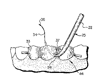
figures, a threading device 20 is shown in FIG. 1. The
threading device 20 is formed of a hollow tube comprising a
handle portion 22 and a curved reduced diameter, somewhat
flattened portion or blade-like portion 24. Preferably, the
threading device 20 is formed from a cylindrical, open-ended
tube 25 part~ally shown in phantom line in FIG. 1. In an end
of the handle 22 distal the blade-like portion 24 a fill
aperture 26 i5 located at a terminal end or blade-like
portion 24. A tip portion 30 is formed having a tip aperture
28 therethrough A neck portion 32 is defined between the
handle 22 and the blade-like portion 24 when the blade is
formed thereon.
As shown in FIG. 1, the blade-like portion 24 is
pre~erably curv~d to facilltate lnsertion between dental
lS structures 33 in di~ficult-to-r~ach place~. As shown in FIG.
2, however, the threading device 20 is generally straight.
The tubular columnar handle 22 of the threading device 20
generally exhibits mors rigidlty than the blade-like portion
24, which has been flattened somewhat during the forming
process, and is generally more flexible. Moreover,
increasing or decreasing the degree of curvature of portion
24 during formation, as compared to the illustrated
curvature, i5 within the scope of the invention.
FIG. 3 provides a cross-sectional view of the
threading devicQ 20 illustrating a charge of floss 34
retained therein. Generally, the floss 34 retained in the
handle portion 22 is coiled in order to accommodate a
predetermined length of floss 34 which is longer than the
overall length of the threading device 20, *to the threading
device 20. At approximatoly the neck port~on 32, the floss
34 is no longer coiled and instead is a generally linear
portion of ~108S ~xtending through the blade-like portion 24
and protru~ing through the tip aperture 28 formed through the
tip portion 30. A lead portion 36 of the floss extends
beyond the tip portion 30 and is preferably coated with a
substance for stiffening the same. The entire floss may be
-6-
20~6Q~'~
so coated if desired. The coated stif~ened lead portion 36
facilitates insertion o~ thQ threading devicQ 20 through
small areas 37 between dental structures 33 as heat viewed in
FIGS. 8 and 9. Further, the lead portion 36 provides a
gripping portion for pulling floss 34 from the threading
device 20.
FIGS. 4-7 illustrate transverse cro~s-sect~ons of
the threading device 20 taken along the respective section
lines as illustrated in FIG. 3 . As shown in FIG. 4, the
handle portion 22 has a g~nerally circular cross-section
providing strength and rigid$ty to the device. FIG. 5
illustrates the neck potion 32 ln which the generally
circular cross-section of the handle 22 has been flattened.
FIG. 6 illustrates a cross~section taken through the
blade-like portion 24 in which the diameter of the tube 42
has been substantially reduced or flattened and drawn. In
the cross sectional view o~ FIG. 6, the blade-like portion 24
has a ma~or axis 38 and a minor axis 40. The blade-like
portion 24 is generally in~lexible when ~orces are applied
perpendicular to the minor axis 40 but is flexible when
forces are applied perpendicular to the major axis 38 (as
indicated by arrows 41 in FIG. 3). This flexibility, or
inflexibility, ~unctions to onhance the control of the
threading device 20 when used. In FIG. 7, a cross-section is
taken through the tip portion 30.
The present invention further includes a method of
forming a dental flo88 threading device 20. The tube, from
whlch the handle 22 and blade-like portion 24 are formed, is
formed of a material having a first melting temperature. The
floss material having a sQcond mel~ing temperature which ls
greater than the first melting temperature, that of the tube.
In forming the threading device 20, a tube 25 is
provided and a charge of floss 34 is inserted therein. A
lead portion 36 of the floss 34 is retained extending from
. .
..
20~6~7~
one end of the tube 25 throughout the forming process. The
tube 25 i8 heated to approximately the first melting
temperature such that the tube 25 may be formed. At least a
portion o~ th~ heated portion o~ the tube 25 is drawn into
the blade-like portion 24 while retaining the lead portion 36
extending there~rom. ~he blade-llke portion 24 ~ormed as
such, is formed into a desired curvature shape and retained
in such shape during a ¢ooling process. A substance may be
applied to the lead portion 36 of the floss 34 to stiffen the
portion for facilitating insertion of the lead portion 36
into small gap~ 37 between dental structures 33.
As a further component of the invention, a novel
method of threading dental ~1088 between dental structures 33
~or cleaning therebetween is provided. This novel method of
threading dental ~log8 includes providing a tube 25 with a
handle portion 22 and a blade-like portion 24 having a charge
of flo8s 34 retained therein. The tube 25 is provided with a
curved blade-like portion 24 and has a pro~ecting lead
portion 36 oP the ~loss 34 which has pre~erably been coated
with a stiffening substance to promote insertion thereof, and
of the following tip portion 30 of the threader between
dental structures 33.
With reference to FIGS. 8 and 9, the method of
threading dental floss is shown. The floss 34, retained
inside of the tube 25 as described hereinabove, ls to be
inserted between dental structures from a first side 44 and a
lead portion 36 is driven underneath or between the dental
structures 33 untll at least the tip o~ the tube pro~ects
from a second side 46. Once a part of the tube 25, and the
lead portion 36 extending there~rom, extend from the second
side 46 the lead portion 36 i~ gra~ped to extract the floss
34 from the tube 25 thereby permitting movement of the floss
34 against the abutting sur~aces on the sides of the gap 37
through which the tube 25 has been inserted. In this method
o~ threading dental floss 34 between dental structures 33 it
is useful to provide a tube 25 with a curved portion 24 and
20~072
preferably havlng a reduced diameter to ~acilitate insertion
of the tube 25 into a gap 37 between dental structures 33.
Further, it i~ preferable to provide a tube 25 which has a
relatively rigid handle portion 22 so that only one hand
needs to be used to manipulate the tube 25 while inserting a
tip portion 30 into a gap 37. The tip and/or blade-like
portion 24 may be made relatively flexible to permit access
to confined areas.
While a particular embodiment of the present
invention has been shown and described in detail herein, it
may be obvious to those ~kllled in the art that changes and
modi~ications o~ the present invention in it~ various
aspects, may bR made without departing from the invention in
its broader aspects, some of which changes and modi~ications
being matters of routine engineering or design, and others
being apparent a~ter study. As such, the scope of the
invention should not be limited by the particular embodiment
and speci~ic construction described herein, but should be
defined in the appended claims and equivalents thereof.
2G Accordingly, the aim of the appended claims is to cover all
such changes and ~odi~ications as all within the true spirit
and scope of the invention.
...... .......
.
..