Note : Les descriptions sont présentées dans la langue officielle dans laquelle elles ont été soumises.
2Q461 77
_ RE~lv~K C0IL FOR A PROGRAMMABLE PROJECTILE FUZE
BACKGROUND OF THE INVENTION
1. Field of the Invention
The present invention relates to a new and improved
receiver coil or receiver coil arrangement for a programmable
projectile fuze comprising a coil core upon which there is
located a winding or coil.
2. Discussion of the 8ackground and Material Information
A programmable projectile fuze, for example as
disclosed in the published European Patent Application No.
0,300,255, published January 25, 1989 and the cognate United
States Patent No. 4,862,785, granted September 5, 1989, comprises
an apparatus for setting a counter for triggering a fuze,
especially a delayed action or time fuze, located in the
projectile after firing of such projectile. The counter is
inductively set by a transmitter coil secured forwardly or
downstream of the muzzle of the weapon by means of a receiver
coil located within the projectile. There is also provided an
apparatus for measuring the muzzle velocity of the projectile,
in order to set or adjust the counter for triggering the delayed
action fuze as a function of the muzzle velocity of the
projectile. The receiver coil is mounted upon a coil body.
In order to be able to set or adjust the delayed action
- 1 - P10051
20~ 7~
- or time fuze with the requisite accuracy, at least 12 bits must
be transmitted from the transmitter coil to the receiver coil.
Assuming that the projectile has a muzzle velocity of, for
example, about 1200 meters per second, then the flight of the
receiver coil of the projectile through the transmitter coil
secured at the muzzle of the weapon barrel occurs in a relatively
short amount of time, so that only very little time is available
for transmission of data or information from the transmitter coil
to the receiver coil. Therefore, high frequencies are required
for the transmission of such data or information.
It has now been found that with a coil core formed of
steel, there is possible the transmission of this data from the
transmitter coil to the receiver coil or receiver coil
arrangement, but such results in an undesired increase in the
weight of the projectile fuze. In order to reduce the weight of
the projectile fuze in the projectile the coil core can be formed
of aluminum. However, when this is done, then:
(a) the induced voltage in the case of an aluminum core
is appreciably smaller than for an iron core; and
(b) the positive and negative amplitudes of the induced
voltage are asymmetrical in the case of an aluminum core and not
of the same magnitude in opposite directions.
SUMMARY OF THE INVENTION
Therefore, it is a primary object of the present
invention to provide an improved receiver coil arrangement for
- 2 - P10051
2Q~
- a programmable projectile fuze which is not afflicted with the
aforementioned limitations and drawbacks.
Another and more specific object of the present
invention aims at the provision of an improved receiver coil
arrangement for a programmable projectile fuze which avoids the
aforenoted drawbacks and protects the coil winding or coil of the
projectile fuze against eddy current fields.
Still a further noteworthy object of the present
invention concerns the provision of an improved receiver coil
arrangement for a programmable projectile fuze which affords
reliable transmission of data from the transmitter coil to the
receiver coil arrangement with a fuze construction which
nonetheless possesses relatively low weight.
Now in order to implement these and still further
objects of the present invention, which will become more readily
apparent as the description proceeds, the receiver coil or
receiver coil arrangement for a programmable projectile fuze of
the present development is manifested, among other things, by the
features that an insert or insert member is arranged between the
coil core and coil winding or coil which shields or screens the
coil winding or coil against eddy current fields.
Preferably, an insert in the form of a thin, for
instance, about 0.05 millimeter thick steel band is inserted
between a coil wind ing or coil formed of copper and a coil core
- 3 - P10051
2~
formed of aluminum. This steel band dampens the magnetic fields
of the transmitter coil with such an intensity at the coil core
formed of aluminum that there are generated practically no eddy
currents. Eddy currents are likewise formed at the steel band,
but such are appreciably smaller due to the greater eddy current
resistance R (fe) of the iron.
The aforementioned insert or insert member composed of
a steel band has two different functions:
(a) Owing to the ferro-electric properties of the
steel band the magnetic lines of force are slightly compacted;
and
(b) The magnetic field lines occurring at the cylinder
composed of the steel band induce therein eddy currents. These
shield the coil carrier or core located therebelow such that
practically no eddy currents are formed within the aluminum-coil
carrier or core.
With proper dimensioning of the steel band the receiver
coil arrangement of the present invention behaves in the manner
of a coil mounted at a coil core formed of steel. As a result:
(a) The output voltage of the receiver coil
appreciably increases with the same programmable current of the
transmitter coil.
(b) The positive and negative amplitudes are of the
same magnitude.
(c) When using a thin steel foil insulated at one side
and having a number of convolutions or windings, it is possible
- 4 - P10051
77
- to further reduce the eddy currents.
BRIEF DESCRIPTION OF THE DRAWINGS
The invention will be better understood and objects
other than those set forth above, will become apparent when
consideration is given to the following detailed description
thereof. Such description makes reference to the annexed
drawings wherein there are depicted different embodiments of
receiver coils in conjunction with a programmable projectile
fuze, and specifically wherein:
Fig. 1 illustrates a longitudinal sectional view
through a muzzle of a weapon barrel equipped with an apparatus
for measuring the muzzle velocity and with a transmitter coil for
transmission of data or information to a projectile which departs
from the weapon barrel muzzle;
Fig. 2 is a longitudinal sectional view through a
projectile according to a second embodiment;
Fig. 3 is an enlarged longitudinal sectional view
through the projectile fuze of the arrangement of Fig. 2 serving
for providing a detailed explanation of the present invention;
and
Fig. 3A is an enlarged detail sectional view of a
modified construction of insert member of the projectile fuze
- S - P10051
2~
-- comprising a convoluted steel foil provided at one side or face
with an electrically insulating layer.
DETAILED DESCRIPTION OF THE PREFERRED EMBODIMENTS
Describing now the drawings, it is to be understood
that only enough of the construction of the receiver coil or
receiver coil arrangement for a programmable projectile fuze and
the associated muzzle of the weapon barrel have been depicted
therein, in order to simplify the illustration, as needed for
those skilled in the art to readily understand the underlying
principles and concepts of the present invention.
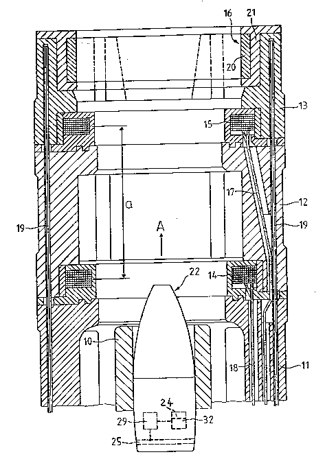
Turning attention now to Fig. 1, it will be seen that
the weapon barrel muzzle 10 is surrounded by a three-member cage
or cage structure 11, 12 and 13 which protrudes beyond the weapon
barrel muzzle 10. In the intermediate part 12 of the cage 11,
12 and 13 there is located a first measuring coil 14 and in the
forward or downstream part 13 of this cage 11, 12 and 13 there
is located a second measuring coil 15 and a transmitter coil 16.
The conventional manner of attachment of the three-member cage
11, 12 and 13 at the weapon barrel muzzle 10 and the
interconnection of the three members of such three-member cage
11, 12 and 13 with one another is well known in the art, and
thus, need not be here additionally considered or illustrated,
particularly since such does not constitute subject matter of the
invention nor is the same necessary for understanding of the
inventive concepts.
- 6 - P10051
20 4 6 1 77
~ Lines or conductors 17 and 18 serve for supplying
electrical energy to both of the measuring coils 14 and 15. A
number of soft iron rods 19, of which only two are visible in the
showing of Fig. 1, are incorporated within the three-member cage
11, 12 and 13 for shielding the entire measuring installation
against spurious or disturbing effects due to magnetic fields.
The transmitter coil 16 comprises a single winding 20 and a coil
body 21. A projectile 22 moves in the direction of the arrow A
through the apparatus for measuring the starting velocity of the
projectile 22 and for transmitting data or information, in other
words, this projectile 22 travels through both of the measuring
coils 14 and 15 and also through the transmitter coil 16. As
previously explained, this transmitter coil 16 comprises a single
winding 20 and furthermore is relatively small.
In order to determine the starting- or muzzle velocity
of the projectile 22 there is measured the time t required by the
projectile 22 to move from the measuring coil 14 to the measuring
coil 15. From the known spacing a between these two measuring
coils 14 and 15 and this time t there can be computed the muzzle
velocity V0 = a/t. When taking into account such muzzle velocity
V0 of the projectile 22 it is possible to compute the time
required for the projectile 22 to reach the target.
Consequently, a delayed action or time fuze 24 arranged in the
projectile 22 can be adjusted or set such that the projectile 22
is ignited at the region of the target. The time needed by the
projectile 22 to reach the target after exiting from the weapon
barrel muzzle 10 is transmitted in digital form from the
- 7 - P10051
20461 77
transmitter coil 16 to a receiver coil 25 located in the
projectile 22. As is usually the case and known in the art, such
transmission is accomplished by magnetic induction.
In order to set the delayed action fuze 24 with the
requisite accuracy at least twelve pulses should be transmitted
from the transmitter coil 16 to the receiver coil 25. As already
explained, since the projectile 22 moves through the transmitter
coil 16 with a velocity of approximately 1200 meters per second
it is necessary to transmit the twelve pulses at a relatively
high frequency at the proper point in time. The proper point in
time for the transmission of the pulses is determined with the
aid of the forward measuring coil 15 of the apparatus for
measuring the muzzle velocity V0. As soon as the projectile 22
has travelled through the measuring coil 15 there can be
transmitted the data or information from the transmitter coil 16
to the receiver coil or receiver coil arrangement 25. The pulses
arrive from the receiver coil 25 through a filter 29 at a counter
32 which is connected with the delayed action fuze 24. It is
here remarked by way of completeness that circuitry for achieving
the explained pulse transmission is well known in the art, as
exemplified, for instance, by the aforementioned United States
Patent No. 4,862,785, granted September 5, 1989, to which
reference may be readily had.
According to the modified showing of Fig. 2, a so-
called base fuze 40 is threadably secured by threading 42 or
- 8 - P10051
A
~0461 77
- equivalent connection means at the rear end of a projectile 41.
The individual elements of the base fuze 40 are located
internally of a fuze housing or casing 43a which also functions
as a coil core 43a and forms in conjunction with a winding or
coil 23 the previously mentioned receiver coil or receiver coil
arrangement 25. An insulating layer 44 protects the winding or
coil 23 against damage due to the presence of the hot propellant
gases. The construction of the fuze is known to the art and thus
need not be here further considered.
With reference now to Fig. 3 and considering at this
point the present invention in detail, it will be seen that at
the region of the receiver coil or receiver coil arrangement 25
an insert or insert member 45 is located between the coil or
winding 23 formed, for instance, of copper wire and the coil core
43 formed of aluminum and defined by the fuze housing or casing
43a. This insert or insert member 45 preferably comprises a
steel band, for example, formed of ferro-electric material having
high permeability ~ which is equal to or greater than 100. A
steel band thickness of 0.05 mm. is sufficient to protect the
coil or winding 23 against an eddy current field.
Moreover, and as shown for the modified construction
depicted on an enlarged scale in Fig. 3A, this steel band of the
insert or insert member 45a can comprise a one-sided insulated
steel foil 50 possessing a number of convolutions or coils 52,
wherein the electrically insulating layer 54 can be formed of a
glass-fiber reinforced epoxy resin.
- g - P10051
20461 77
Instead of using a thin steel band there can be
employed an appreciably thic~er insert or insert member 45 formed
of electrically insulating material, such as again a glass-fiber
reinforced epoxy resin, to the extent that sufficient space is
available. Due to the thus formed spacing between the copper
wire and the aluminum core there is realized a similar effect.
While there are shown and described present preferred
embodiments of the invention, it is distinctly to be understood
the invention is not limited thereto, but may be otherwise
variously embodied and practiced within the scope of the
following claims.
- lO - P10051