Sélection de la langue

Search

Sommaire du brevet 2047177 

Énoncé de désistement de responsabilité concernant l'information provenant de tiers

Une partie des informations de ce site Web a été fournie par des sources externes. Le gouvernement du Canada n'assume aucune responsabilité concernant la précision, l'actualité ou la fiabilité des informations fournies par les sources externes. Les utilisateurs qui désirent employer cette information devraient consulter directement la source des informations. Le contenu fourni par les sources externes n'est pas assujetti aux exigences sur les langues officielles, la protection des renseignements personnels et l'accessibilité.

Disponibilité de l'Abrégé et des Revendications

L'apparition de différences dans le texte et l'image des Revendications et de l'Abrégé dépend du moment auquel le document est publié. Les textes des Revendications et de l'Abrégé sont affichés :

  • lorsque la demande peut être examinée par le public;
  • lorsque le brevet est émis (délivrance).
(12) Brevet: (11) CA 2047177
(54) Titre français: STRUCTURES SOUS-MARINES ANTI-EROSION
(54) Titre anglais: UNDERWATER SOIL RETENTION STRUCTURES
Statut: Périmé et au-delà du délai pour l’annulation
Données bibliographiques
(51) Classification internationale des brevets (CIB):
  • E02B 03/04 (2006.01)
  • E02D 29/00 (2006.01)
(72) Inventeurs :
  • ALSOP, PETER (Royaume-Uni)
(73) Titulaires :
  • JOON GEOL RYU
(71) Demandeurs :
  • JOON GEOL RYU (Republique de Corée)
(74) Agent: MARKS & CLERK
(74) Co-agent:
(45) Délivré: 2001-05-29
(86) Date de dépôt PCT: 1990-02-21
(87) Mise à la disponibilité du public: 1990-09-07
Requête d'examen: 1997-02-10
Licence disponible: S.O.
Cédé au domaine public: S.O.
(25) Langue des documents déposés: Anglais

Traité de coopération en matière de brevets (PCT): Oui
(86) Numéro de la demande PCT: PCT/GB1990/000272
(87) Numéro de publication internationale PCT: GB1990000272
(85) Entrée nationale: 1991-08-23

(30) Données de priorité de la demande:
Numéro de la demande Pays / territoire Date
8904170.1 (Royaume-Uni) 1989-02-23

Abrégés

Abrégé anglais


An underwater soil retention and reinforcement
structure comprises a sequence of synthetic buoyant
fronds arranged side-by-side to form a frond line. The
frond line is folded back and forth to form an array of
fronds, and the successive folded sections of the frond
line have aligned openings threaded by at least one
anchor line for anchoring the array to the soil bed.

Revendications

Note : Les revendications sont présentées dans la langue officielle dans laquelle elles ont été soumises.


7
The embodiments of the invention in which an exclusive
property or privilege is claimed are defined as
follows:
1. An underwater soil retention and reinforcement
structure comprising a sequence of synthetic buoyant
fronds arranged side-by-side to form a frond line, the
line being folded back and forth to form an array of
fronds, and the successive folded sections of the frond
line having aligned openings threaded by at least one
anchor line for anchoring the array to the soil bed.
2. A structure according to claim 1 further
comprising means for controlling the pitch or spacing
between the successive folded sections of the frond
line.
3. A structure according to claim 2 in which the
control means comprises spacing elements slidable
along the respective anchor lines.
4. A structure according to claim 2 in which the
control means comprises foldable links between the
successive folded sections.
5. A structure according to any one of the claims
1-4 in which a ground anchor is secured at one or both
ends of each anchor line, the structure being anchored
by driving the ground anchors into the soil bed.
6. A structure according to claim 5 further
comprising means for releasably attaching at least one
additional ground anchor to at least one of the anchor
lines at a point intermediate the ends of the anchor
line.
7. A structure according to any one of claims 1 to 6
wherein the frond line comprises a continuous sheet of
synthetic buoyant material.

8
8. A structure according to claim 7 wherein the anchor
line is threaded through a reinforced base portion of the
sheet.
9. A structure according to claim 8 in which the
reinforced portion of the sheet comprises an upturned
bottom edge.
10. A structure according to claim 9 in which a flexible
reinforcing member is encased within the upturned bottom
edge portion of the sheet.
11. A method of deploying an underwater soil retention and
reinforcement structure, the structure comprising a line of
buoyant fronds folded back and forth and threaded by at
least one anchor line, and the method comprising retaining
each anchor line in a box-like dispenser with the folded
sections of the frond line in a bunched, compact s~ate, and
the fronds lying flat, lowering the dispenser to the soil
bed, anchoring one end of each anchor line to the soil bed,
and thereafter advancing the dispenser over the soil bed,
such that the anchor line is progressively withdrawn from
the dispenser and the fronds are released into an upright
buoyant state.
12. A method according to claim 11 further comprising
increasing the pitch or spacing between the successive
folded sections of the frond line along the anchor line as
the anchor, line is withdrawn from the dispenser.

Description

Note : Les descriptions sont présentées dans la langue officielle dans laquelle elles ont été soumises.

x,04 ,1~~
one of the most efiactive methods of preventing erosion of
the river or sea bed around underwater structures is by
anchoring an array or mat oz synthetic buoyant fronds close
to the structure. The fronds exert a viscous drag which
reduces the velocity of the fines (soil pa~ticles) in
underwater currents to a point where the particles are
deposited, and the deposited particles then accumulate to
form a permanent consolidated sandbank.
The array of fronds generally consists of lines of fronds
arranged in a predetermined pattern and interconnected by
fle:cible ties, or the fronds may be secured individually or
in bunches to a matting.
In either case, the difficulties of manufacturing the array
in a simple but cost-effective manner, combined with the
difficulties of deploying..the array on the river or sea
bed, have prevented the potential of the method being fully
exploited.
There is therefore the: need' for a soil retention and
reinforcement structure which can be easily deployed on the
sea bed, and which is simple to produce on a commercial
scale. Ideally, the method of deploying the structure
should lend itself to automation.
It would also be an advantage if the density and/or height
of the structure could be easily varied over a wide range
without affecting the manufacturing process.
According to one aspect of the present invention, there is
provided an underwater soil retention and reinforcement
structure comprising a sequence of synthetic buoyant fronds
arranged side-by-side to form a frond line, the line being
35, folded back and forth to form an array of fronds, and the

~~~'71.'7~
successive folded sections of the °rond line having aligned
openings threaded by at least one anchor line for anchoring
the array to the soil bed. In this manner, a curtain o:
fronds is presented to the soil particles in almost every
direction, and the pitch or spacing between the successive
folded sections is infinitely variable from a virtual solid
to whatever pitch or spacing is required.
In a preferred embodiment, the structure comprises a fan-
folded continuous sheet with vertical slits forming the
individual fronds. Ths folded sheet is initially packed in
a.box-like dispenser with the folded sections in a tightly
bunched, compact state. As the anchor~line is withdrawn
from the dispenser, the sections are spread apart.
In this manner, the density of fronds in the structure can
be regulated.simply.by.controlling~the pitch of the folded
sections. Moreover:, wince the frond ~i:ne is-a continuous
folded structure, manuFacture of a complete~array of fronds
is greatly simplified. A change in frond height is
obtained merely by changing the width-of the sheet.
The base of the sheet is preferably reinforced, and the
anchor lines pass through aligned holes in the reinforced
base section of the sheet.
One particular example of the invention will now be
described with reference to the accompanying drawings in
which:
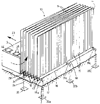
.Fig. 1 is a diagrammatic perspective view showing a scour
control.structure partially withdrawn from a dispenser and
anchored to the sea bed;
Fig. 2 is a diagrammatic underside plan view of the

~o~°~~.~~
3
structure shown in Fig. l; and
Fig. 3 is a detail of a part of the structure shown in Fig.
2 when viewed from one side and showing the attachment of
S a side anchor.
Referring to these drawings, the illustrated scour control
structure consists of a continuous sheet 10 of buoyant
synthetic material, such as polypropylene, slit into 25mm
vertical strips 11 to provide a sequence of individual
fronds each having a height of up to 2 metres above the
soil bed 12 when the structure is anchored to the bed 12.
The slits 15 terminate some distance above the bottom edge
25 16 of the sheet, and the bottom of the sheet is folded
upwards to provide a reinforced base 28. A reinforcing
strap l7 is encased within the base 18.
The, sheet 20 :is folded back and forth in a fan-folded ,
.-configuration; and is dispensed from a box 13. As best
shown in Fig. 2, the successive fan-folded sections 14 of
the folded base strip 18 are stored at the bottom of the
box l3 in a bunched'compact state, and the frond strips 11
are then laid flat and folded over in the space above. As
the sections 14 are progressively withdrawn from the bo::,
the~structure expands into an open extended state and the
frond strips 11 are released into an upright buoyant
position (Fig: 1).
The structure is threaded by anchor lines 19a, 19b, 19c
passing through aligned holes 20 in the reinforced base 18.
The lines 19 each carry adjustable sheet stops in the form
of grommets 21 which are slidable along the respective
lines and caw be used to adjust the spacing between the

iie~~'~~.'i
4
fan-folded sections 14 of the :>heet. This in turn controls
the density of the fronds in the overall structure.
Alternatively, a short foldable inter-sheet link 41 (Fig.
2) is provided between each of the successive sections 14
S which limits the pitch of the fan-folded structure. The
link may be of the same material as the sheet and
effectively forms a V-shaped hinge between each of the
successive sections 14 at the outboard edges of the
structure as shown in Fig. 2.
The use of links 41 formed of sheet material permits a
greater packing density in the dispenser 13 compared to the
use of grommets 21, and controls the pitch of the fan-
folded structure.
At the leading end of each line 19 is a ground anchor plate
22 which may be of the type more fully described in Uh
patent application 8904169.3. The anchor plates 22a, 22b,
22c are driven downwardly inao the sea bed 12 to anchor the
20, leading end of, the, structure l0.firmly to the:sea bed.
These three leading anchors 22a, 22b and 22c are initially
stored on top .of,the dispenser.-box 13. Once.. these three
anchors have been anchored,. the dispenser box 13 is
25. advanced rearwardly in the direction of arrow 23. The
leading section 14a of the fan-folded structure is attached
to the anchor lines 19 so that this rearward movement
progressively withdraws the successive sections 14 of the
sheet 10 through a throat at the bottom of the front wall
30 of the dispenser and opens out the fan-folded structure.
During this process, the anchor lines 19a,19b,19c run
through the openings 20 in the base of the fan-folded
sheet, the three lines being drawn from respective supplies
folded concertina fashion at the back of the dispenser as
35 shown in Fig.'2. At predetermined intervals, denoted for

5
e:campla by colour coding on the anchor lines 19 and/or on
the sheet 10, a side anchor 25 is secured to the respective
outside anchor lines 19a and 19c by respective anchoring
straps 24 and using a carabiner clip fastening 28 which
clips around the anchor line and passes through an aperture
26 formed in the sheet 10 along one of the fold lines 27.
Finally, three trailing anchors 40 secured by straps
(omitted for the sake of clarity) to the opposite ends of
the respective lines 19a, 19b, 19c are driven into the sea
i0 bed to complete the anchoring process.
With the structure: l0 anchored to the sea bed in the path
of an underwater current, the velocity of the current will
be reduced below the critical transport velocity so as to
'_ ensure particle deposition. Accordingly, substantially all
the fines carried by the current will be deposited within
the structure and a permanent consolidated sandbank will be
created having a particulaxly uniform distribution of
reinforcement.
2
In particular, it can be seen that the fronds present an
almost solid wall in every direction, and once the fines
enter the V-shaped pockets formed by the successive
sections of the folded sheet they are virtually trapped
since there are no clear current flow paths through the
structure.
The base pitch between successive sections might be of the
order of 20mm giving 50 frond lines per linear metre. This
30 density can be easily varied by adjusting the spacing
between the grommets 21. As illustrated, the grommets 21
are arranged so that the interleaved V-shaped pockets
formed between the successive sections 14 ehtend from one
side of the structure to the other in alternating
35 directions. However, the grommets 21 can be adjusted to

20~'~1.'~'7
6
provide any required pattern of pockets. In particular,
the grommets on the centre anchor line 19b could be
adjusted to provide a different pattern in which the
pockets terminate at the centre line.
In the alternative arrangement of Fig.2, the base pitch is
fixed by the length of the foldable intar-sheet links 41.
The front anchor plate 22 and.the side anchor plate 25 with
their respective anchoring straps 24 are stored on top of
the box 13 one behind the other so the: ~ they are easily
accessible when deploying the structure on -the sea bed.
r. ,

Dessin représentatif
Une figure unique qui représente un dessin illustrant l'invention.
États administratifs

2024-08-01 : Dans le cadre de la transition vers les Brevets de nouvelle génération (BNG), la base de données sur les brevets canadiens (BDBC) contient désormais un Historique d'événement plus détaillé, qui reproduit le Journal des événements de notre nouvelle solution interne.

Veuillez noter que les événements débutant par « Inactive : » se réfèrent à des événements qui ne sont plus utilisés dans notre nouvelle solution interne.

Pour une meilleure compréhension de l'état de la demande ou brevet qui figure sur cette page, la rubrique Mise en garde , et les descriptions de Brevet , Historique d'événement , Taxes périodiques et Historique des paiements devraient être consultées.

Historique d'événement

Description Date
Le délai pour l'annulation est expiré 2006-02-21
Lettre envoyée 2005-02-21
Inactive : TME en retard traitée 2002-03-11
Accordé par délivrance 2001-05-29
Inactive : Page couverture publiée 2001-05-28
Inactive : Taxe finale reçue 2001-02-22
Préoctroi 2001-02-22
Un avis d'acceptation est envoyé 2000-08-29
Lettre envoyée 2000-08-29
Un avis d'acceptation est envoyé 2000-08-29
Inactive : Approuvée aux fins d'acceptation (AFA) 2000-08-03
Modification reçue - modification volontaire 2000-07-10
Inactive : Dem. de l'examinateur par.30(2) Règles 2000-03-15
Lettre envoyée 1999-08-31
Exigences de rétablissement - réputé conforme pour tous les motifs d'abandon 1999-08-26
Réputée abandonnée - omission de répondre à un avis sur les taxes pour le maintien en état 1999-02-22
Inactive : Dem. traitée sur TS dès date d'ent. journal 1998-08-12
Inactive : Renseign. sur l'état - Complets dès date d'ent. journ. 1998-08-12
Toutes les exigences pour l'examen - jugée conforme 1997-02-10
Exigences pour une requête d'examen - jugée conforme 1997-02-10
Demande publiée (accessible au public) 1990-09-07

Historique d'abandonnement

Date d'abandonnement Raison Date de rétablissement
1999-02-22

Taxes périodiques

Le dernier paiement a été reçu le 2001-02-21

Avis : Si le paiement en totalité n'a pas été reçu au plus tard à la date indiquée, une taxe supplémentaire peut être imposée, soit une des taxes suivantes :

  • taxe de rétablissement ;
  • taxe pour paiement en souffrance ; ou
  • taxe additionnelle pour le renversement d'une péremption réputée.

Les taxes sur les brevets sont ajustées au 1er janvier de chaque année. Les montants ci-dessus sont les montants actuels s'ils sont reçus au plus tard le 31 décembre de l'année en cours.
Veuillez vous référer à la page web des taxes sur les brevets de l'OPIC pour voir tous les montants actuels des taxes.

Historique des taxes

Type de taxes Anniversaire Échéance Date payée
Requête d'examen - petite 1997-02-10
TM (demande, 8e anniv.) - petite 08 1998-02-23 1998-02-19
TM (demande, 9e anniv.) - petite 09 1999-02-22 1999-08-26
Rétablissement 1999-08-26
TM (demande, 10e anniv.) - petite 10 2000-02-22 2000-02-17
TM (demande, 11e anniv.) - petite 11 2001-02-21 2001-02-21
Taxe finale - petite 2001-02-22
TM (brevet, 12e anniv.) - petite 2002-02-21 2002-03-11
Annulation de la péremption réputée 2002-02-21 2002-03-11
TM (brevet, 13e anniv.) - petite 2003-02-21 2003-02-21
TM (brevet, 14e anniv.) - petite 2004-02-23 2004-02-19
Titulaires au dossier

Les titulaires actuels et antérieures au dossier sont affichés en ordre alphabétique.

Titulaires actuels au dossier
JOON GEOL RYU
Titulaires antérieures au dossier
PETER ALSOP
Les propriétaires antérieurs qui ne figurent pas dans la liste des « Propriétaires au dossier » apparaîtront dans d'autres documents au dossier.
Documents

Pour visionner les fichiers sélectionnés, entrer le code reCAPTCHA :


Pour visualiser une image, cliquer sur un lien dans la colonne description du document. Pour télécharger l'image (les images), cliquer l'une ou plusieurs cases à cocher dans la première colonne et ensuite cliquer sur le bouton "Télécharger sélection en format PDF (archive Zip)" ou le bouton "Télécharger sélection (en un fichier PDF fusionné)".

Liste des documents de brevet publiés et non publiés sur la BDBC .

Si vous avez des difficultés à accéder au contenu, veuillez communiquer avec le Centre de services à la clientèle au 1-866-997-1936, ou envoyer un courriel au Centre de service à la clientèle de l'OPIC.


Description du
Document 
Date
(aaaa-mm-jj) 
Nombre de pages   Taille de l'image (Ko) 
Revendications 2000-07-09 2 67
Abrégé 1994-03-12 1 10
Description 1994-03-12 6 174
Revendications 1994-03-12 2 53
Dessins 1994-03-12 2 54
Dessin représentatif 2001-05-01 1 23
Dessin représentatif 1999-08-22 1 27
Courtoisie - Lettre d'abandon (taxe de maintien en état) 1999-03-21 1 187
Avis de retablissement 1999-08-30 1 172
Avis du commissaire - Demande jugée acceptable 2000-08-28 1 163
Quittance d'un paiement en retard 2002-03-18 1 172
Avis concernant la taxe de maintien 2005-04-17 1 172
Taxes 2003-02-20 1 48
Correspondance 2001-02-21 1 51
Taxes 1998-02-18 1 56
Taxes 2002-03-10 1 73
PCT 1991-08-22 22 815
Taxes 2001-02-20 1 49
Taxes 1993-06-07 1 23
Taxes 2000-02-16 1 49
Taxes 1999-08-25 2 69
Taxes 2004-02-18 1 49
Taxes 1996-02-19 1 43
Taxes 1995-01-09 4 205
Taxes 1997-01-20 1 57
Taxes 1995-01-26 1 49
Taxes 1993-03-17 1 36
Taxes 1994-02-07 1 29
Taxes 1993-04-29 1 43
Taxes 1992-02-20 1 29