Note : Les descriptions sont présentées dans la langue officielle dans laquelle elles ont été soumises.
WELD ON DOWEL F~:)R< A SIE~L/CONCREl'E CCMPOSIIl~ CONSrRUCrION
The invention relates to a metal wel~-on dcwel for a steel/concre-te
composite construction with a shank or shaft, which has at one end a wel~-
on end for welding onto a steel component, whilst at the other end there
is generally a head for anchoring in the concrete.
The building industry o~fers numerous different uses for the aforementioned
dcwels, particular reference being made to the use m steel/concrete
composite constructions. For this pu~pose dcwels are weJded by means of a
known stud welding process to a steel component to be connected to the
concrete. Such a steel component can e.g. be a composite beam (for bridge
or building constructionj, a metal liner for reinforced or prestressed
concrete hollow bcdies or buildings (DE-A-3 322 998, DE-A-30 09 826) or an
anchor plate for anchoring loads in a concrete structure. Generally the
concrete is connected directly to the steel component, the latter option-
ally simultaneously forming the foLmwork or part thereof.
The load-carrying behaviour of the dcwel is of great constructional signi-
ficance for such steel/concrete ccmposite components. A distinction must
be made between tensile loads, i.e. in the direction of the dowel longi-
tudinal axis, and shear 102ds, i.e. in the directlon of the steeltconcrete
interface. Great significance is attached to the 102d-carrying behaviour
of the dowel with respect to the shear 102d, which e.g. occurs as a system-
atic load due to shear stresses between the steel and co~crete or can be
intrcduced in the form of a lo3~ to be anchored. Shear loading can also
occur e.g. as a result of thermal expansions, settlement phenomena, etc.
An important aspect of the dowel load-carrying behaviour in the case ofshear-off loading is the failure type. The failure of a dowel connection
of the aforementioned type can either occur in the form of a steel failure
(the dowel shears or tears off) or in the form of a concrete failure
(breaking out frcm a generally funnel-shaped ccncrete part). It is more
favourable for the load-carrying behaviour of the connection if a concrete
failure can be avoided, such as is also the case with most existing steel/
concrete composite ccnstructions by using sufficientl~ long do~els.
The load-carrying behaviour with respect to shear load mg is essentially
3 8 ~
determined by two parameters, namely the failure or breaking load, i.e.
the maximum shear force which can ~e absorbed by the dowel cGnnection, and
the failure or break displacement, i.e. the maximum dispLacement between
the steel component and the concrete. The load-carrying behaviour can be
clearly shcwn by plotting the shear force over the displacement as a
so-calle load-strain line~ The area under this line is referred to as
the working capacity or energy of the d~del and it is desirable for the
latter to have a high value.
The problem of the invention is to provide a dcwel of the aforementioned
type with an improved load-carrying behaviGur in the case of shear lo~ding.
The problem is solved in that at the weld-on end the shank has a portion
having a larger cross-section than the shank.
The invention takes account of the fact that with a ccnventional d~del
in the case of high 103ding wide areas of the dowel shank participate in
reducing the shear loading in the concrete, load removal mainly taking
place as a result of pressures between the dowel shank and the concrete.
As a result of the inventively reinforced portion in the vicinity of the
wel~-on end these pressures are highly concentrated in the vicinity of
said portion. Therefore the concrete displace,ment acccmpanying ~he dowel
displacement is reinforced, which leads to greater dcwel displacements and
to a more proncunced activation of further lozd removal mechanisms, such
as e g. axial tensions in the deformed or strained bolt. Tests have
surprisingly revealed that dowels having the inventively reinforced portion
not only have a much more favcurable load-carrying behaviour than conven-
tional dowels with a constant diameter over the entire length, which corr-
esponds to the shank diameter of the inventive dowel, but that also, if
the diameter of the conventional dowel correspcnds to that of the inven-
tively reinforced portion, the load-carrying behavicur of the dowel with
the constant diameter is in~erior than that of dowels with the reinforced
portion. Thus, it is unimportant for the concept of the invention whether
an inventive design of the dowel is obtained by reducing the shank cross-
section or by reinforcement in the vicinity of the weld-on end. What is
important is the marked increase in the failure displacement and the
7 ii ~ ~
resulting increase in the working capacity. It is also i~portant that a
marked increase is obtained with respect to tne failure load if the choice
is made of a dowel reinforced at the weld-on end, whilst onl~ minor
losses in cormection with the failure load occur if ~le inventive dowel
is looked upon as a dowel with a reduced shank diameter.
Particularly easy manufacturing is obtained if the shank and the portion
are constructed rotationally symmetrically to a common axis. In addition,
such a dcwel has a symmetrical load-carrying behaviour.
For specific load combinations it can also be advantageous to give the
shank and/or portion a prismatic construction~
According to a simple, preferred construction the shank and/or the portion
in each case are shaped like a straight circular cylinder. Hcwever, to
further optimize the load-carrying behaviour, -the portion can be made can-
vex in the axial direction.
Due to the fact that the portian passes into the shank with a constant
taper, a more uniform overall stressing of the dowel is achieved, particu-
larly in the vicinity of the transition from the increased cross-section
portion to the nonnal cross-secti~n shank and a notch effect, which is
undesired in conjunction with dynamic stresses is a~oided.
To ensure an adequate anchoring in the concrete, in the conventional
manner the dowel can have a head. Then, according to an embcdiment, the
head diameter is at least as large as the portion diameter.
In a preferred construction, the length to diameter ratio of the portion
is between 1:2 and 4:2 and is preferably 1:2 and 3:2. Thus, the dowel can
be welded by means of known stud wel~ing processes and a particularly
favourable strain behaviour is ensure~.
In a further preferred manner, the ratio of the length to the diameter of
the shank without a head and without a portion is approxlmately 3:1 or
greater, which ensures an adequate dowel anchoring in the cancrete and
-- 4 ~
tearing of the d~Yel from the concrete due -to the s~ear stressing is
avoi~
To optimize the working capacity of a dowel, the diame-ter ratio of -the
portion to that of the shaft is between 7:6 and 10:6 and is preferably
approximately 9:6 and/or the length ratio of the portion to that of the
shank without head and without portion is at least 1:3 and the upper limit
can be 1:8. Preferably this ra-tio i5 between 1:4 and 1:7.
It can also be provided to further improve the strain behaviour that the
portion has a stepped cross-sectional increase.
The invention is described in greater detail herei~after relative to anembcdiment and with reference to the attached drawings, wherein show:
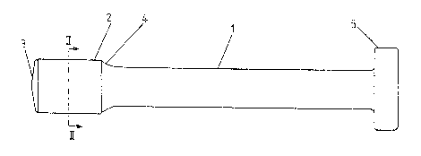
Fig. 1 A view of an inventive wel~-on dawel.
Fig. 2 A section II-II according to fig. 1.
Fig. 3 A dowel with an outwardly bulging portion.
Fig. 4 A dowel with an mwardly bulging portion.
Fig. 5 A dowel with two stepped portions.
Fig. 6 A dowel in a mcdified canstruction.
F_g. 7 A diagram with load-strain lines of two conventional and one
inventive dowel.
Fig. 1 sh,ws a weld-on dcwel with a shank 1 and a portion 2, which in each
case are shaped like a straight circular cylinder. In the represented
embcdiment the portion 2 passes unifonmly via a transition portion 4 into
the shank 1. With the free end of the portion 2, the wel~-on end 3, the
dowel is welded by means of a stud welding apparatus onto a not sho~n
steel conponent.
At the end opposite to the weld~on end, in the represented embcdiment the
dowel has a head 5, which is used for transferring stresses directed para-
llel to the longitudinal axis of the dowel between the latter and the con
crete and therefore improves the anchoring of the dowel in the concrete~
2~7~1
- 5 -
Fig. 2 shows a section II-II of the dowel acco~ding to fig. 1. It is
clearly possible to see the cir~ular cross-section of the portion 2, the
head 5 and in brolcen line form the shan]c 1. In this qmbcdiment the dia-
meter of the portion 2 is increased by appro~imately 40~ compared with the
dianeter of the shanlc 1. To ensure a gocd anchoring of the dowel in the
concrete, the di3neter of the head 5 is much larger than the portion 2.
As the porti~l 2, the shanlc 1 and the head 5 are located rotationally
symnetrically on one axis, the dowel can easily be manufact~lred.
In the assembled condition the entire dowel is inserted in th~ concrete.
In the case of a shear load, i.e. a load at right angles to the longitud-
inal axis of the dowel in the vicinity of the weld-~n end 3, high pressures
occur between the dowel and the concrete. With small she OE loads, the
pressures are concentrated in the vicinity of the weld-on endO As the
shear loading increases the size of the area of the dcwel which in this
fonn is us~d for load removal purposes is increasedO In the case of dowels
having a constant diameter over the entire length, this area can expand
to almost the entire dcwel length, as a function of the concrete compo-
sition. This more particularly applies in the case of dowels with large
diameters having a high flexural stiffness. If the diameter of the con-
ventional dowel is reduced to appm Kimately 2/3 of the original diameter
over a length of approxi~ately 80% from the head 5, then the i~ventive
dowel according to fig. 1 is obtained. In the case of high shear loads
the pressures are concentrated in the vicinity of the portion 2 with this
dowel. Ccmpared with a conventional dcwel with a dizmeter corresponding
to that of the portion 2, the transferable shear 1O2ds are somewhat lower.
However, they are clearly above the shear loads which can be transferred
by a conventional dowel with a diameter corresponding to that of the shank
1. Due to the concentration of the pressures in the vicinity of the
portion 2, the concrete is more highly stressed there than in the case of
conventional dowels. This leads to greater concrete deformations and to
an mcrease in the locally definod areas of the concrete displacement. In
turn, this allows greater dowel displacements, i.e. greater displaoements
of the dowel base, which in this case corresponds to the portion 2, at
right angles to the longit~dinal axis of the shank 1. Axial tenslons in
2~7~?)~
the dowel also increase with r~sing displ~cements. With their c ponent
parallel to the shear load, t~ese aLso make a significant contribution to
the failure load of the dowel. They also lead -to deformations of the
shank 1, which also increase the displacements of the portion 2. This
m~kes it clear that with a very great increase in tne failure displacement,
there is only a minor loss in the dowel failure load or even a marked
increase in the latter, as a function of which of the aforementioned con-
sideration methods is chosen. This wi]l be made clear hereinafter by
means of the graph of fig 7.
Figs. 3, 4 and 5 show different embodiments of the portion 2. In conjun-
ction with different concrete types, these constructions can lead to a
much better load-carrying behaviour in the case of shear loading.
In the graph according to fig. 7 are plotted the load-strain lines of three
dowels. Two of these lines, namely lines A and B, shcw the load-strain
behaviour of conventional dowels. 3Oth dcwels have the same length and a
constant cr~ss-section over the entire length. The length corresponds to
the total length of the dowel according to fig. 1. The dianeter corres-
ponds to the diameter of the shank 1 according to fig. 1 for curve A and
the diameter of portion 2 according to fig. 1 for curve B. In the graph
the shear force F is plotted in ~N over the shear displacement s in mm. s
represents the relative displacement of the steel component and therefore
also the dcwel base with respect to the concrete part. AS is clear, for
curve A and the associated dowel the failure load is approximately 80 kN
and the failure dispLacement approximately 7.S ~m, whereas for curve B and
the associated dowel the fa;lure load is approximately 155 kN and the
failure displacement approximately 9.0 mm. Curve C results from a test
carried out on a dowel according to fig. 1, whose shank diameter cver
approximately 80% of the dcwel length corresponded to that of the dcwel
according to curve A and whose diameter in the reinforced portion corres-
ponded to that of the dowel according to curve B. It can ~e seen that the
failure lo~d with approximately 140 kN is somewhat lower than for curve B,
but with approxImately 29 mm there was a marked increase in the fa;lure
displacement. These values show that for the construc~ional conditions
according to ~his ex~le the working capacity or energy of the dcwel was
~ ~ 7 ~ ~
increased by a factor of 5.5 or 3.0 compared with the dawels of curves A
and B by providing a reinforced cross-section portion. These values can
be influenced by mcdifying the constructional details.
Naturally the load-carry m g behaviour and bearing capacity of an inventive
dcwel in the case of tensile loading largely correspond to those of a con-
ventional dowel with a con~tant diameter corresponding to the diameter of
the shank 1. However, often the shear loads are decisive for the dawel
design, so that such an increased failure displace,nent, the ~arkedly
increased working capacity and the high failure loads in the shear direc
tion are much more decisive. Particular significance is attached to the
high failure d~splacenents, e.g. when using the limit design method in
composite construction. Another advantage of the reduced dowel diameter
in the shank region in accordance with fig. 1 is the fact that there is
more space for pcsitioning reinEorcing rods in the concrete. This is e.g.
significant when using anchor plates, in whose vicinity it is often
necessary to have a reinforced accumulation.