Note : Les descriptions sont présentées dans la langue officielle dans laquelle elles ont été soumises.
-- 2048226
TANK LINER-TO-OUTLET NECK SEAL
This invention relates to a method and apparatus for
protectively lining the interior of a hazardous material
tank equipped with a gravity discharge neck incorporating
a control valve at its discharge end and wherein the
liner for the tank comprises a flexible plastic liner
having a gravity outlet nipple therefore downwardly
- telescoped into and sealingly secured relative to the
outlet neck of the tank upstream from the control valve
thereof.
Various different forms of lined receptacles, sleeved
containers and shipping containers heretofore have been
provided for hazardous and non-hazardous materials.
Examples of these previously known devices are disclosed
in U.S. Patent Nos. 3,086,679, 3,169,690, 4,635,814,
4,700,867 and 4,771,917. However, these previously known
constructions do not include the overall combination of
structural and operational features incorporated in the
instant invention.
The instant invention incorporates a rigid tank
construction including an upper access opening and a
bottom wall gravity flow outlet neck provided with a
valve on its outlet end. A thin, flexible plastic liner
is disposed and confined within the tank and includes a
semi-rigid gravity flow outlet nipple in the bottom
thereof which projects downwardly into the outlet neck of
the tank and a rubber-like sealing sleeve is telescoped
over the nipple and downwardly into the outlet neck with
the sleeve radially compressed between the external
surfaces of the nipple and the internal surfaces of the
outlet neck to thereby form a fluid tight seal
therebetween such that head pressure of liquid within the
liner may not cause back flow linkage of the liquid
between the internal surfaces of the outlet neck and the
'- 2o43226
external surfaces of the liner nipple and thus flow of
the liquid into the interior of the tank externally of
the liner.
The main object of this invention is provide a method
and apparatus of transporting hazardous liquids within a
reusable transport tank in a manner eliminating the need
for cleansing the internal surfaces of the tank between
shipments of liquid therein.
Another object of this invention is to provide a
method and apparatus of transporting hazardous and non-
hazardous liquids in reusable tanks that will greatly
reduce the costs incident to such transport of liquids
and which will greatly reduce the volume of hazardous
material contaminated cleaning liquids which must be used
to clean such reusable tanks between shipment of
hazardous material liquids therein.
Yet another object of this invention is to provide a
method and apparatus in accordance with the preceding
objects and which may be practiced in conjunction with
reusable shipping tanks of various sizes and shapes.
A final object of this invention to be specifically
enumerated herein is to provide a method and apparatus in
accordance with the prece~;ng objects and which will
conform to conventional forms of manufacture, be of
simple construction and easy to use so as to be
economically feasible, long-lasting and relatively
trouble free.
These together with other objects and advantages
which will become subsequently apparent reside in the
details of construction and operation as more fully
hereinafter described and claimed, reference being had to
the accompanying drawings forming a part hereof, wherein
20 4 822~
like numerals refer to like parts throughout.
Figure 1 is a perspective view of a typical form of
hazardous materials shipping tank incorporating the liner
of the instant invention;
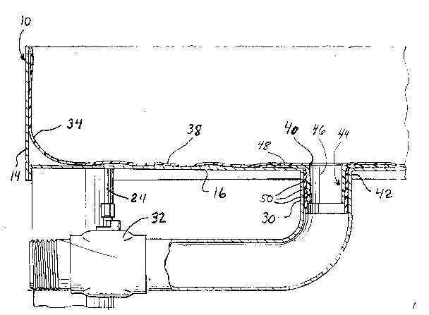
Figure 2 is an enlarged fragmentary vertical
sectional view taken substantially upon the plane
indicated by the section line 2-2 of Figure l;
Figure 3 is a fragmentary bottom perspective view of
the liner for the shipping tank illustrating the tapered
outlet nipple thereof; and
Figure 4 is an enlarged exploded perspective of the
liner outlet nipple and the associated seal sleeve to be
used in conjunction therewith, parts of the seal sleeve
being broken away and illustrated in vertical section.
Referring now more specifically to the drawings the
numeral 10 generally designates a typical form of
reusable shipping tank for hazardous materials. The
shipping tank 10 includes peripherally extC~n~ing side
walls 12 having lower margins 14 interconnected by a
bottom wall 16 extending and secured between the lower
margins 14 and the tank 10 additionally includes a top
wall 18 extending and secured between upper margins 20 of
the side walls 12 and including a central opening 22
therein.
The tank 10 is generally square in plan shape and
includes four corner depen~ing feet 24 whereby the tank
may be supported from a support surface 26 with the
bottom 16 elevated above the surface 26 and the four
corners of the top wall 18 include reinforcement plates
28 supported therefrom adapted to have the lower ends of
feet 24 of a second tank 10 disposed thereabove
positioned thereon.
2048226
The bottom wall 16 includes a rigid, tubular
downwardly projecting outlet neck 30 opening upwardly
into the interior of the tank 10 and including a control
valve 32 at its discharge end. The valve 32 and neck 30
are disposed within the peripheral confines of the tank
10 and are spaced above the lower ends of the feet 24.
Thus, the outlet 30 and valve 32 are protected against
impact by adjacent articles.
A flexible liner 34 of a size and shape to be
conformingly received within the interior of tank 10 is
provided and the upper end of the liner 34 is open as at
36 and projects outwardly through the opening 24. The
liner 34 is constructed of a suitable plastic and may be
between two and twenty mil in thickness. Further, the
bottom 38 of the liner 34 includes a central opening 40
registered with the inlet end 42 of the outlet neck 30
and an outlet fitting referred to in general by the
reference numeral 44 is provided for the liner 34.
The fitting 44 includes an upstAn~;ng tubular nipple
46 which is downwardly tapered and includes an integral
upper end flange 48 which is horizontal and diametrically
enlarged. The flange 48 has its upper surface sealingly
secured, in any convenient manner, to the underside of
the bottom 38 of the liner 34 about the opening 40 and
the nipple 46 includes a plurality of circumferentially
extending and radially outwardly projecting ribs 50 which
are generally saw-toothed shaped in cross section, see
Figure 2.
Also, an upstanding and downwardly tapering sealing
sleeve 52 is provided and constructed of a synthetic
rubber-like material. The fitting 44 may be constructed
of polyethylene and, therefore, is semi-rigid. Of
204822~
course, the sleeve 52 is somewhat resilient.
The liner 34 is downwardly inserted into the tank 10
through the opening 22 and the tapered sleeve 52, whose
upper end could be provided with a flange such as flange
S 48, has its large diameter end slightly telescoped over
the lower end of the nipple 46. Then, the lower end of
the sleeve 52 is telescoped into the inlet end 42 of the
outlet 30 and downward pressure is applied to the flange
48, whereby the nipple 46 is forced into the sleeve 52
and the sleeve 52 is forced downwardly into the inlet end
42 of the outlet neck 30 with the sleeve 52 being
radially compressed between the outer surfaces of the
nipple 46 and the inner surfaces of the inlet 42 of the
outlet neck 30. In this manner, a fluid tight seal is
formed between the nipple 46 and the internal surfaces of
the inlet end portion 42 of the outlet neck 30.
Any hazardous fluent material then may be introduced
into the interior of the liner 34 from open upper end 36
thereof and the upper end 36 of the liner 34 then may be
sealingly closed.
The valve 32 is closed, but because of the fluid
tight seal between the nipple 46 and the internal
surfaces of the inlet end of the outlet neck 30 the head
pressure of fluent material within the liner 34 above the
bottom wall 16 is inoperative to cause the fluent
material within the outlet neck 30 to backup between the
nipple 46 and the internal surfaces of the inlet 42 of
the outlet neck 30 and move into the area between the
internal surfaces of the tank 10 and the external
surfaces of the liner 34.
The tank 10 then may be shipped to a predetermined
location and the fluent material therein may be drained
204 ~226
therefrom by opening the valve 32. After the fluent
material has been drained from the liner 34, the empty
liner 34 may have the portion thereof disposed within the
tank 10 pushed to one side and a work person may enter
the interior of the tank 10 through the opening 22 and
exert an upward pull on the liner and the flange 48 to
upwardly withdraw the nipple~ 46 and sleeve 52 from
within the outlet neck 30. Thereafter, the liner 34,
fitting 44 and sleeve 52 are upwardly removed through the
opening 22 and the interior and exterior of the outlet
neck 30 may be suitable cleansed with a cleaning liquid.
Inasmuch as the interior of the tank above the inlet
end of the outlet neck 30 has not been contaminated with
the hazardous fluent material previously shipped in the
tank 10, only a sufficient quantity of cleaning liquid
need be used to clean the interior and exterior of the
outlet neck 30 and valve 32, thus conserving on cleaning
liquid and further greatly reducing the volume of
cleaning liquid which must controllably disposed of.
The foregoing is considered as illustrative only of
the principles of the invention. Further, since numerous
modifications and changes will readily occur to those
skilled in the art, it is not desired to limit the
invention to the exact construction and operation shown
and described, and accordingly, all suitable
modifications and equivalents may be resorted to, falling
within the scope of the invention.