Sélection de la langue

Search

Sommaire du brevet 2048403 

Énoncé de désistement de responsabilité concernant l'information provenant de tiers

Une partie des informations de ce site Web a été fournie par des sources externes. Le gouvernement du Canada n'assume aucune responsabilité concernant la précision, l'actualité ou la fiabilité des informations fournies par les sources externes. Les utilisateurs qui désirent employer cette information devraient consulter directement la source des informations. Le contenu fourni par les sources externes n'est pas assujetti aux exigences sur les langues officielles, la protection des renseignements personnels et l'accessibilité.

Disponibilité de l'Abrégé et des Revendications

L'apparition de différences dans le texte et l'image des Revendications et de l'Abrégé dépend du moment auquel le document est publié. Les textes des Revendications et de l'Abrégé sont affichés :

  • lorsque la demande peut être examinée par le public;
  • lorsque le brevet est émis (délivrance).
(12) Demande de brevet: (11) CA 2048403
(54) Titre français: TETE DE COUPE ROTATIVE
(54) Titre anglais: ROTARY CUTTING HEAD
Statut: Réputée abandonnée et au-delà du délai pour le rétablissement - en attente de la réponse à l’avis de communication rejetée
Données bibliographiques
(51) Classification internationale des brevets (CIB):
  • E21C 25/16 (2006.01)
  • E21C 35/23 (2006.01)
(72) Inventeurs :
  • BARBER, PETER (Royaume-Uni)
(73) Titulaires :
  • HYDRA TOOLS INTERNATIONAL PLC
(71) Demandeurs :
  • HYDRA TOOLS INTERNATIONAL PLC (Royaume-Uni)
(74) Agent: ROBIC AGENCE PI S.E.C./ROBIC IP AGENCY LP
(74) Co-agent:
(45) Délivré:
(22) Date de dépôt: 1991-08-08
(41) Mise à la disponibilité du public: 1992-02-18
Licence disponible: S.O.
Cédé au domaine public: S.O.
(25) Langue des documents déposés: Anglais

Traité de coopération en matière de brevets (PCT): Non

(30) Données de priorité de la demande:
Numéro de la demande Pays / territoire Date
9018095.1 (Royaume-Uni) 1990-08-17

Abrégés

Abrégé anglais


- 8 -
ABSTRACT
ROTARY CUTTING HEAD
A rotary, mineral cutting head (1), comprising two
parts being a base (2), which has means for attachment to a
machine, and a dome (3), which is adapted externally to carry
pick-receiving boxes (11), with a water gallery (15) defined
between an external portion (17) of the base (2) and an
internal portion (16) of the dome (3), and with the two parts
(2, 3) releasably secured together by bolts or studs (22).

Revendications

Note : Les revendications sont présentées dans la langue officielle dans laquelle elles ont été soumises.


- 6 -
WHAT I CLAIM IS:-
1. A rotary, mineral cutting head, comprising two
parts one of said parts being a base, which has means for
attachment to a machine, and the other of said parts being a
hollow interior dome, which is adapted, externally, to carry
pick-receiving boxes, with a water gallery defined between an
external portion of said base and an internal portion of said
dome, and with said two parts secured together by releasable
means.
2. A head as claimed in Claim 1, wherein said
releasable means comprises a plurality of bolts.
3. A head as claimed in Claim 1, wherein internal
surfaces of said head are plated after pick boxes have been
welded externally to said dome.
4. A head as claimed in Claim 1, wherein a radially
extending planar seating surface is provided on said dome and
a corresponding seating surface is provided on said base, with
said seating surfaces abutting one another, and a deformable
water sealing ring located between said dome and said base.
5. A head as claimed in Claim 2, wherein said bolts
pass through plain holes about a common pitch circle of said
base into correspondingly located, blind tapped holes in said
dome, longitudinal axes of said bolts being parallel to the
axis about which said head is rotatable.
6. A head as claimed in Claim 1, wherein a
projecting, generally cylindrical nose is provided on said
base, which nose substantially fills said hollow interior

- 7 -
dome, and a central water inlet bore is provided in said nose
to convey water to an annular distribution gallery defined by
external surfaces of said nose and internal surfaces of said
dome, a plurality of water distribution nozzles provided
externally on said dome, and a plurality of water supply
passageways provided in wall structure of said dome and
communicating said nozzles with said gallery.

Description

Note : Les descriptions sont présentées dans la langue officielle dans laquelle elles ont été soumises.

ROTARY CUTTING HEAD
This invention relates to a rotary cutting head
particularly, though not exclusively, for the cutting of
minerals such as rock by a so-called roadheader machine for
example.
With such a machine, the cutting head is usually
hollow and is mounted at one end of a boom carried on a
machine chassis, with the boom capable of being displaced to
various positions to cut a roadway or tunnel to the desired
profile. As a means of minimising the airborne dust
generated, conventional practice is to provide a pressurised
water supply to the cutting head for discharge from a
plurality of water spray nozzles located at various points
around the head, usually in the vicinity of picks with which
the head is armed, and also usually in the vicinity of a
terminal collar at one end of the head. In order not only
to maintain water pressure but also to minimize weakening of
the head, the head is provided with relatively fine ~e.g. 5
mm) distribution passageways, but inevitably in the course of
manufacture/repair/refurbishing difficulties are encountered
in ensuring tha~ all~ the drillings are removed from the
passageways, so as to avoid their blockage o the water flow.
~; Currently, such heads are produced in~two or more; ~ , ;
parts, principally from a sold bar or castingj and machined,
.
with the parts then welded together, with an internal water
gallery defined between the welded parts. However, machining
~:
swarf or weld splatter cannot always be detected and/or
:.
.. .: : -, - . ~ . .: : - . :

- 2 ~ r3
flushed out and conse~uently these debris might inadvertently
cause blockage of water passageways. In addition, despite
the use of ~ilters, "clean" water supply cannot always he
guaranteed, particularly in mine conditions, and conse~uently
contamination might be introduced into the head by the water
supply. Furthermore, because of the welded construction, any
blocked head must be returned to the surface for disassembly
and re-welding, if a coal mine is involved.
On examination of used heads, it is discovered that
although, as indicated previously, the water entering the head
is filtered, there is a residue of sludge, possibly formed by
the rusting of the internal parts of the head.
According to the present invention there is providea a
rotary, mineral cutting head, comprising two parts being a
lS base, which has means for attachment to a machine, and a dome,
which is adapted externally to carry pick-receiving boxes,
with a water gallery defined between an external portion of
the base and an internal portion of the dome, and with the two
parts releasably secured together by bolts or studs.
Thus, the head in accordance with the invention by
avoiding welds avoids potential contamination by weld splatter
but furthermore provides the advantagous possibility of
disassembly underground to clear any blockage, resulting in
minimum down time.
Furthermore, it has been proposed to counter the
propensity to rust by plating, e.g. with nickel, internal
surfaces of the head, and with the two-part construction in
accordance with the invention, re-plating can if necessary be
,
.' '
: .

- 3 ~ 3
effected as this may be done after the pick boxes are welded
externally to the dome so that the resultant temperature
increase during box weldlng is not permitted to hava a
deleterious effect on the nickel etc. plating.
Preferably, the dome is provided with a radially
extending planar seating face adapted to abut a corresponding
seating face of the base; and a deformable water sealing ring
may be strategically located between the dome and base.
Securing of the two parts together may be by a plurality of
bolts, e.g. eight, passing through plain holes about a common
pitch circle of the base into correspondingly located, blind
tapped holes in the dome, the bolt axes being parallel to the
axis of rotation of the head. Preferably, the base is
provided with a projecting, generally cylindrical nose which
substantially fills the hollow interior of the dome and has a
central water inlet bore to convey water to an annular
distribution gallery in fluid flow communication with a
plurality of water supply passageways leading to water
distribution nozzles.
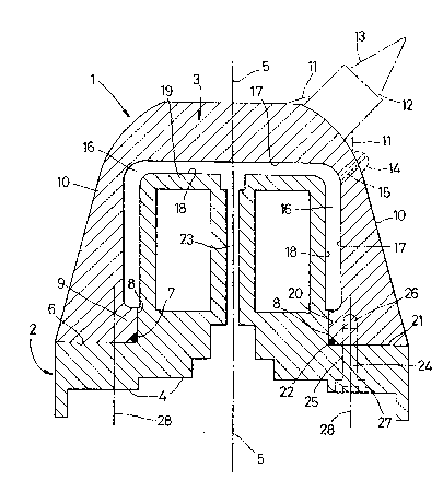
The invention will now be described in greater detail,
by way of example with reference to the accompanying drawing,
which is an axial sectional view through a head in accordance
with the invention.
The head 1 comprises a first part, being a base 2, and
a second part, being a hollow interior dome 3. The base 3 is
provided with a stepped abutment surface 4 of a profile to
match that of a complementary support surface of a boom (not
shown), of a road header machine (not shown), to which boom
' '.
- , . .
,. , - :
: ~. ~ . -
,
.

- 4 - ~ r~
the head 1 is attachad by conve~tional means, to be powered
about an axis of rotation 5.
The dome 3 is provided at an inner end with a radially
extending, planar seatiny surface 6 leading, ~ia a chamfer 7
s to a circumferential location surface 8 of an internal
mounting collar 9. At selected locations around an external
surface 10 of the dome 3 are secured, by weld metal 11, a
plurality of pick boxes 12 each housing a replacable pick 13.
Also welded at selected locations to the external surface 10
are a plurality of water spray nozzles 14 in fluid flow
communication with a water supply passageway 15 pro~ided in
the wall structure of the dome and extending to an annular
water distribution gallery 16 deined between internal
surfaces 17 of the dome 3 and external surfaces 18 o~ a
cylindrical nose 19 integral with, and projecting from, the
base 2 and substantially filling the hollow interior of the
dome 3. The nose 19 is also provided with a circumferential
location surface 20 of diameter such that the location surface
8 is a close fit on the surface 20, the latter terminating at
a radially extending, planar seating surface 21 of the base 2,
with a deformable water sealing ring 22 located between the
chamfer 7 and a corner defined at the junction of surfaces 20
and 21, while a central water inlet bore 23 serves to convey
water from a supply source on the boom to the passageways lS
and hence to the nozzles 14.
The dome 3 is secured to the base 2 by a plurality of
studs 24 (typically eight) located about a common pitch circle
and passing throtlgh plain holes 25 in the base 2 and into co-
.,
,
-: :
-~ .. . .
:
~ ' :... ... .

~ 3
-- 5
axial tapped holos 26 in the dome 3, the holes 25 being
countersunk to accommodate bolt heads 27, and the bolt axes 28
being parallel to the axis o rotation 5.
, :
.
. , .
~: . .. - , . . .
.;~: . ~ , : . : , . .
:: ' :' :'
,

Dessin représentatif
Une figure unique qui représente un dessin illustrant l'invention.
États administratifs

2024-08-01 : Dans le cadre de la transition vers les Brevets de nouvelle génération (BNG), la base de données sur les brevets canadiens (BDBC) contient désormais un Historique d'événement plus détaillé, qui reproduit le Journal des événements de notre nouvelle solution interne.

Veuillez noter que les événements débutant par « Inactive : » se réfèrent à des événements qui ne sont plus utilisés dans notre nouvelle solution interne.

Pour une meilleure compréhension de l'état de la demande ou brevet qui figure sur cette page, la rubrique Mise en garde , et les descriptions de Brevet , Historique d'événement , Taxes périodiques et Historique des paiements devraient être consultées.

Historique d'événement

Description Date
Inactive : CIB de MCD 2006-03-11
Le délai pour l'annulation est expiré 1994-02-08
Demande non rétablie avant l'échéance 1994-02-08
Réputée abandonnée - omission de répondre à un avis sur les taxes pour le maintien en état 1993-08-09
Inactive : Demande ad hoc documentée 1993-08-09
Demande publiée (accessible au public) 1992-02-18

Historique d'abandonnement

Date d'abandonnement Raison Date de rétablissement
1993-08-09
Titulaires au dossier

Les titulaires actuels et antérieures au dossier sont affichés en ordre alphabétique.

Titulaires actuels au dossier
HYDRA TOOLS INTERNATIONAL PLC
Titulaires antérieures au dossier
PETER BARBER
Les propriétaires antérieurs qui ne figurent pas dans la liste des « Propriétaires au dossier » apparaîtront dans d'autres documents au dossier.
Documents

Pour visionner les fichiers sélectionnés, entrer le code reCAPTCHA :


Pour visualiser une image, cliquer sur un lien dans la colonne description du document. Pour télécharger l'image (les images), cliquer l'une ou plusieurs cases à cocher dans la première colonne et ensuite cliquer sur le bouton "Télécharger sélection en format PDF (archive Zip)" ou le bouton "Télécharger sélection (en un fichier PDF fusionné)".

Liste des documents de brevet publiés et non publiés sur la BDBC .

Si vous avez des difficultés à accéder au contenu, veuillez communiquer avec le Centre de services à la clientèle au 1-866-997-1936, ou envoyer un courriel au Centre de service à la clientèle de l'OPIC.


Description du
Document 
Date
(aaaa-mm-jj) 
Nombre de pages   Taille de l'image (Ko) 
Abrégé 1992-02-17 1 14
Revendications 1992-02-17 2 50
Dessins 1992-02-17 1 36
Description 1992-02-17 5 173
Dessin représentatif 1999-07-04 1 25