Note : Les descriptions sont présentées dans la langue officielle dans laquelle elles ont été soumises.
~L~ ~~~
~'LO'inJ C~NTROT~ I5Ei11 CE
This invention relates to the method and means for
controlling the rate of flow of supply gas to the burner or
torch of a spectrometer. Examples of such supply gases are
fuel gases and oxidising agents as used in atomic absorption
spectroscopy, and plasma and auxiliary gases as used in
inductively coupled plasma spectroscopy. It will be
convenient to hereinafter describe the invention with
particular reference to an atomic absorption (AA)
spectrometer, but the invention could be used with other forrns
of spectrometers such as inductively coupled plasma emission
spectrometers and inductively coupled plasma mass
spectrometers>
The operation of AA spectrometers is such that the flow
rates of the gases supplied to the burner need to be closely
controlled, and it is important that the means for changing
the flow rate operates rapidly and reproducably so, in order
that the results obtained from the AA spectrometer are
accurate.
One commercially available prior art system employs a
constant gas pressure across an orifice and control of gas
flow is achieved by varying the size of the orifice. This is
conveniently done by employing a needle valve, the position of
the needle being varied using a stepper motor. A pressure
regulator upstream of the valve ensures the pressure across
the needle valve remains constant. Because the relationship
between flow and needle valve shaft angle is quite uncertain
both within any one valve and from one valve to another, it is
not possible to obtain satisfactory performance with an open
loop control configuration. Accordingly a separate transducer
is used to measure the actual flow downstream of the needle
valve and this informatiow is combined with the needle
position information in a closed loop arrangement in a control
facility: The control facility, which is conveniently a
microprocessor, is part of this control loop, and must respond
in real time to control the system.
The closed loop system has a slow response time since
the stepper motor takes a long time to position the needle
valve and overall loop stability requirements impose still
KH - 2 -
CA 02050412 2001-03-06
66147-107
further speed limitations. This slow rate of response is
undesirable in rapid sequential types of instrument, and can
also necessitate the addition of further complications in the
pneumatic circuitry, such as the inclusion of means to allow
rapid increase in fuel gas when changing oxidizing agent.
The incorporation of the microprocessor in the
control loop places a significant real time load on the
processor, reducing time available for other functions, and
renders the system susceptable to software malfunctions.
Prior art flow control systems tend to be costly
because of the large number, and expense, of components
required. Clearly the stepper motors conventionally used, and
the needle valves themselves, are expensive items, and since
two separate valves are used, one for each gas supply, the
valves and controls add significantly to the overall cost of
the AA spectrometer.
It is an object of the invention to provide a method
of controlling gas flow in a spectrometer, the use of which
will at least ameliorate the above problems. A further object
is to provide a flow control device for use in a spectrometer,
which utilises the method and is able to accurately control the
rate of fluid flow through a conduit without feedback and able
to establish or change a flow very rapidly. Another object of
the invention is to provide a flow control device which is
easily controllable by electrical or electronic means. Still
another object of the invention is to provide a spectrometer
having an accurately controllable supply gas system.
In accordance with one aspect of the present
invention, there is provided an optical spectrometer gas supply
flow control system, the method of controlling flow of said
-3-
CA 02050412 2001-03-06
66147-107
supply gas to an atomizer of said spectrometer comprising,
using an open loop flow control technique employing the steps
of: (a) providing a fixed pressure head to an electric valve
for forcing said supply gas through said electric valve;
(b) switching said valve between a maximum open position and a
minimum open position in response to a pulsed electrical signal
provided to said valve, said pulsed electrical signal having a
space time and a mark time wherein said space time corresponds
to the time in which said valve is in said maximum open
position and said mark time corresponds to the time in which
said valve is in said minimum open position; (c) controlling
the ratio of mark to space time to control the average flow
rate through said valve wherein said average flow rate equals
Fmin (B/A)+ Fmax ((A-B)/A) where Fmax is maximum flow and Fmin
is minimum flow, and where B is mark time and A-B is space time
and A equals the total of mark time plus space time.
In accordance with another aspect of the invention
there is provided a spectrometer supply gas valve including a
passage for transfer of supply gas from one location to
another, a closure member movable between a first position at
which it provides maximum obstruction to said gas transfer and
a second position at which it provides minimum said
obstruction, and control means which is responsive to a pulsed
electrical signal to cause said closure member to switch
repeatedly and in a controlled manner between said two
positions, the arrangement being such that the flow rate of gas
through said passage is determined by the aggregate of the
times the closure member resides in one or each of said
positions during a given time period, and said flow rate is
changed by varying the pattern of said signal.
-4-
CA 02050412 2001-03-06
66147-107
In accordance with still another aspect of the
invention, there is provided an optical spectrometer supply gas
flow controller comprising: (a) an electrical operable valve
for passing said supply gas; (b) means to provide a
pressurized supply gas to said electric valve under fixed
pressure; (c) means to cause said electrically operable valve
to switch responsive to electric pulses only between full open
position and full closed position; (d) pulse controller means
to provide said electric pulses, said pulses having a mark off
time and space on time, and whereby the flow rate of said
supply gas through said electric valve is proportional to the
ratio of said space on time to said space on time plus said
mark off time, wherein said space on time corresponds to the
time in which said valve is in said full open position and said
mark off time corresponds to the time in which said valve is in
said full closed position.
Reference throughout this specification to residence
of the device or the closure means in a flow condition is not
to be understood as necessarily meaning that the device or
closure member lingers for a significant period of time in
either flow condition during a switching cycle. In some
circumstances, the manner of switching may be such that the
device commences to move out of a flow condition immediately,
or almost immediately, that flow condition is adopted.
Switching is controlled by the pattern of the pulsed signal,
and that pattern is determined by the duration of each pulse
and the pulse frequency during the relevant time period. A
variation in the pattern of the signal may involve a change in
the pulse duration, or frequency, or both.
A method as described above controls, in an accurate
manner, the percentage of a given time period during which the
-5-
66147-107
CA 02050412 2001-03-06
flow control device or closure means is in each of the two flow
conditions. By varying the aggregate of the times during which
the device or closure member is in either or both of those
conditions over any given time period, it is possible to
accurately establish a particular flow rate through the device
and any associated conduit.
It is possible that some obstruction to flow will
exist in the maximum flow condition, and the minimum flow
condition may or may not be a no-flow condition.
In a preferred arrangement, the closure means
referred to above is in the form of a member mounted on a
support body for relative movement so as to be able to control
the flow of gas through an associated orifice or passage. The
member may be rapidly moved between the maximum and minimum
flow conditions by a pulsed electrical current as discussed
above.
Finally there is provided a new method of using an
electrically operable valve comprising: (a) inserting said
electrically operable valve in a conduit between a pressure
source of gas and an optical spectrometer atomizer, said valve
having a fully open position and a fully closed position; and
(b) controlling the flow rate of said gas in said conduit by
adjustably controlling the duty cycle ratio of said
electrically operable valve, where said duty cycle is the ratio
of time in fully open position to the sum of the time in the
fully open plus fully closed positions.
-6-
CA 02050412 2001-03-06
66147-107
In operation, the nature and arrangement of the
closure member can be selected relative to other features such
as the size of the associated orifice or passage, so as to
provide a desired maximum rate of flow when in the fully open
condition. When the closure member is closed, the flow through
the device may be substantially zero (depending on the fluid
leakage between valve and seat). To establish a flow between
zero and the maximum, the closure member is repeatedly switched
between the open and closed positions while accurately
controlling the fraction of the total time for which the
closure member is in the open position. Under such conditions,
the flow through the valve body will consist of a pulsing fluid
flow with the average flow equal to the maximum flow multiplied
by the fraction of total time for which the valve member is in
the open state. This is shown in Figures 2 and 3 for this
arrangement; average flow = Fmin (B/A) + Fmax ((A-B)/A).
It will be appreciated that any valve will take some
time to move from a fully open position to a fully closed
position and vice versa. During these transition periods the
actual flow will not be accurately determinate. Various
factors such as the closing and opening forces, and mass of
valve closure member will vary the flow characteristics. The
accuracy of the system will be enhanced if the times for which
the valve remains open and closed are significantly longer than
the time taken by the valve to move between the open and closed
positions.
In some applications it is desirable that the flow is
substantially smooth rather than pulsed. To achieve this it is
necessary to provide means of averaging the flow and this can
conveniently be achieved by one or more expansion chambers.
-6a-
CA 02050412 2001-03-06
66147-107
However, the slower the pulse rate (period A in Figure 2) the
more difficult it is to achieve smooth flow, and also the
longer the response time of the system to a change in setpoint.
It is therefore preferred that the pulse rate be as fast as
possible, and a pulse rate of about 27.5 Hz has been found
satisfactory. Different pulse rates may be selected according
to the requirements of the particular system.
Embodiments of the invention are described in detail
in the following passages of the specification which refer to
the accompanying drawings. The drawings, however, are merely
illustrative of how the invention might be put into effect, so
that the specific form and arrangement of the various features
as shown is not to be understood as limiting on the invention.
In the drawings:
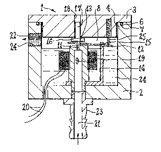
Figure d, is a diagrammatic cross-sectional view of
one form of flow control valve which incorporates an embodiment
of the invention.
Figure 2, is a graph representing a pulsed electrical
signal used to control opening and closing of the valve shown
in Figure 1.
Figure 3, is a graph representing the response of the
valve of Figure 1 to the pulsed signal represented by Figure 2.
Figure 4, is a graph representing a variation in
voltage
-6b-
4' 6 ~~ :~~; 7
~'~,J~.< .,'..!~
supply during the generation of each pulse represented by
Figure 2, but in which the time periods are shown an a
different seal to that of Figures 2 and 3.
Figure 5 is a graphical representation of the mark/space
signal from a processor which controls the valve so as to
produce the pulse frequency and duration represented by Figure
4.
Figure 6 is a representation of one form of circuit for
achieving the voltage change diagrammatically represented by
Figure 4.
Figure 7 is a diagrammatic representation of a
spectrometer incorporating a flow control device according to
the invention.
The particular flow control device shown in Figure 1
comprises a hollow housing 2 having a cap 3 fitted to an open
upper end 4 of the housing 2. Preferably the cap 3 and the
housing 2 are bolted together, but other securing means could ,
be adopted, and the cap 3 fits into the upper end 4 of the
housing 2. An O-ring seal 6 may be located in a groove 7 in
the upper end 4 of the housing to provide a fluid tight seal
between the housing 2 and the cap 3. The housing 2 and the
cap 3 are preferably made from a non-magnetic material such as
aluminium or plastics material. A chamber 8 is farmed within
the housing and a flow conduit 9 is mounted to the base 10 of
the housing so as to project axially upwardly from the base
10. A restrictor 11 is formed at the upper end of the conduit
9 and the size of this res~'trictor 11 is selected to set the
maximum flow rate through the device 1. This restriction 11
can be made so as to be adjustable but, for ease of
construction, it is preferred that the size of the restrictor
11 is fixed and is determined by machining detail.
A valve closure member 12 is mounted within the chamber
8 so as to be movable towards and away from the end face 13 of
the ~anduit 9. Preferably the valve closure member is
pivotally connected to a yoke 14 through a pivotal connection
15 and is spring biased by means of a compression spring 25
into an open position, ie. a position in which the valve
closure member 12 allows maximum flow through the restrictor
11.
KH - 7 -
w> ~~ l _~
It is preferred that the conduit 9 and the valve member
12 are formed of a magnetic material and in this regard it is
further preferred that these two components are made from a
magnetic grade of stainless steel for corrosion resistance.
Other materials might be suitable.
The valve member 12 in effect comprises an armature
which is movable relative to the restrictor 11. It is
preferably movable to a fully open position which is defined
by an adjustable stop member 16 which is mounted in the end
cap 3. The stop member 16 preferably includes a scxew
threaded shank 17 which is in cooperable engagement with a
threaded bore 18 in the end cap 3. The bore 18 may be coaxial
with the conduit 9 but that is not essential. The position of
the stop member 16 can be varied by screwing the shank towards
or away from the end face 13. The armature or valve member 12
is driven to its open position by suitable biasing means such
as a compression spring 25, and is thus biased to a fully open
position.
A coil 19 which is wound around the conduit 9 is adapted
to create a magnetic field such as to attract the armature 12
against the end face 13 and thereby close the restrictor 11,
when electrical current flows in the coil 19. For that
purpose, the coil 19 is connected to a source of electrical
current through conductor wires 20.
The device 1 has an inlet 21 connected to the tubular
conduit 9 and an outlet 22, arid f low rate of gas through the
device 1 is controlled by movement of the valve member 12
towards and away from the restrictor 11. The inlet 21 is
shown as a barbed fitting 23, although other arrangements are
clearly possible. The gas outlet 22 is shown in this
embodiment as a threaded bore 24, but any suitable outlet
fitting may be connected to the outlet from the device 1.
As mentioned above, to close the flow passage through
the device an electrical current is passed through the coil
19. This in turn sets up a magnetic flux which flows through
the conduit 9, the yoke 14 and the armature 12 causing the
armature 12 to be drawn against the end face 13 overcoming the
force of the spring 25 and thereby closing the restrictor 11.
In some arrangements, the armature 12 may not actually engage
KH - 8 -
~ r~S :~ I ~~ ~i
il r : i
the end face 13, but nevertheless substantially obstructs gas
flow through the restrictor 11.
To ensure that the gas flowing through the device does
not come into contact with 'the driving coil 19 the coil may be
potted (or encapsulated) with a suitable material as shown by
numeral 24. Fpoxy resin and injection moulded plastics have
both proven to be suitable in practice, although it will be
appreciated that other materials could also be suitable. The
potting of the coil has the added benefit of increasing the
rigidity of the overall structure. The connecting wires 20
are brought out of the housing below the level of the potting
material 24 so that a fluid tight seal is maintained where the
wires pass through the housing.
The gap between the end face 13 and the armature 12 when
the armature is in its fully open position should preferably
be large enough to ensure that the armature does not
significantly contribute to the overall flow restriction. It
has been determined theoretically and confirmed experimentally
that such a condition is met when the gap between the end face
13 and the armature 12 is equal to or greater than i/4 of the
diameter of the restrictor 11. Thus for a restrictor diameter
of between 0.7 and 1.2 mm an armature movement of between 0.2
and 0.3 mm is sufficient. This total travel may be controlled
by the adjustment of the adjustable stop 16.
An alternative mode of operation would be to
intentionally limit the gap between the armature 12 and the
end face 13 in the open position of the valve, so that the gap
does produce some restriction to flow. The flow when the
valve is in the open position will then be partially or
totally determined by the size of the gap. Such an
arrangement has the effect of making the maximum flow
dependent on the gap setting, which in turn allows the maximum
flow to be adjusted by changing the gap. Such an arrangement
involving an adjustment facility may be of advantage in some
applications.
The coil 19 is driven by a pulsed electrical signal as
shown graphically in Figure 2 of the drawings. When
electrical current is supplied (ie. time period H) the
armature 12 will be attracted against the end face 13 to close
KH -- 9 -
%~ ~AI ri ~~ ~~
'~.l :i ~..'.' .'..i... LI
off or substantially restrict the flow of gas through the
device. YJhen electrical current is not supplied (ie. time
period C), the compression spring 25 will cause the armature
12 to move against the stop 16 allowing flow through the
device to resume at the maximum rate.
In practice, it has been found that residual flux in the
magnetic circuit can potentially hold the valve closed even
when electrical power is removed. This effect can be overcome
in a variety of ways, such as by incorporating a small air gap
in the magnetic circuit, and such an air gap may be
conveniently located between the armature 12 and the end face
13. Such an air gap might be achieved by positioning a
section of suitable material between the armature 12 and the
end face 13, and with proper selection of that material it
could also serve to enhance the seal between the armature 12
and the end face 13 when the valve is in the closed position.
In the particular valve under discussion, a material thickness
of 0.05 to 0.2mm has been found to be sufficient, and it has
been convenient to achieve the gap by coating the armature 12
with PTFF, or by plating it with a non-magnetic material such
a chromium. It will be appreciated however, that there are
many other possible ways of achieving the air gap, if required.
As previously mentioned, the time of the time period A
of a switching cycle can be selected according to
requirements. If a pulsed flow is acceptable, the period A
can be relatively long. For flow control of supply gas in
spectrometers however, it is usually desirable to have
substantially smooth or unpulsed flow, in which case rapid
switching of the armature is desirable. It has been found
that a pulse rate of between 20 and 50 Hz is satisfactory for
reasonably steady flow with an optimum rate of about 27.5 Hz.
The severity of the pulse effect can be decreased by
increasing the volume of the chamber 8. In the device
depicted in Figure l the chamber 8 is relatively small but
this volume could be increased by increasing the size of the
housing 2. The configuration of the various components will
be selected with a view to the intended application of the
device.
It is preferred that the armature 12 has a very low
~H - to -
a ,~ ,;/~
d C.~ ~..' ~. .i. .._. I-:d
inertia in order to achieve the rapid switching times referred
to above. It is further pre:~erred that the switching time
between fully closed and fully open position be in the order
of 1 millisecond. With switching times of this order, the
inductance of the coil 19 becomes a significant factor. This
can have the effect of limiting the rate of rise of current
which in turn increases the time taken for the valve to
operate. A technique which may be adopted to overcome
inductance effects is to insert a resistor in series with the
coil 19 and drive the combination from a high voltage. Since
the time constant of the coil is given by the formula:
time constant = inductance/resistance,
increasing the resistance reduces the time constant and thus
increases the rate of rise of current. This approach has the
limitation that the power dissipation is also increased and in
the present application power dissipation in this manner
becomes excessive. The problem may be overcome by driving the
system from a dual electrical supply facility. At the time
the coil 19 is energised. a high voltage is switched on to
cause a rapid increase of current through the coil 19. once
the current has reached a sufficient level to drive the
armature 12, the supply voltage is reduced to a level which is
just enough to maintain the current flow. Such an approach
achieves rapid operation without heat dissipation problems.
Any suitable regulating means may be adopted to cause the
changeover between the two voltage supplies. The drive voltage
variation and the resulting valve operation are shown
graphically in Figures 4 and 5 respectively.
In the Figure 4 arrangement, the high voltage V1 is
maintained for a suitable period of time - e.g., 2
milliseconds -- and the voltage is then dropped to a relatively
low holding voltage v2. The voltage v2 is sustained for the
duration of the pulse. The time span of each mark/space cycle
as depicted by Figure 5 will be selected to suit requirements,
and a time span of 37 milliseconds has been used in practice.
An alternative arrangement would be to drive the coil 19
from a constant current supply source which would have the
effect of automatically adjusting the supply voltage. This
could be made similarly efficient by employing switching
KH - 11 --
i .'..
regulator techniques, but a dual supply system as described
above is generally preferred. One possible electric circuit
capable of implementing the described dual voltage
configuration a.s shown in Figure 6. However, it should be
understood that thexe are many other possible configurations
capable of achieving the same effect.
Tn the Figure 6 circuit, high and low voltage supplies
26 and 27 respetively are connectable to the coil 19 through
switches 28 and 29 which are under the control of a regulator
30, such as a mono-stable circuit. The Figure 6 circuit
operates in a known manner and requires no further explanation.
A flow control device as described is particularly
suited for use in an AA spectrometer for control of 'the flow
rate of supply gas to the burner. In an AA spectrometer of
the type depicted diagrammatically in Figure 7 there will
preferably be two flow control devices. One device 31
controls flow through the oxidant supply line 32, and the
other device 33 controls flow through the fuel supply line
34. Two types of oxidant may be available as shown in Figure
7. For example one oxidant may be nitrous oxide supplied
through line 35. and the other may be air supplied through
line 36. A change over valve 37 controls which oxidant is
supplied at any one time. Oxidant is shown supplied to a
spray chamber 38 both directly and by way of a nebulizer or
atomizer 39, and the spray chamber 38 is connected to a burner
43 as shown. A microprocessor 40 is connected to the change
aver valve 37 so as to control selection of an appropriate
oxidant supply 35 or 36.
The flow rates of the gases supplied to the burner 38 by
way of the oxidant line 32 and fuel line 34 are contralled by
flow control devices 31 and 33 respectively. Each of the flow
control devices 31 and 33 may be constructed as depicted in
Figure 1, or could be of any other suitable construction. The
mark to space ratio of the current supplied to each of flow
control devices 31 and 33 is controlled by the microprocessor
40 through connections 41 and 42 respectively.
The flow rates of fuel and oxidant supplied to the
burner 38 are controlled by the microprocessor 40 establishing
the waveform of electrical current supplied to each of the
KH - 12 -
sr
flow control devices 31 and 33. Clearly, the mark to space
ratio of the electrical current waveform can be varied very
rapidly, using the microprocessor 40 or any other suitable
means. A flow control device as described is ideally adapted
to be controlled by digital control means.
Because the relationship between pressure drop across a
restrictor and flow rate through the restrictor is very
predictable and reproducible, the two flow control device 31
and 33 can be run on an open loop control arrangement. This
eliminates the need for a flow rate sensor and feedback loop.
Thus, since the feedback loop is eliminated, processing time
of the microprocessor 40 is reduced. The microprocessor 40 is
used only for setting the flow of fuel and oxidant, and is no"u
reguired to monitor that flow.
Many variations may be made to the above described
components and arrangements of parts without departing from
the spirit or ambit of the invention as defined by the
appended claims.
KH - 13 -