Note : Les descriptions sont présentées dans la langue officielle dans laquelle elles ont été soumises.
2 Q ~
PER~AN~NT WIRE SPLICING ~Y AN EXPLOSIVE JOINING PROCESS
~ackqround of the Invention
Field of the Invention
This invention relates to metal bonding using explosive
energy. More specifically, the invention is an apparatus and
method for wire splicing using an explosive joining process.
Description of the Related Art
Demand is increasing within the electrical industry for
highly reliable metal joining of conductor wire providing
physically and electrically integral bonds suitable for the
geometries and working conditions encountered under wire joining.
Interest also exists in remote metal joining of wire with
metallurgically pure bonds for inaccessible operations such as
assembly of structures in space. Prior art methods in cable
manufacturing facilities include splicing conductor wires by a
high-temperature joining process such as brazing. Annealing
subsequently results and weakens the wires adjacent to the
joints. Brazing also has the disadvantages of requiring skilled
operators and prolonging installment time.
Explosive joining offers characteristics to satisfy both the
demand in physically and electrically integral bonds and the
interest in remote metal joining. This type of joining produces
metallurgical bonds that do not deteriorate the wires in the area
adjacent to the splice. Instead, the explosive joining process
creates a high velocity, angular collision between the metal
surfaces which causes formation of interatomic, electron-sharing
linkups.
Previous methods of explosive joining for wire splicing,
however, fail to disclose any method or apparatus that provides
a reliably strong metallurgical bond for the connection of multi-
strand wires with relatively easy assembly. For example, the
prior art disclosed in U.S. Patent 3,995,741 by Hofer anticipates
the connection of multi-wire cables and braids but does not
ensure a good metallurgical bond in each strand. Further, Hofer
re~uires the gluing of a welded cartridge and the fitting of a
sleeve over another sleeve during its time-delayin~ assembly.
The prior art disclosed in U.S. Patent No. 4,057,187 by Cranston
et al, on the other hand, does not even disclose or suggest
' ?, ~1
bonding of multi-strand wire for its device with a coaxial
arrangement. Cranston also requires layering an explosive
mixture upon a ferrule and then applying a protective coating
over this explosive layer. Thus, Cranston also requires a time-
consuming assembly.
Previous methods of explosive joining are also limited
because they require using relatively large amounts of explosive
which present problems in safe handling and accurate operation.
For example, Cranston recommends use of a primary explosive in
a mixture necessitating experimentation to determine the amount
and thickness of the explosive layer re~uired to obtain a
desirable metallurgical bond. Further, impacts, electrical
shocks, heat and fire could unintentionally ignite the primary
explosive, thereby increasing the hazards of handling and
operation. Large amounts of explosive may also result in damage
to thin wires.
Summarv of the Invention
The present invention is an apparatus and process for
miniaturized explosive joining of two or more prepositioned
metallic wires.
An object of the present invention is to provide a means of
explosive joining of wires that has no limitations on the width
of the wires or the number of strands.
Yet another object of the present invention is to provide
a means of explosive joining of wires with repeatable and precise
locations of the explosive joint.
A further object of the present invention is to provide a
means of explosive joining of wires which minimizes the amount
of explosive required.
Still another object of the present invention is to provide
a means of explosive joining which reduces damaging pressure
waves, noise nuisance and damage to surrounding structures.
The present invention attains the foregoing and additional
objects by providing an apparatus and process for wire splicing
using explosive joining. The apparatus consists of a prebent U-
shaped strap of a plate of metal that bonds to wires to be
spliced. A standoff means such as tape separates ~he wires from
3 2 0 ~ 9
physical contact with the strap. An adhesive means holds a
ribbon explosive in position over each side of the strap. A
detonating means initiates the ribbon explosives.
The process involves spreading the strands of the wires to
be spliced into a flat plane and then alternating in alig~ment
each strand of each wire to form a mesh-like arrangement with the
strands overlapping each other. A plate of metal is cut and bent
into a U-shaped strap. The strap then ~lides over the
prepositioned wires. The adhesive means then holds the ribbon
explosives to the middle of each side of the strap. The
detonating means is mated to the ribbon explosives and then
ignited to effect an explosive joining of the wires.
Brief Description of the Drawinqs
Fig. 1 is a cross-sectional view of half of the explosive
physical process of the present invention exaggerating joint
depth and impact angles for illustrative purposes;
Fig. 2 is a top view of an apparatus for explosive wire
splicing in completed assembly prior to detonation;
Fig. 3 is a front view of the apparatus in completed
assembly demonstrating an arrangement of a detonating means with
two ribbon explosives;
Fig. 4 is a cross-sectional side view of the apparatus in
Fig. 2 taken along lines A-A showing the positioning of an
adhesive means and a standoff means;
Fig. 5 is a view of wires to be spliced indicating an
overlapped, mesh-like arrangement; and
Fig. 6 is a side view demonstrating a metal plate bent into
a U shaped configuration.
Detailed Description of the Preferred Embodiment
The present invention involves a physical process half of
which is depicted in Fig. 1, exaggerating for illustrative
purposes the operation of an explosive joint 10 with a surface
interaction depth 13 and an optimum high velocity collision angle
14 between metals 11 and 12. Explosive charge 15 is a ribbon
explosive, such as a high energy sheathed miniature explosive,
a lead-sheathed cyclotrimethylene-trinitramine (RDX), or any
secondary explosive, that generates several million pounds of
2 0 5 ~
pressure per square inch on top of the metal 11. This pressure
creates velocities 16 in metal 11 of several thousand feet per
second. Upon impact with metal 12, the kinetic energy of metal
11 converts to create skin-deep (approximately 0.001 inch) melts
with metal 12 by stripping the surfaces and squeezing them out
in jet action at the optimum high velocity collision angle 14.
In other words, the process is a cold-working process which does
not effect the parent metal properties. The joints created by
this process exhibit a high degree of physical uniformity in
terms of surface, area, and thickness worked by the explosive
pressure, in bond areas, and in joint strengths.
Variables that affect the explosive joining process and the
collision angle include the thickness, the density, and the
malleability of the metal 11, as well as the size and physical
properties of the metal 12 to be joined. The optimum high
velocity collision angle 14 maximizes the explosive joining
process.
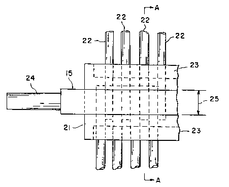
As shown in the completed assembly of Fig. 2, a preferred
embodiment of the present invention comprises a prebent U-shaped
strap 21 of a plate of metal, a standoff means 23 separating the
strands ~2 of wire from the strap 21 and ribbon explosives 15
positioned over each side of strap 21. As demonstrated in Fig.
3, the present invention further comprises a detonating means 24
such as a blasting cap mated to the two ribbon explosives 15.
An adhesive means 41 holds the ribbon explosives 15 in position
over strap 21, as illustrated in Fig. 4.
Referring to Fig. 5, the process of the present invention
begins by spreading the strands of the wires to be joined into
a flat plane. Each wire is then arranged in parallel with an
opposing wire, and each strand of each wire is alternated in
alignment to form a mesh-like arrangement, with the strands
forming an area of overlapping 50 as depicted in Fig. 5.
Complete alternate positioning of the strands, however, is not
required. This overlap 50 assures metallurgical bonding of the
multi-strand wire and creates a cross-sectional area that exceeds
the cross-sectional area of wire 22. Thus, the overlap maintains
the mechanical integrity of the wire and lowers the electrical
20~0~
resistance across the joint. Width 51 of the aligned strands may
be as small as approximately 0.04 inch and has no upper limit.
Next, a plate of metal such as copper is cut to a length
approximately equal to twice the width 51 of aligned strands plus
twice the diameter 52 of strand 22. The width of the plate must
at least be greater than the width of overlap 50 and preferably
should also be greater than the width of the ribbon explosive 15,
which is typically 0.330 inch. A width greater than the width
of the ribbon explosive will ensure a good metallurgical bond.
The plate of metal, as demonstrated in Fig. 6, is bent into
a U-shaped strap 21 such that the spacing 61 is greater than the
diameter 52 of strand 22. Referring to Fig. 2, strap 21 is then
slid over the prepositioned strands of wire. The U-shaped strap
21 eliminates the need of a coaxial arrangement of the wires and
provides an easy and simple assembly that requires minimal
training.
Referring to Fig. 4, a standoff 40 or separation between the
strap 21 and strands 22 is required to achieve the high velocity,
angular collision necessary to effect the explosive joint 10.
A standoff means 23, such as mas~ing tape or any other convenient
shim, accomplishes this necessary standoff 40 to prevent physical
contact between the strap and the strands. Minimum standoff,
approximately 0.010 inch, achieves the required velocity to
effect an explosive joint. Maximum standoff, approximately 0.025
inch, minimizes material deformation and pending energy losses.
After placement of the standoff means 23, on adhesive means
41, such as double-backed tape, is positioned and attached to the
center of strap 21 on each side as shown in Fig. 4. The adhesive
means 41 locates the ribbon explosives and provides an energy
transfer medium between the ribbon explosive and the strap. The
adhesive means 41 also protects the strap from lead embedment
generated by the ribbon explosive. ~he ribbon explosive 15 is
then cut to an appropriate length for the explosive joint 10.
Referring to Fig. 3, the appropriate length of ribbon
explosive 15 extends beyond the length of strap 21 to allow for
assembly with detonating means 24. The ribbon explosive 15 is
then centered over the adhesive means 41 and pressed onto it, as
2 Q ~t G ~
illustrated in Figs. 2 and 4, to secure a bonded position around
strap 21.
Preferably, explosive ribbons are placed on both sides of
strap 21 and initiated simultaneously to generate symmetrically
opposed forces and to minimize or eliminate offsetting forces
generated during explosion of the ribbons. An alternative
embodiment, however, would position the ribbon explosive on only
one side of strap 21 and then lay the other side of strap 21 upon
a shock absorbing means such as an anvil to maximize joining
efficiency by reducing deformations.
After positioning the ribbon explosive 15, the detonating
means 24 is mated to the ribbon explosives 15 as shown in Figs.
2 and 3. The detonation area 25 extends simultaneously across
the complete cross-section width of the ribbon explosive 15 to
attain minimum pressure and thereby cause the explosion to be
self-sustaining. The detonating means 24 initiates the ribbon
explosive 15, and firing of the explosive drives strap 21
downward and upward into the strands 22 to accomplish an
explosive joint 10.
~ lectric blasting caps containing hot bridge wires may be
used to initiate the explosive and require approximately 0.1
joule. Such blasting caps must use electrical shielding,
grounding, and fail-safe firing systems. Alternatively, a number
of aerospace approaches for initiation, such as exploding bridge
wires, mechanically actuated percussion primers, explosive
transfer lines, or lasers may serve as a detonating means 24 and
do not present as hazardous a set of conditions as electric
blasting caps.
With regard to safety, routine handling and cutting by
personnel, as well as electrical inputs, do not initiate the RDX
ribbon explosive. Alternatively, other explosive materials that
are insensitive to rifle fire and lightening, such as
dipicramide, may be used. Dipicramide is stable to 450F for 50
hours, and will burn with low energy output, but will not
detonate. Volume shielding can easily contain any explosive by-
products such as lead fragments, pressure wave, and carbon-
particle smoke. Because only small quantities of explosive are
7 20~03~9
used, the explosive pressure attenuates to less than one pound
per square inch within the first foot of distance from the
source.
The ribbon explosive 15 produces all the energy necessary
to create explosive joint 10. With the ribbon manufactured to
exacting standards, the explosive load varies less than five
percent down the length. Thus, the explosive joints vary little
once the joining parameters are established.
The wire size establishes the parameters of the joining
process. For example, a 0.025 inch wire uses a 0.030 inch plate
of copper prebent to accommodate the size of the strands of wire
and provide two 0.035 inch standoffs. The size of the ribbon
explosive is 20 grains/foot. A 0.090 inch wire also uses a 0.030
inch plate of copper prebent to accommodate wire size and two
0.035 inch standoffs. The wire size of the ribbon explosive used
in this case is 30 grains/foot. The total amount of explosive
used in the second arrangement for a 1.5 inch width splice is
less than one gram.
A particular advantage of the present invention is that the
number of wires and of strands are not limited. Another
advantage of the present invention is that the strap and the
wires can comprise the same or different metallic elements or
alloys. In other words, the strap may or may not comprise the
same material as the other wire.