Note : Les descriptions sont présentées dans la langue officielle dans laquelle elles ont été soumises.
PORTABLE TEL~PHONE
Field of the Invention
The present invention relates to a portable
telephone. In the following description, it is to be
noted that the term of portable telephone used herein also
includes a general cordless telephone.
Back~round of the Invention
An ultimate object of communication is, of course, to
enable intention or information to be transmitted or
exchanged at once anytime, from anywhere, and by anybody.
In addition to a conventional intercommunication between
fixed points, a mobile communication has been gradually
developed. The mobile communication means a communication
between a mobile body such as ship, automobile, or
airplane and a fixed point such as home or office~ and
also means an intercommunicatioD between two mobile
bodies. In recent years, a portable telephone or a
cordless telephone as a kind of means for carrying out the
mobile communication has been extensively developed.
In general, a telephone is used with a rece}ver
section put to the ear and a transmitter section Xept near
the mouth. So also in a portable telephone, it is
necessary to ensure a sufficient distance between the
receiver section and the transmitter section. ln this
~ J
-- 2
circumstance, a conventional portable telephone itself is
long and large in size to some exten-t. The portable
telephone is provided with a switch section having a
dialing function and a display section. It is known that
a protective cover for protecting the switch section only
or both the switch section and the display section is
foldably mounted to the portable telephone.
}lowever, the canventional protective cover merely has
an original function of protecting the switch section only
or both the switch section and the display section when
not using the portable telephone, and it is of little
utility value when using the portable telephone.
Summar~ of the Invention
It is therefore an object of the present invention to
provide a portable telephone which can be made
multifunctional by effectively utilizing the Protective
cover rotatably mounted to a telephone body.
In accordance with an aspect of the present
invention, there is provided a portable telephone
comprising a body including a speaker, a microphone, and
switch means; a cover r~tatably mounted to said body, said
CQVer being adapted to cover at least said switch means
when said cover is in a closed condition; cover holding
means for rotatably holding said cover with respect to
said body, said cover holding means including biasing
:
-- 3 --
means for exerting a biasing force to said cover so as to
maintain said cover at a stable position when said cover
is in an open condition; and a functional module
detachably mounted to said cover.
In accordance with another aspect of the present
invention, there is provided a portable telephone
comprising a body having a speaker, a microphone, switch
means, and a printed wiring board on which transmitting
and receivin~ circuit parts and logic circuit parts are
mounted; a functional module mounting member rotatably
mounted to said body and having a first connector; a
flexible printed wiring board for connecting said printed
wiring board to said first connector; holding means for
rotatably holding said functional module mounting member
to said body, said holding means including biasing means
for exerting a biasing force to said functional module
mounting member so as to maintain said functional module
mounting member at a stable position when said functional
module mounting member is rotated relative to said body;
and a functional module detachably mounted to said
functional module mounting member, said functional module
having a second connector adapted to engage said first
connector.
The above and other objects, features and advantages
of the present invention and the manner of realizing them
. ~ , ' ,' , . ' ', .
2 ~
- 4 -
will become more apparent, and the invention itself will
best be understood from a study of the Eollowing
description and appended claims with reference to the
a~tached drawings showing some preferred embodiments of
the invention.
Brief DescriPtion of the Drawin~s
Fig. l is a perspective view of a first preferred
embodiment of -the present invention with the protective
cover opened;
Fig. 2 is an exploded perspective view of the first
preferred embodiment;
Fig. 3 is a side view of the protective cover for
illustrating an engaging structure of an electronic
calculator module to be mounted on the protective cover;
Fig. 4 is an exploded perspective view showing the
protective cover holding mechanism in the first preferred
embodiment according to the present invention;
Fig. 5 is a vertical sectional view showing stepwise
ratational positions of the protective cover rotatably
mounted to the case;
Fig. 6 is a bottom plan view of the case shown in
Fig. 5 under the closed condition of the protective cover;
Figs. 7A, 7B and 7C are cross sections taken along
the lines A-A in Fig. 6, corresponding to cover positions
"a", "b" and "c" shown in Fig. 5;
- .
:: ,
g
- 5 --
Fig. 8 is a perspective view of a clock module to be
mounted on the protective cover;
Fig. 9 is a perspective view of a second preferred
embodiment of the prcsent invention;
Fig. 10 is an exploded perspective view of the
protective cover holding mechanism according to the second
preferred embodiment;
Fig. Il is a sectional view of a removable mounting
structure of the protective cover according to the second
preferred embodiment;
Fig. 12 is an exploded perspective view of a right-
hand portion of the removable mounting structure shown in
Fig. 11;
Fig. 13 is a cross section taken along the line A-A
in Fig. 11;
Fig. 14 is a perspective view of the protective cover
according to the second preferred embodiment with the
electronic calculator module mounted thereon;
Fig. 15 is a perspective view of the protective cover
according to the second preferred embodiment with a game
module mounted thereon;
Fig. 16 is a perspective view of a telephone stand on
which the body of the portable telephone is to be mounted;
Fig. 17 is a side view of the telephone stand with
the body of the portable telephone mounted thereon;
2 ~
-- 6 --
Fig. 1% is a perspective view of a third preferred
embodimen~ of the present invention;
Fig. 19 is a fragmentary sectional view of the third
preferred embodiment;
Fig. 20 is a perspective view of a fourth preferred
embodiment of the Present invention;
Fig. 21 is an exploded perspective view illustr~ting
a mounting mechanism for the functional module mounting
member according to the fourth preferred embodiment;
Fig. 22 is a bottom Plan view of a body case
according to the fourth preferred embodiment;
Fig. 23 is a sectional view illustrating a connecting
structure employing a flexible printed wiring board
according to the fourth preferred embodiment;
Fig. 24 is a cross sect~on taken along the line A-A
in Fig. 23; and
~ig. 25 is a fragmentary perspective view of a fifth
preferred embodiment of the present invention.
Description of the Preferred Embodiments
There will now be described a first preferred
embodiment of the present invention with reference to
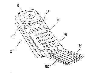
Figs. I to 7C. Referring to Fig. 1, reference numeral 2
; generally designates a body of the portable telephone
; according to the present invention. A transmitter-
receiver unit is incorporated in a case 4 of the body 2.
-- 7
The body 2 is provided with a receiver section 6
incorporating a speaXer therein, a liquid crystal display
(LCD) ~, a switch section 10 having a dialing function,
and a transmitter section ~not shown) incorporating a
microphone therein. Reference numeral 14 designates a
protective cover for the switch section 10. The
protective cover 14 is rotatably mounted to a cover
mounting projection lB of the case 4. Figs. I and 2 show
an open condition of the protective cover 14. When not
using the portable telephone, the protective cover 14 is
rotated so as to cover the switch section 10 and protect
the same.
An electronic calculator module 30 is detachably
mounted on a mounting portion 14a of the protective cover
14. As shown in Fig. 2, the electronic calculator module
30 is formed at its one end with a pair of recesses 30a,
while as shown in Fig. 3, the protective cover 14 is
formed with a pair of hooks 14b adapted to respectively
engage the recesses 30a of the module 30. The protective
cover 14 is further formed with a pawl 14c for holding the
other end of the module 30. With this arrangement, the
module 30 is mounted to the protective cover 14 so that
the former may be removed from the latter. In this
manner, by mounting the electronic calculator module 30 to
the protective cover 14, -the portable telephone can be
: :: : .
r,' ~ $~J l~
- 8 -
given a function as an electronic calculator.
~ ig. 4 is an exploded perspective view of ~he cover
holding mechanism in the irst preferred embodiment, and
it shows a condition where the body case 4 is viewed from
its back side. The case 4 is integrally formed a~ its
lower end with a cover mounting projection 1~ having a
pair of circular ho}es 20 at opposite ends thereof. The
case 4 is further formed with a pair of proiections 22
adapted to respectively engage a pair of U-shaped springs
26 which will be hereinafter described.
Reference numerals 24 denote a pair of shafts for
rotatably mounting the cover 14 to the case 4. Each shaft
24 is formed at its one end with a mounting portion 24a.
On the other hand, the cover 14 is integrallY formed with
a pair of mounting projections 28 each having a hole 29.
The mounting portions 24a of the shafts 24 are adapted to
be press-fitted with the holes 29 of the mounting
projections 28 of the cover 14. Further, each shaft 24 is
formed at its other end with a pair of annular lands 24b.
Between ~oth the annular lands 24b, there is formed an
angular plate portion 24c for stably holding the cover 14
at a predetermined inclined angle with respect to the case
4. The angular plate portions 24c of the shafts 24 are
adapted to respectively engage the U-shaped springs 2
each having a bent portion 26a at one end thereof.
.. ~ . . - .~ , .: , .
; ... , .: ~,
. ~ : ~ . : . : : . .: :
: . .: ,: .
_ 9 _
The cover 14 is mounted to the case ~ in the
following manner. First, the holes 29 of the cover 14 are
aligned to the holes 20 af the case ~, and the mounting
portions 24a of the shafts 24 are rotatably inserted
through the holes 20 of the case 4 and press-fitted into
the holes 2g of the cover 14. Then, the U-shaped springs
26 are brought into engagement with the angular plate
portions 24c of the shafts 24, and the bent portions 26a
of the U-shaped springs 26 are brought into engagement
10with the projections 22 of the case 4. Thus, the cover 14
is rotatably mounted to the case 4.
Fig. 5 shows such a ro-tatably mounted condition of
the cover 14 with respect to the case 4 in vertical
section, and Fig. 6 is a bottom plan view of Fi~. 5.
15The operation of the cover holding mechanism will now
be described with reference to Figs. 7A to 7C. ln this
preferred embodiment, a stable position of the cover 14 is
a position "b" shown in Fig. 5 where the cover 14 is
inclined at 145 with respect to the case 4. In this
stable position of the cover 14, each U-shaped spring 26
tightly contacts two opposite flat surfaces 25a of the
angular plate portion 24c of each shaft 24 as shown in
Fig. ~B. An inclined surface 25b is formed continuouslY
from one end of each flat surface 25a, so as to permit
smooth rotation of the cover 14.
: ,: .:
7 ~
- 10 -
Fig. 7A shows a closed condition of the cover l~,
which corresponds to a position '1a" shown in Fig. 5. In
this condition, the U-shaped springs 26 operate to press
the cover 14 against the case 4 through the angular plate
portions 24c of the shafts 24. Accordingly, it is not
necessary to provide a lock mechanism for maintaining a
closed condition of the cover 14, and the operability in
practical use can be improved.
Fig. 7C shows a fUllY open condition of the cover 14
obtained against a biasing force of the U-shaped springs
26, which corresponds to a position "c" shown in Fig. 5.
In this condition, the U-shaped springs 26 exert a biasing
force in a closing direction of the cover 14 through the
angular plate portions 24c of the shafts 24, so that the
cover 14 is resiliently retained. Accordingly, in an
exemplary case such that the portable telephone with the
cover 14 open is put on a flat surface such as a desk
surface under the condition where the switch section 10
faces the flat surface, and that a load is applied to the
portable telephone from the back side of the case 4, the
cover 14 is rotated to become the cundition of Fig. 7C
against the biasing force of the U-shaped springs 26, thus
obviating a possibility of breakage of the cover 14. In
this preferred embodiment, an angle defined between the
flat surface 25a of the angular plate portion 24c of each
.. . ..
., . . ` :
:: . . .: -. ; :: .
shaft 2~ and the cover 14 is set to 55 , so that the
cover 14 is stably held in open pasition inclined at
145 with respect to the case 4.
While a single stable position of the cover 14 is set
by forming the angular plate portion 24c in the vicinity
of one end of each shaft 24 in this preferred embodiment,
a plurality of stabilizer points may be set by forming a
portion of each shaft 24 in the vicinity of one end
! . ` . .
thereof into a polygonal sectional shape. In this
preferred embodiment, the stable position of the cover 14
is set in a position where the cover 14 is inclined at
145 with respect to the case 4 because an S~N
characteristic in the transmitter section becomes maximum
at this posture during the telephonic communication.
Fig. 8 shows a clock module 32. By removing the
electronic calculator module 30 from the protective cover
14 and instead mounting the clock module 32 to the
protective cover 14, the portable telephone can be given a
function as a clock. As shown in Fig. 8, the clock module
32 has an LCD 32a for displaying a time and incorporates a
buzzer 32b for sounding a time.
There is shown in Fig. 9 a second preferred
embodiment of the present invention, in which a protective
cover 14' is detachably mounted to the body 2 of the
portable telephone. A mounting mechanism for the
::
,-, ~; ; ~'''
t~ /7 7
- 12 -
protective caver 14' will now be de~cribed with reference
to Figs. 10 ta 13. The protective cover 14' is integrally
formed with a pair of maunting portions 34 and 36
respec~ively defining cavities 34a and 36a therein. In
the cavi-ty 34a of the maunting portion 34, a short shaf~
38 is maunted so as to be normally biased by a coil spring
40 in a direction such that the short shaft 38 is
partially prajected autside the cavity 34a. The shart
shaft 38 is integrally farmed with a release buttan 55 for
effecting the removal of the protective cover 14'.
On the other hand, a short shaft 42 is mounted in the
cavity 36a of the mounting portion 36 so as to be normally
biased by a coil spring 50 in a direction such that the
short shaft 42 is partially projected outside the cavity
36a. The short shaft 42 has an angular plate portion 44
and a large-diameter portion 46~ The large-diameter
port;on 46 is formed with a pair of axial grooves 46a,
while an inner wall of the cavity 36a is formed with a
pair of guide rails 48 adapted to respectively engage the
axial grooves 46a of the large-diameter portion 46. The
inner wall of the cavity 36a is further formed with a pair
of recesses 54 adapted to respectively engage a pair of
projections 52a of a stop ring 52 for preventing escape of
the short shaft 42 out of the cavity 36a. With this
arrangement, after inserting the coil spring 50 into the
:' ' ,: .
: ::
",J ~ r~
-- 13 -
cavity 36a and then inserting the short shaft 42 into the
cavity 36a, the short shaft 42 is prevented from rotating
relative to the mounting portion 36 by the engagement of
the axial grooves 46a with the guide rails 48.
Thereafter, the stop ring 52 is inserted into the cavity
36a so as ta abut against the large-diameter portion 46 of
the short shaft 42 in such a manner that the stop ring 52
is prevented from escaping out of the cavity 36a bY the
engagement of the projections 52a with the recesses 54.
Both the short shafts 38 and 42 respectively mounted
in the cavities 34a and 36a of the mounting portions 34
and 36 of the protective cover 14' are engaged with a pair
of holes 20 formed through a cover mounting projection 18
of a case 4 of the body 2, thereby rotatably mounting the
protective cover 14' to the body 2. Thereafter, as shown
in Fig. lO, a U-shaped spring 26 is engaged with the
angular plate portion 44 of the short shaft 42. With this
arrangement, when the protective cover 14' is in an open
condition with respect to the body 2, the former is held
in a stable position inclined at about 145~ with respect
to the latter similarly to the first preferred embodiment.
In the case of removing the protective cover 14' from the
body 2, the release button 55 is moved leftwardlY as
viewed in Fig. Il against the coil spring 40, so that the
protective cover 14' can be easily removed from the body
~ .. . . . .
Fig. 14 shows the protective cover 141 removed from
the body 2. The electronic calculator module 30 is
mounted on the protective cover 14' shown in Fig. 14.
Fig. 15 also shows the protective cover 14' removed from
the body 2. However, the electronic calculator module 30
is removed from the protective cover 14', and instead a
game module 56 is mounted on the protective cover 14'. By
rotatably mounting the protective cover 14' having the
game module 56 to the body 2, the portable telephone can
be given a game function.
Fig. 16 shows a telephone stand 58. The telephone
stand 58 is formed with a pair of projecting portions 58a.
A pair of short shafts 60 and 62 are mounted in the
projecting portions 58a, respectively, in such a manner as
to be normally biased by a pair of coil springs (not
shown) in opposite directions such that the short shafts
60 and 62 are partial}y projected outside the respective
proiecting portions 58a. The short shaft 60 is integrally
formed with a release button 64. After removing the
protective cover 14' from the body 2 of the portable
telephone, the body 2 is placed on the telephone stand 58
under the upright condition as shown in Fig. 17.
Telephone communication can be carried out under the
upright condition of the body 2 retained by the telephone
, . - .
, :: .'' : ' ' :' . .
: ~ , ..
3 !~ ~
stand 58 with the short shafts fiO and 62 inserted in the
holes 20 of ~he case 4 of the hody 2. The use of the
telephone stand 58 provides convenience in the case that
user's hands are fully occupied.
Fig. 18 shows a third preferred embodiment of the
present invention in perspec-tive, and Fig. 19 is a
sectional view of an essential part of the portable
telephone shown in Fig. 18. A data module 66 storing
various data such as telephone numbers is detachably
mounted on the protective cover 14. The protective cover
14 is provided with a light emitting device 68, while the
body 2 is provided with a light receiving device 70 for
receiving li~ht from the light emitting device 68. The
light emitting device 68 is operated to emit light
according to data stored in the data module 66, and the
light is received by the light receiving device 70. Thus,
the data can be optically transmitted from the data module
66 to the body 2 of the portable telephone.
In modification, the light emitting device 66 may be
provided on the body 2 and the light receiving device 70
may be provided on the protective cover 14. In this case,
a signal can be optically transmitted from the body 2 to
the protective cover 14.
Fig. 20 shows a fourth preferred embodiment of the
present invention in perspective. In this preferred
,: " ~, ~ . . ~ .,
`
- . ' , :
~: :: :, ....
3 ~l r9~
- 16 -
embodiment, a functional module mounting memher 72 is
rot~tably mounted to the cover mounting projection 18 of
the body 2 of the portable telephone. The functional
module mounting member 72 has a female connector 74. A
telephone memorandum module 76 has a male connector 82
adapted to engage the female connector 74 of the
functional module mounting member 72. The telephone
memorandum module 76 has a switch section 78 and an LCD
80. The telephone memorandum module 76 is provided with a
lock pawl 84 for locking the engagement between the female
connector 74 and the male connector 82, and is also
provided with a release button 86 integrally formed with
the lock pawl 84.
Now, a mechanism for rotatably holding the functional
module mounting member 72 in this preferred embodiment
will be described with reference to Figs. 21 to 24. The
functional module mounting member 72 is integrally formed
with a pair of mounting portions 88 and 90. The mounting
portion 88 is formed similarlY to the mounting portion 28
of the protective cover 14 shown in Fig. 4. That is, the
mounting portion 88 has a hole (not shown) for recciving
the mounting portion 24a of the shaft 24 in press-fitting
relation~hip therewith after the mounting portion 24a of
the shaft 24 is inserted through one of the holes 20 of
the cover mounting portion 18 of the case 4. The other
2 / ,~ ~ ~ 7
- 17 -
mounting portion 90 is integrally formed with a sleeve 92
adapted to rotatably engage the other hole 20 of the cover
maunting projection 18 of the case 4.
Referring to Figs. 23 and 24, a flexible printed
wiring board 94 is accommodated in the sleeve 92 and the
mounting portion 90. The flexible printed wiring board 94
is connected at its one end to the female connector 74,
and the other end is connected to a Printed wiring board
(not shown) provided in the body 2 of the portable
telephone. The functional module mounting member 72 is
rotatably mounted to the case 4 in the following manner.
That is, the sleeve 92 is first brought into rotatable
engagement with one of the holes 20 of the cover mounting
projection 18. Then, the U-shaped spring 26 is brought
into resilient engagement with the angular plate portion
24c of the shaft 24 which has been press-fitted with the
hole of the mounting portion 88. Thus, the functional
module mounting member 72 is rotatably mounted ~o the case
4. Further, when the functional module mounting member 72
is in an operative open condition, it is held in a stable
position inclined at about ~45 with respect to the case
4.
In this preferred embodiment, the female connector 74
of the functional module mounting member 72 is connected
2~ through the flexible printed wiring board 94 to the
. ~ : . :.- . . .
,:, ; , ,, ,; ~ , .
~ 9 ~
- ~8 -
printed wiring board provided in the body 2. Accordingly,
data such as telephone numbers stored in the telephone
memorandum module 76 connected to the functional module
moun~ing member 72 can be transmitted to the body 2. In
the case of removing the telephone memorandum module 76
from the functional module mounting member 72 mounted to
the body 2, the release button 86 is depressed by a user
to unlock the lock pawl 84 and accordingly release the
connection between the female connector 74 of ~he
functional module mounting member 72 and the male
connector 82 of the telephone memorandum module 76.
Fig. 25 shows an essential part of a fifth preferred
embodiment of the present invention in perspective. In
this preferred embodiment, a functional module mounting
member 72' has the male connector 82, and a telephone
memorandum module 76' has the female connector 74. In
Fig. 25, reference numerals 96 and 98 denote an LCD and a
key switch, respectively. Like the fourth preferred
embodiment, data such as telephone numbers or addresses
can be transmitted from the telephone memorandum module
76' through the connectors 74 and 82 to the body 2.
It is to be noted that the above-mentioned functional
modules such as electronic calculator module, clock
module9 game module, data module and telephone memarandum
module are merely illustrative, and that the functional
. , ,. ., ::
- 19 -
module to be employed in the present invention is not
limited to the above illustrated functional modules. For
instance, the functional module according to the present
invention may include a control mndule for externally
controlling electrical equipments in an office or home, a
personal computer communication module, a word processor
communication module, a calendar module, and a pager
module. In particular, the pager module is capable of
operating by itself for a long period of time.
Accordingly, by keeping the pager module in an an state
and the portable telephone in an off state, consumption of
a battery as a power source for the portable telephone can
be reduced.
: ~, ' : '