Sélection de la langue

Search

Sommaire du brevet 2051600 

Énoncé de désistement de responsabilité concernant l'information provenant de tiers

Une partie des informations de ce site Web a été fournie par des sources externes. Le gouvernement du Canada n'assume aucune responsabilité concernant la précision, l'actualité ou la fiabilité des informations fournies par les sources externes. Les utilisateurs qui désirent employer cette information devraient consulter directement la source des informations. Le contenu fourni par les sources externes n'est pas assujetti aux exigences sur les langues officielles, la protection des renseignements personnels et l'accessibilité.

Disponibilité de l'Abrégé et des Revendications

L'apparition de différences dans le texte et l'image des Revendications et de l'Abrégé dépend du moment auquel le document est publié. Les textes des Revendications et de l'Abrégé sont affichés :

  • lorsque la demande peut être examinée par le public;
  • lorsque le brevet est émis (délivrance).
(12) Brevet: (11) CA 2051600
(54) Titre français: BOBINE POUR L'ENROULEMENT D'ELEMENTS FILIFORMES ET AUTRES DUMEME GENRE
(54) Titre anglais: SPOOL FOR WINDING FILIFORM ELEMENTS AND THE LIKE
Statut: Périmé et au-delà du délai pour l’annulation
Données bibliographiques
(51) Classification internationale des brevets (CIB):
  • B65H 75/34 (2006.01)
  • B65H 75/18 (2006.01)
  • B65H 75/20 (2006.01)
(72) Inventeurs :
  • BARONE, MARIO (Argentine)
(73) Titulaires :
  • CONARCO ALAMBRES Y SOLDADURAS SOCIEDAD ANONIMA
(71) Demandeurs :
  • CONARCO ALAMBRES Y SOLDADURAS SOCIEDAD ANONIMA (Argentine)
(74) Agent: MARKS & CLERK
(74) Co-agent:
(45) Délivré: 1994-09-13
(22) Date de dépôt: 1991-09-17
(41) Mise à la disponibilité du public: 1992-09-22
Requête d'examen: 1993-03-08
Licence disponible: S.O.
Cédé au domaine public: S.O.
(25) Langue des documents déposés: Anglais

Traité de coopération en matière de brevets (PCT): Non

(30) Données de priorité de la demande:
Numéro de la demande Pays / territoire Date
319.295 (Argentine) 1991-03-22

Abrégés

Abrégé anglais


A spool for winding filiform elements and the
like, comprised by two parallel rings joined by means of a
plurality of U-shaped braces, including diametrally opposed
accessory elements fixed at least to some of said braces and
which, in turn, support a central nucleus allowing rotation
of the spool.

Revendications

Note : Les revendications sont présentées dans la langue officielle dans laquelle elles ont été soumises.


6
THE EMBODIMENTS OF THE INVENTION IN WHICH AN EXCLUSIVE
PROPERTY OR PRIVILEGE IS CLAIMED ARE DEFINED AS FOLLOWS:
1. Apparatus for winding filiform elements comprising a
spool and a central element for mounting the spool on a
winding support,
wherein said spool comprises first and second
generally parallel rings spaced in a longitudinal
direction, a plurality of brace means for receiving said
filiform elements, each of said brace means extending
between said first and second rings, and a plurality of
accessory means secured to selected ones of said brace
means for connecting said first and second rings to said
central element and having substantially linear, flat
bottom segments,
wherein said central element is generally
cylindrical and includes an outer surface with grooves
extending longitudinally along the length of said central
element, each of said grooves receiving a respective one
of said linear, flat bottom segments, and
wherein said central element further comprises first
and second flange means at respective opposite ends
thereof for preventing longitudinal movement of said
bottom segments in said grooves, each of said flange
means comprising a peripheral annulus extending radially
outward from said central element for engaging respective
ends of said bottom segments.
2. Apparatus according to claim 1 wherein said central
element is transversely divided into first and second
parts.
3. Apparatus according to claim 1 wherein said central
element further comprises means for engaging means for
driving said spool for winding or unwinding said filiform
elements.
4. Apparatus according to claim 3 wherein said means
for engaging comprises a projection extending radially
outward from said outer surface.

Description

Note : Les descriptions sont présentées dans la langue officielle dans laquelle elles ont été soumises.

- l 20~1600
SPOOL FOR WINDING FILIFORM ELEMENTS AND THE LIKE
FIELD OF THE lNV~I. lION
The instant invention relates to a spool for winding
filiform elements and the like, such as wires, cables, fibers,
strips and in general, any element capable of being wound.
BACRGROUND OF THE lNV~Il ION - PRIOR ART
A plurality of spools are known to the above ends,
each of which is more or less suitable for the filiform element to
be wound thereon.
As a particular example, the case of spools for the
step-wise partial delivery of the filiform element wound thereabout
are cited. This is the case, among others, of wires used for
welding.
This kind of spool is generally comprised by two
parallel rings joined by means of U-shaped abutments having flat
bottoms and located equidistantly in the circumferences determined
by said ring.
The above described structure is widely used due to
its simplicity, but has certain disadvantages which the instant
invention intends to solve. In the first place, the structure of
the prior art is weak for continuous and rough use, particularly
when unloading and re-loading the spool. Also, these operations are
cumbersome and time-consuming since the spool has no support
allowing it to be placed on a winding machine or on a dispensing
support.

~051600
-- 2
SUMMARY OF THE INVENTION
The above and other disadvantages are overcome with
the spool of the invention which comprises, as conventional spools
do, two parallel rings joined by flat-bottomed U-shaped braces,
which is characterized by having diametrically opposed accessory
elements mounted on said braces which support a central driving
nucleus.
Thus, said accessory elements improve, on one hand,
the structural rigidity of the spool, since said central nucleus
allows for the mechanical winding of filiform elements about the
spool and, subsequently it permits the mounting of the spool on a
dispensing support.
In accordance with a preferred embodiment of the
invention, said supporting elements of the central nucleus are also
shaped with a flat-bottomed U-contour connected, by its end
portions, to the arms of said diametrically opposed braces.
In turn, the flat bottom of said elements is housed
into corresponding longitudinal grooves at the nucleus periphery,
which is made preferably of synthetic resin, the shape of which
being substantially hollow and cylindrical.
In accordance with a most preferred embodiment of the
invention, said nucleus is transversely divided into two equal
portions such that, once the supporting elements are mounted, the
corresponding longitudinal grooves at the periphery of said portions
may be made to slide from both sides of the spool along the flat

2051600
-- 3
bottom of the supporting elements until they abut. It is obvious
that this alternative greatly facilitates the construction of the
assembly.
Another aspect of this invention is as follows:
Apparatus for winding filiform elements comprising a spool and
a central element for mounting the spool on a winding support,
wherein said spool comprises first and second generally parallel
rings spaced in a longitudinal direction, a plurality of brace means
for receiving said filiform elements, each of said brace means
extending between said first and second rings, and a plurality of
accessory means secured to selected ones of said brace means for
connecting said first and second rings to said central element and
having substantially linear, flat bottom segments, wherein said
central element is generally cylindrical and includes an outer
surface with grooves extending longitudinally along the length of
said central element, each of said grooves receiving a respective
one of said linear, flat bottom segments, and wherein said central
element further comprises first and second flange means at
respective opposite ends thereof for preventing longitudinal
movement of said bottom segments in said grooves, each of said
flange means comprising a peripheral annulus extending radially
outward from said central element for engaging respective ends of
said bottom segments.

~ 4 ~ 20 5 1 60 0
BRIEF DESCRIPTION OF THE DRAWINGS
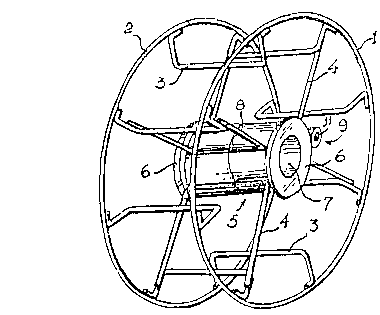
Figure 1 is a perspective view of the spool;
Figure 2 is an elevational section thereof;
Figure 3 is a cross section of the nucleus;
Figure 4 is a partial elevational section of the
spool assembled; and
Figure 5 is an exploded elevational section of
the spool.
In all figures the same reference numerals indicate
the same or corresponding parts.
DETAILED DESCRIPTION OF THE lNV~N~ ION
The spool is comprised by parallel rings 1 and 2
supported by a plurality of equidistant braces 3 as per an even
number of units, such that each brace corresponds to a diametrically
opposed counterpart.
At certain pairs of opposed braces 3 corresponding
flat-bottomed U-shaped elements 4 are mounted, such that the ends of
their arms are fixed to the arms of the corresponding brace 3 and
their opposite flat bottoms are spaced apart a determined distance.
The central space between said flat bottoms is
occupied by a substantially cylindrical nucleus 5 which, as may be
seen in figures 1 to 3, has at its ends corresponding peripheral
flanges 6 and an axial hole 7. The body of the cylindrical nucleus
5 has a plurality of diametrically opposed grooves determined by
~'

2051600
-- 5
corresponding longitudinal ribs 8 provided in pairs and spaced apart
a distance equal to the thickness of elements 4 and into which the
flat bottoms thereof are housed.
Further, nucleus 5 has an external longitudinal
shoulder 9 formed by a longitudinal projection 10, the edge of which
is shaped as a hollow cylinder 11, which radially extends over
flanges 6 of the nucleus. This projection is precisely the element
for engaging a drive means (not shown) and allowing the mechanical
loading of the spool in suitable machines.
In accordance with the embodiment disclosed, nucleus
5 is transversely divided in two equal portions, as may be seen in
Figures 1, 4 and 5. In figure 5 the nucleus is shown before being
mounted on the spool. The mounting is carried out by sliding the
flat bottoms of elements 4 along the grooves determined by ribs 8
until, due to the size of the nucleus flanges 6 contact the arms
of elements 4, while both portions of the nucleus abut.
Obviously, when the nucleus 5 is formed as a unit,
the mounting procedure will be the reverse, i.e., the bases of
elements 4 are seated on the grooves determined by ribs 8 and then
the ends of the arms of said elements 4 are fixed to braces 3 by
means, for example, of welding or a similar resource.
r~

Dessin représentatif
Une figure unique qui représente un dessin illustrant l'invention.
États administratifs

2024-08-01 : Dans le cadre de la transition vers les Brevets de nouvelle génération (BNG), la base de données sur les brevets canadiens (BDBC) contient désormais un Historique d'événement plus détaillé, qui reproduit le Journal des événements de notre nouvelle solution interne.

Veuillez noter que les événements débutant par « Inactive : » se réfèrent à des événements qui ne sont plus utilisés dans notre nouvelle solution interne.

Pour une meilleure compréhension de l'état de la demande ou brevet qui figure sur cette page, la rubrique Mise en garde , et les descriptions de Brevet , Historique d'événement , Taxes périodiques et Historique des paiements devraient être consultées.

Historique d'événement

Description Date
Inactive : CIB de MCD 2006-03-11
Le délai pour l'annulation est expiré 1998-09-17
Lettre envoyée 1997-09-17
Accordé par délivrance 1994-09-13
Exigences pour une requête d'examen - jugée conforme 1993-03-08
Toutes les exigences pour l'examen - jugée conforme 1993-03-08
Demande publiée (accessible au public) 1992-09-22

Historique d'abandonnement

Il n'y a pas d'historique d'abandonnement

Titulaires au dossier

Les titulaires actuels et antérieures au dossier sont affichés en ordre alphabétique.

Titulaires actuels au dossier
CONARCO ALAMBRES Y SOLDADURAS SOCIEDAD ANONIMA
Titulaires antérieures au dossier
MARIO BARONE
Les propriétaires antérieurs qui ne figurent pas dans la liste des « Propriétaires au dossier » apparaîtront dans d'autres documents au dossier.
Documents

Pour visionner les fichiers sélectionnés, entrer le code reCAPTCHA :


Pour visualiser une image, cliquer sur un lien dans la colonne description du document. Pour télécharger l'image (les images), cliquer l'une ou plusieurs cases à cocher dans la première colonne et ensuite cliquer sur le bouton "Télécharger sélection en format PDF (archive Zip)" ou le bouton "Télécharger sélection (en un fichier PDF fusionné)".

Liste des documents de brevet publiés et non publiés sur la BDBC .

Si vous avez des difficultés à accéder au contenu, veuillez communiquer avec le Centre de services à la clientèle au 1-866-997-1936, ou envoyer un courriel au Centre de service à la clientèle de l'OPIC.


Description du
Document 
Date
(aaaa-mm-jj) 
Nombre de pages   Taille de l'image (Ko) 
Page couverture 1996-02-13 1 17
Description 1994-09-13 5 173
Abrégé 1994-09-13 1 9
Revendications 1994-09-13 1 47
Page couverture 1993-12-10 1 12
Revendications 1993-12-10 1 40
Abrégé 1993-12-10 1 8
Dessins 1993-12-10 3 52
Description 1993-12-10 5 147
Dessins 1994-09-13 3 60
Dessin représentatif 1999-06-30 1 15
Avis concernant la taxe de maintien 1997-10-15 1 178
Taxes 1996-07-31 1 40
Taxes 1995-09-12 1 43
Taxes 1994-09-09 1 41
Taxes 1993-09-17 1 31
Courtoisie - Lettre du bureau 1993-05-17 1 50
Correspondance reliée au PCT 1994-06-20 1 46
Correspondance de la poursuite 1993-03-09 1 29
Correspondance de la poursuite 1993-06-29 2 56