Sélection de la langue

Search

Sommaire du brevet 2052120 

Énoncé de désistement de responsabilité concernant l'information provenant de tiers

Une partie des informations de ce site Web a été fournie par des sources externes. Le gouvernement du Canada n'assume aucune responsabilité concernant la précision, l'actualité ou la fiabilité des informations fournies par les sources externes. Les utilisateurs qui désirent employer cette information devraient consulter directement la source des informations. Le contenu fourni par les sources externes n'est pas assujetti aux exigences sur les langues officielles, la protection des renseignements personnels et l'accessibilité.

Disponibilité de l'Abrégé et des Revendications

L'apparition de différences dans le texte et l'image des Revendications et de l'Abrégé dépend du moment auquel le document est publié. Les textes des Revendications et de l'Abrégé sont affichés :

  • lorsque la demande peut être examinée par le public;
  • lorsque le brevet est émis (délivrance).
(12) Brevet: (11) CA 2052120
(54) Titre français: CAPTEUR D'EFFORT DE TRACTION A AXE DE FLEXION
(54) Titre anglais: BENDING SHAFT DRAFT FORCE SENSOR
Statut: Périmé et au-delà du délai pour l’annulation
Données bibliographiques
(51) Classification internationale des brevets (CIB):
  • G01L 01/00 (2006.01)
  • A01B 63/112 (2006.01)
  • G01L 05/13 (2006.01)
(72) Inventeurs :
  • VANGERPEN, HARLAN WELBERT (Etats-Unis d'Amérique)
(73) Titulaires :
  • DEERE & COMPANY
(71) Demandeurs :
  • DEERE & COMPANY (Etats-Unis d'Amérique)
(74) Agent: BORDEN LADNER GERVAIS LLP
(74) Co-agent:
(45) Délivré: 1996-06-04
(22) Date de dépôt: 1991-09-24
(41) Mise à la disponibilité du public: 1992-05-14
Requête d'examen: 1991-09-24
Licence disponible: S.O.
Cédé au domaine public: S.O.
(25) Langue des documents déposés: Anglais

Traité de coopération en matière de brevets (PCT): Non

(30) Données de priorité de la demande:
Numéro de la demande Pays / territoire Date
611,628 (Etats-Unis d'Amérique) 1990-11-13

Abrégés

Abrégé anglais


A draft force sensor includes a bendable shaft which
extends laterally though a pair of spaced apart supports.
Draft links are coupled to the ends of the shaft. A curved
flexible strap is positioned between the supports and has its
ends coupled to the shaft by adjustable support brackets. In
a no-load condition the strap is concave in a direction facing
the shaft. A displacement transducer, such as a rectilinear
potentiometer, linear variable transformer or other electrical
device which is sensitive to displacement, is mounted between
the shaft and the central portion of the strap. The
displacement transducer senses the change of distance from the
shaft to the "arch" of the strap and generates an electrical
signal indicative of the forces on the shaft. The load from
the draft links is applied to the ends of the shaft, causing
it to bend and causing the strap to flex in the opposite
direction. Thus, the shaft and strap act as a mechanical
amplifier. The resulting draft sensor can sense both tension
and compression.

Revendications

Note : Les revendications sont présentées dans la langue officielle dans laquelle elles ont été soumises.


THE EMBODIMENTS OF THE INVENTION IN WHICH AN EXCLUSIVE PROPERTY OR PRIVILEGE
IS CLAIMED ARE DEFINED AS FOLLOWS:
1. In a vehicle draft control system, a force sensor
for sensing forces applied to a pair of laterally spaced
apart draft links connected to the vehicle, the force sensor
comprising:
a pair of laterally spaced apart support members fixed to
a frame of the vehicle;
a shaft extending laterally between the support members,
each end of the shaft projecting laterally beyond a
corresponding one of the supports;
means for coupling one of the draft links to each end of
the shaft;
a strap located between the supports and having a first
end attached to a part of the shaft adjacent to one of the
supports and a second end attached to a part of the shaft
adjacent to the other of the supports, the strap being
substantially more flexible than the shaft and having a
central portion which moves towards and away from the shaft as
the shaft bends, and the strap being curved in a no-load
condition; and
a displacement transducer for sensing changes in
separation between the shaft and the central portion of the
strap as the shaft bends in response to forces transmitted to
it from the draft links.
2. The draft sensor of claim 1, wherein:
a spherical bushing is mounted in one of the supports and
receives a first part of the shaft, said spherical bushing
permitting the first part of the shaft to pivot in the first
support as the shaft bends; and
a cross pin couples the second part of the shaft to the
other support and prevents the shaft from being withdrawn from
the supports.
3. The draft sensor of claim 2, wherein:
an axis of the cross pin extends substantially
perpendicular to a bending plane of the shaft.
4. The draft sensor of claim 1, wherein:

the strap is concave in a direction facing the shaft.
The draft sensor of claim 1, wherein:
at least one end of the strap is attached to a support
bracket which is mounted to the shaft, the support bracket
including adjusting means for adjusting the position of said
at least one end of the strap with respect to the shaft.
6. The draft sensor of claim 1, further comprising:
a support bracket having a body with slot therein for
receiving one end of the strap and a pair of legs extending
from the body;
means for coupling the legs to the shaft; and
adjusting means for adjusting the position of said one
end of the strap with respect to the shaft.
7. In a vehicle draft control system, a force sensor
for sensing forces applied to a pair of laterally spaced
apart draft links connected to the vehicle, the force sensor
comprising a laterally extending bendable shaft with ends
coupled to the draft links and means for sensing bending of
the shaft in response to forces transmitted to the shaft by
the draft links, characterized by:
a strap having laterally spaced apart ends attached to
the shaft, the strap being substantially more flexible than
the shaft and having a central portion which moves towards and
away from the shaft as the shaft bends, and the strap being
curved in a no-load condition; and
a displacement transducer for sensing changes in
separation between the shaft and the central portion of the
strap as the shaft bends in response to forces transmitted to
it from the draft links.

Description

Note : Les descriptions sont présentées dans la langue officielle dans laquelle elles ont été soumises.

, /- 2~ 0
BENDING SHAFT DRAFT FORCE SENSOR
Background of Invention
The present invention relates to a force sensor for
sensing forces, such as the draft forces applied to the
implement hitch of an agricultural tractor.
To provide draft control for agricultural tractors a
means of measuring the draft force is required. Known draft
force measuring mechanisms for tractor draft control systems
are described in U.S. Patent No. 2,864,295, issued to Du
Shane, in 1958, in U.S. Patent No. 2,974,733, issued to
Fletcher in 1961 and in U.S. Patent No. 3,022,831, issued to
Hess in 1962. In these known designs the draft force is
applied to opposite ends of a bending shaft which is supported
by laterally spaced apart supports. A linkage transmits the
deflection of the central part of the shaft to a servo
mechanism of the tractor hitch control system. However, in
such designs the sensing sensitivity was limited by the
stiffness and the resulting small amount of flexing of the
bending shaft. Accordingly, a relatively simple, inexpensive
and sensitive bending shaft type draft force sensing mechanism
is desired.
Summary of Invention
One object of the present invention is to provide a
simple, inexpensive and sensitive bending shaft type draft
force sensor for an electronic draft control system.
Another object of the present invention is to provide
such a sensor which utilizes a commercially available
displacement transducer.
These and other objects are achieved by the present
invention wherein a draft force sensor includes a bendable
shaft which extends laterally though a pair of spaced apart
supports. A draft link is coupled to each end of the shaft.
A flexible strap is positioned between the supports and has
its ends attached to the shaft at positions near the supports.
In a no-load condition, the strap is curved and is concave in
a direction facing the shaft. A displacement transducer, such
as a rectilinear potentiometer, linear variable transformer or
~k

J O
other electrical device which is sensitive to displacement, is
mounted between the shaft and the central portion of the
strap. The displacement transducer senses the change of
distance from the shaft to the "arch" of the strap and
5 generates an electrical signal indicative of the forces on the
shaft. The load from the draft links is applied to the ends
of the shaft, causing it to bend and causing the strap to flex
in the opposite direction. Thus, the shaft and strap act as a
mechanical amplifier. The resulting draft sensor can sense
both tension and compression in the draft links.
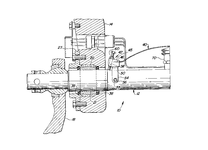
Brief Description of the Drawinqs
Figures la and lb are views in the downward direction of
left and right hand portions of a tractor bending shaft draft
force sensor constructed according to the present invention;
Figure 2 is a sectional view along line 2-2 of Fig. lb;
Figure 3 is an isometric view of one embodiment of a
flexible strap support bracket of the present invention;
Figure 4 is an isometric view of another embodiment of a
flexible strap support bracket of the present invention;
Detailed Description
The draft sensor 10 includes a draft shaft or bendable
shaft 12 which extends laterally through supports 14 and 16
which are formed by a frame or housing portion of the tractor
to the rear of the rear axle housing (not shown). The forward
ends of draft links 18,20 are coupled to opposite ends of the
shaft 12 which extend laterally out from the supports 14,16.
Support 14 supports an enlarged diameter portion 21 of the
shaft 12 via a spherical bearing or bushing 22 which is
retained in the support 14 by clamp 23. This spherical
bushing 22 allows the shaft 12 to change its angular position
when the pull of the draft links 18,20 tends to bend the shaft
12.

2~21~0
Bearing 16 loosely receives and supports an enlarged
diameter portion 24 of the shaft 12. Enlarged diameter
portion 24 has a pair of rounded cylindrical surfaces 26 and
27 separated by upper and lower horizontally extending flat
surfaces 28 and 29. A cross pin 30 extends vertically through
a bore 32 in portion 24 and the ends of pins 30 are contained
in bushings 34,36 which are lined with a low friction
material, such as "teflon" to operate with no lubrication.
The bushings 34,36 at each end of the pin 30 are pressed into
bores in the support 16. Ring seals 38 are mounted on both
sides of both bushings 22 and 24 to protect them from
contaminants.
A strap 40 has opposite ends which are anchored by strap
supports 42 which are attached to the shaft 12 adjacent to and
inside the supports 14,16. The strap 40 is substantially
thinner, and thus more flexible than the shaft 12. When no
force is applied to it, the strap 40 has a curved shape and it
is concave in a direction facing the shaft 12.
Each strap support 42 has a body 45 with a slot 46 into
which is inserted an end of the strap 40. A pair of legs 50
extend from each body 45 and grip the shaft 12. As best seen
in Figs. 1 and 3, the legs 50 may have apertured end portions
54 which are coupled to the shaft 12 by means of bolts or pins
55 which extend through mounting holes 56 which extend through
the shaft 12. An alternate strap support 42', as best seen in
Fig. 4, has legs 50' which have bent end portions or feet 54'
which are received in shallow mounting recesses 56'in the
shaft 12. In both strap support designs a threaded bore 58
extends through each body 45 at a small angle with respect to
a plane which contains the center line of the legs 50. An
adjustment bolt or capscrew 60 is installed in each bore 58
with an end engaging the shaft 12 so that the position of the
body 45 and thus the ends of the strap 40 can be adjusted by
turning the capscrew 60.
A low cost commercially available displacement transducer
70 is positioned between the shaft 12 and the central part of
the strap 40. The transducer 70 may be a rectilinear

2~52120
potentiometer, a linear variable transformer or other
electrical device which is sensitive to displacement. The
draft forces transmitted to the ends of the shaft 12 by the
links 18,20 will bend the shaft 12 and the flexible strap 22
will act as a mechanical amplifier. Manufacturing tolerances
may result in the transducer 70 not having the right voltage
output for a zero amount of draft force. Therefore, after the
transducer 70 is installed the capscrews 60 are adjusted so
that the transducer 70 provides an electrical "zero" output
signal.
As tension is applied to the draft links 18,20 tending to
pull the ends of the shaft 12 downwards viewing Fig 1, the
central part of the shaft 12 bends upwards. The strap support
brackets 42 and the ends of the strap 40 move apart so that
the center of the strap 40 moves closer to the center of the
shaft 12. This changes the voltage output from transducer 70.
This voltage signal may be applied to an input of an
electronic hitch or implement control system.
Because pin 30 extends vertically, it permits pivotal
bending of the shaft 12 in a horizontal plane. The pin 30
prevents the shaft 12 from rotating about its axis as the
draft links 18,20 are raised and lowered and also prevents the
shaft 12 from moving axially and exiting endwise from the
supports 14,16. Pin 30 also absorbs the lateral loads applied
to the shaft 12 as the draft links absorb side loads.
The pin 30 is a loose fit within the bore 32. When the
shaft 12 bends, the pin 30 will roll within the bushings
34,36. This rolling takes place because there is much less
friction between the load surfaces of the bushings 34,36 on
the ends of the pin 30 than between the steel on steel contact
of the pin 30 with the inner surface of bore 32. The
looseness which permits rolling of the pin 30 also allows the
pin to deflect due to vertical loads without the pin bottoming
out until a large deflection occurs.
While the invention has been described in conjunction
with a specific embodiment, it is to be understood that many
alternatives, modifications, and variations will be apparent

20~212~
to those skilled in the art in light of the foregoing
description. Accordingly, this invention is intended to
embrace all such alternatives, modifications, and variations
which fall within the spirit and scope of the appending
claims.

Dessin représentatif
Une figure unique qui représente un dessin illustrant l'invention.
États administratifs

2024-08-01 : Dans le cadre de la transition vers les Brevets de nouvelle génération (BNG), la base de données sur les brevets canadiens (BDBC) contient désormais un Historique d'événement plus détaillé, qui reproduit le Journal des événements de notre nouvelle solution interne.

Veuillez noter que les événements débutant par « Inactive : » se réfèrent à des événements qui ne sont plus utilisés dans notre nouvelle solution interne.

Pour une meilleure compréhension de l'état de la demande ou brevet qui figure sur cette page, la rubrique Mise en garde , et les descriptions de Brevet , Historique d'événement , Taxes périodiques et Historique des paiements devraient être consultées.

Historique d'événement

Description Date
Inactive : CIB de MCD 2006-03-11
Le délai pour l'annulation est expiré 2002-09-24
Lettre envoyée 2001-09-24
Accordé par délivrance 1996-06-04
Demande publiée (accessible au public) 1992-05-14
Toutes les exigences pour l'examen - jugée conforme 1991-09-24
Exigences pour une requête d'examen - jugée conforme 1991-09-24

Historique d'abandonnement

Il n'y a pas d'historique d'abandonnement

Historique des taxes

Type de taxes Anniversaire Échéance Date payée
TM (brevet, 6e anniv.) - générale 1997-09-24 1997-09-23
TM (brevet, 7e anniv.) - générale 1998-09-24 1998-09-23
TM (brevet, 8e anniv.) - générale 1999-09-24 1999-09-22
TM (brevet, 9e anniv.) - générale 2000-09-25 2000-09-22
Titulaires au dossier

Les titulaires actuels et antérieures au dossier sont affichés en ordre alphabétique.

Titulaires actuels au dossier
DEERE & COMPANY
Titulaires antérieures au dossier
HARLAN WELBERT VANGERPEN
Les propriétaires antérieurs qui ne figurent pas dans la liste des « Propriétaires au dossier » apparaîtront dans d'autres documents au dossier.
Documents

Pour visionner les fichiers sélectionnés, entrer le code reCAPTCHA :


Pour visualiser une image, cliquer sur un lien dans la colonne description du document. Pour télécharger l'image (les images), cliquer l'une ou plusieurs cases à cocher dans la première colonne et ensuite cliquer sur le bouton "Télécharger sélection en format PDF (archive Zip)" ou le bouton "Télécharger sélection (en un fichier PDF fusionné)".

Liste des documents de brevet publiés et non publiés sur la BDBC .

Si vous avez des difficultés à accéder au contenu, veuillez communiquer avec le Centre de services à la clientèle au 1-866-997-1936, ou envoyer un courriel au Centre de service à la clientèle de l'OPIC.


Description du
Document 
Date
(aaaa-mm-jj) 
Nombre de pages   Taille de l'image (Ko) 
Revendications 1994-03-26 2 90
Dessins 1994-03-26 4 160
Abrégé 1994-03-26 1 31
Description 1994-03-26 5 219
Description 1996-06-03 5 212
Abrégé 1996-06-03 1 30
Revendications 1996-06-03 2 86
Dessins 1996-06-03 4 128
Dessin représentatif 1999-07-04 1 35
Avis concernant la taxe de maintien 2001-10-21 1 178
Taxes 1996-09-22 1 43
Taxes 1995-09-21 1 41
Taxes 1994-09-22 1 69
Taxes 1993-09-22 1 46
Correspondance 1996-03-27 1 29
Correspondance 1992-05-03 1 28