Note : Les descriptions sont présentées dans la langue officielle dans laquelle elles ont été soumises.
~C~5;~5~
BACKGROUND OF THE INVENTION
2 1. Field of the Invention
3 This invention relates broadly to gravity backwash filters and gravity
4 filtering and backwashing methods. More particularly, it concerns so-called
variable declining rate filtration systems and methods.
6 2. Description of the Prior Art
7 Granular media filters used for the removal of suspended material
8 from water, wastewater, or other fluids have been operated in many modes
g such as constant pressure, constant rate, constant level, influent flow
splitting and variable declining rate filtration (VDRF). Of these, VDRF
offers desirable advantages (see the EPA technology transfer seminar
2 publication entitled "Wastewater Filtration Design Considerations" of July13 1974, pages 28 - 32). The present invention provides im~lovelllents in
4 VDRF apparatus and methods.
1 5 The construction of VDRF filters has taken many forms, the majority
16 of which use valves to control flows during the filtering and backwashing
17 cycles. However, the use of siphons is advantageous because of their
18 simpler mechanical construction and reliability.
19 Filter apparatus using siphons for flow control is described in U.S.
patents 3,134,735; 3,282,432; 3,312,348 and 4,122,013. However, in such
21 apparatus, only influent flow splitting operation is possible limiting the2 2 usefulness thereof. A different application of siphons having several unique
2 3 features in accordance with the present invention retains the advantages of
2 4 siphons and allows the use of VDRF operation.
The aforesaid EPA publication on page 30, shows the conventional
2 6 configuration for the VDRF type filter in which the effluent discharge level
27 control weir is below the wash trough necessitating the use of a backwash
28 supply under ~ures~ule, usually a pumped supply. However, it is known to
2 9 have an effluent weir above the wash trough thereby providing without use
of pumps the necessary pressure for backwashing (see U.S. 3,771,655 and
3 1 4,537,687). The present invention uses this type of wash pressure in
3 2 providing new advancements in the filtering art.
3 3 Another problem encountered with declining rate filters is the need
3 4 to restrict the influent flow rate to the design maximum of the filter during
3 5 periods of low media headloss following a backwash. In the past, this has
36 been attained by (a) use of a single inlet siphon equipped with flow
3 7 restricting means, (b) flow restricting means at the outlet of the filter basin
_"
.~
26~5~5~
or (c) a parti~ ing control on a single influent siphon. The present
2 invention provides new, improved means for restricting influent flow rate in
3 declining rate filters during periods of their operation under low media4 headloss.
OBJECTS
6 A principal object of the invention is the provision of hllpluvell-ents
7 in variable declining rate filtration (VDRF) systems and methods.
8 Further objects include the provision of:
g 1. New ill.~luvelllents in the use of syphons for intermittent
restriction of influent flow in open gravity, VDRF filters.
11 2. Such filters and related filtration methods that do not require
12 use of pumps to provide pressure necessary for backwashing.
13 3. Illlplovements in VDRF systems and methods that eliminate
4 the need for influent flow restriction devices, e.g., valve or orifice plate, to
limit m~i.llull. flow rate.
16 Other objects and further scope of applicability of the present
17 invention will become apparent from the detailed descriptions given herein;
18 it should be understood, however, that the detailed descriptions, while
19 indicating preferred embodiments of the invention, are given by way of
illustration only, since various changes and modifications within the spirit
21 and scope of the invention will become apparent from such descriptions.
22 SUMMARY OF THE INVENTION
23 The objects are accomplished, in part, in accordance with the
24 invention by the provision of a declining rate filter system including afilter cell containing a bed of particulate filter media defined by an upper
26 bed elevation and a lower bed elevation, an underdrain below the lower bed
27 elevation, effluent means that communicates with the underdrain to
28 discharge effluent from the system at a discharge elevation above the upper
29 bed elevation, flume means positioned at an input elevation above the
discharge elevation carrying a stream of influent, a backwash siphon to
31 discharge backwash water from the system, vacuum means and valve means
32 for applying vacuum to siphons of the system from the vacuum means or for
33 opening the siphons to ambient.
34 The i.. pruved filter system comprises first and second influent
35 siphons, both arranged to conduit influent from the flume means directly
36 into the filter cell. The first influent siphon is defined by a first inlet end
37 positioned within the stream of influent, a first outlet end positioned at a
2~5~5~
first outlet elevation below the discharge elevation and a first intermediate
2 section that joins the first inlet end to the first outlet end. The first
3 intermediate section includes a portion that rises to an upper elevation
4 above the first inlet end.
The second influent siphon is defined by a structure like the first
6 influent siphon except that its ma~il.lulll fluid handling capacity is
7 substantially greater than the m~ llum fluid handling capacity of the first
8 influent siphon at equivalent pressure differentials because the effective
g lllhlilllulll cross-sectional area of the second siphon is substantially greater
than that of the first siphon.
Conduit means connects the first and second intermediate section
12 portions of the first and second siphons to the vacuum and valve means.13 The objects of the invention are further accomplished by the
14 provision of new methods of conducting declining rate filtration by flowing a
stream of influent to be filtered to a conrilling station of a filtration site that
16 includes a filter bed of particulate filter media, siphoning influent from the
17 conrillillg station to the filter bed after backwashing of the filter media
18 through a first siphon and thereafter as headloss in the filter bed increases,
19 siphoning influent from the conrillillg station to the filter bed through a
2 o second siphon that has an effective lnillilllulll cross-sectional area
21 substantially greater than that of the first siphon.
2 2 BRIEF DESCRIPTION OF THE DRAWINGS
2 3 A more complete understanding of the invention can be obtained by
2 4 referellce to the accompanying drawings in which:
2 5 FIG. 1 is a lateral, sectional view of a declining rate filter system in
2 6 accordance with the invention operating in the filter.
2 7 FIG. 2 is a plan view, partially in section, of the filter system of FIG.
28 1.
29 FIG. 3 is a lateral, sectional view similar to FIG. 1 showing initial
3 o filtration operation in all cells.
31 FIG. 4 is a lateral, sectional view similar to FIG. 1 showing filtration
3 2 operation with m~hllulll head loss in the right-hand cell.
3 3 FIG. 5 is a lateral, sectional view similar to FIG. 1 showing drain in
34 the right-hand cell and filtration operation in the remzlining cells of the
3 5 system.
3 6 FIG. 6 is a lateral, sectional view similar to FIG. 1 showing
37 backwashing in the right-hand cell and filtration operation in the rem~ining
2~5
cells of the system.
2 DESCRIPTION OF THE PREFERRED EMBODIMENTS
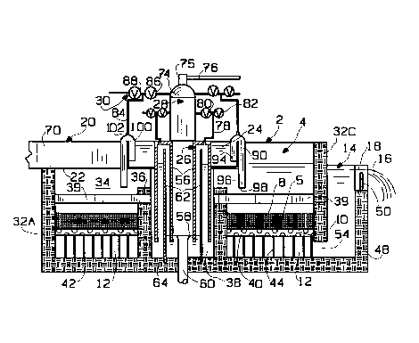
3 Referring in detail to the drawings, the declining rate filter system 2
4 includes four filter cells 4 containing beds 5 of particulate filter media 6
defined by an upper bed elevation 8 and a lower bed elevation 10.
6 Underdrains 12 conll,lunicate with effluent means 14 to discharge effluent7 16 from the system 2 at a discharge elevation 18 above the upper bed
8 elevations 8.
g System 2 further includes flume means 20 positioned at an input
0 elevation 22 above the discharge elevation 18 to carry a stream of influent
11 24, backwash siphons 26 to discharge backwash water from system 2,
12 vacuum means 28 and valve means 30 for applying vacuum to system
3 siphons from the vacuum means 28 or for opening the siphons to ambient.
4 The cells 4 are defined by outside walls 32A, 32B, 32C and 32D plus
inside walls 34. Forebay walls 36 within the cells 4 separate the forebays 38
16 from the filter beds 5. Wash troughs 39 extend through the walls 36 to
17 convey wash water from above the beds 5 into the forebays 38.
18 The filter media 6 are supported on porous webs 40 which, in turn,
19 are supported above the cell floor 42 by spacers 44.
The effluent means 14 includes side walls 46, end wall 48, weir 50
2 1 positioned in end wall slot 52 and inlet opening 54 formed in the bottom of
22 cell wall 32C. The effluent means may be designed in any shape or
2 3 volumetric capacity. The weir 50 is advantageously con~ll ucted so that its
2 4 height can be varied to raise or lower the discharge elevation 18.
The backwash siphons 26 conl~lise inverted columnar members 56,
2 6 whose lower ends 58 extend below the upper extension of funnel drain 60,
2 7 and inner walls 62 that have their lower ends 64 grouted into slots in the cell
28 floor 42. The siphons 26 are supported by an annular core 66 which is
2 9 grouted to the inner ends 68 of the inside walls 34.
3 o Flume means 20 COm,')l ises influent flume 70 and annular distribution
3 1 channel 72, both supported by suitable cut-out portions in the inside walls 34
3 2 and in outside wall 32A.
33 The vacuum means 28 colll~lises a vacuum tank 74 connected via
3 4 nipple 75 and pipe 76 to a vacuum pump (not shown).
3 5 Value means 30 colll~lises first siphon pipes 78, suction valves 80 and
3 6 exhaust valves 82 plus second siphon pipes 84, suction valves 86 and exhaust
3 7 valves 88.
21~5215~
Each filter cell 4 of the il~ uved filter system 2 is provided with a
2 first influent siphon 90 and a second influent siphon 92, both arranged to
3 conduit influent 24 from the flume means 20 into respective filter cells 4.
4 The first influent siphons 90 are defined by a first inlet end 94 positioned
within the stream of influent 24, a first outlet end 96 positioned at a first
6 outlet elevation 98 below the discharge elevation 18 and a first intermediate
7 section 100 that joins the first inlet end 94 to the first outlet end 96. Each
8 first intermediate section 100 includes a portion that rises to an upper
9 elevation above the first inlet end 94 and carries a nipple 102 by which the
siphons 90 are connected to siphon pipes 84.
The second influent siphons 92 are defined by a structure like the
first influent siphons 90 except that their ma~ill,ull, fluid handling capacity is
3 substantially greater than the m~ximulll fluid handling capacity of the first
14 influent siphon at equivalent pressure dirrerelllials because the effective
lllinilllum cross-sectional area of the second siphons 92 are substantially
16 greater than that of the first siphons 90.
17 Initial filtration operation of the VDRF system 2 is illustrated in FIG.
18 3 with the water level 104 in all cells being substantially the same and slightly
19 higher than discharge elevation 18. To reach this point, water is introduced
into the cells until they fill enough to cover the outlet ends 96 of the influent
21 siphons 90 & 92. This can be accomplished in various ways, e.g., by slots
22 (not shown) in the top edge of the annular distribution channel 72 to let
23 influent 24 flow into the cells 4. With their outlet end immersed in water,
2 4 the siphons 90 & 92 can a activated.
Since the headlosses in all cells 4 at this point are at a lllinilllulll, only
26 siphons 90 in all cells 4 are actuated by opening valves 86, with valves 88
27 closed, so that water rises in the siphons 90 until they are completely filled.
2 8 Siphoning action in the siphons 90 begins so cells 4 are charged with influent
2 9 24 passing through the siphons from channel 72. The effective cross-section
of the siphons 90 are designed to deliver influent at such rate that the
31 influent level 104 in the cells and level 106 in the forebays 38 will be only
32 slightly above the discharge elevation 18 when the headloss in the cells 4 is at
33 a lllinilllulll as shown in FIG. 3. (The liquid level 104 in the left-hand cell 4 is
3 4 not shown because of the presence of flume 70.)
As filtration continues, accumulation of solids in the filter media 6
36 will cause the headloss in the filter beds 5 to increase, usually with such
37 increase varying in the different cells 4. As this occurs, the liquid levels 104,
2~ 5~L
106 and 108 will rise.
2 At an a~plo~liate time for each different cell 4, siphon 92 for a cell
3 will be activated by opening valve 86 associated with such cell, with its valve
4 88 closed so that water rises in such siphon until it is completely filled. At
the same time, siphon 90 for that cell is deactivated by opening its siphon's
6 valve 88. The larger capacity siphon 92 delivers more influent into its cell 4
7 at lower ~res~,ure loss than siphon 90. Siphon 92 continues to operate as
8 liquid levels 104 and 108 become closer thus reducing influent flow as
g required in declining rate operation. When flow through siphon 92 is
0 essentially zero, backwashing of the associated cell is initiated.
1 FIG. 4 shows the right-hand cell with liquid levels 104A, 106A &
12 108A at the height attained for m~xilllulll headloss through the filter bed 5
13 of that cell, while the levels 104 (not shown) and 106 in the left-hand cell
14 indicate that cell's headloss to still be below m~xhl~ . At this point, the
right-hand cell is drained as shown in FIG. 5 by deactivation of both its
16 siphons 90 & 92, drop~ g the liquid levels 104B and 106B below the
7 discharge elevation 18.
18 FIG. 6 shows the right-hand cell undergoing backwashing. This is
19 done by activation of the backwash siphon 26 for that cell. Thus, the
vacuum valve 80 for that siphon 26 is opened, with valve 82 closed to fill it
21 with liquid thereby c~ ing part of the effluent from means 14 to flow, as
22 indicated by the arrows, up through filter bed 5 into troughs 39 thence into
23 forebay 38 and exit system 2 via backwash siphon 26 and discharge 60. After
24 the cell backwash is completed, it is placed back in service by recharging the
cell with influent as previously discussed. Each cell 4 in the system 2 is
26 handled in like manner to periodically return them to lllhlilllulll headloss
2 7 condition.
2 8 In a typical mode of steady state operation of the new filter systems 2,
29 one filter cell will be using siphon 90 with the other three using siphon 92.
The cell using siphon 90 will be the one most recently backwashed. As
31 filtering continues, common flume level will rise to a predetermined
32 ma~illlulll. At this point, the filter cell that has been in operation the longest
33 without backwashing will start backwashing. At the conclusion of this
34 backwashing, the backwashed cell will start filtration with siphon 90. Also,
at this time, the filter cell that had been using siphon 90 will switch to 92.
36 This flow condition will continue until backwashing of such cell is again
3 7 required.
2~S~5
While the filter systems 2 of the invention have been shown in the
2 drawings to consist of concrete basins with common wall construction, such
3 systems can be constructed in a round steel tank configuration or in a
4 multiple tank arrangement as disclosed in brochure DB310 of Infilco
5 Degremont Inc. entitled Greenleaf Filter Control and dated January 1991.
6 Further, the new filter systems may be provided with (a) means (not shown)
7 for air washing the filter media before and/or during backwash and/or (b)
8 means (not shown) for agitating the upper layers of filter media. Also, the
g siphons 90 & 92 may be made of any suitable material and shape, e.g.
0 circular, square, rectangular cross-section, etc.