Sélection de la langue

Search

Sommaire du brevet 2053066 

Énoncé de désistement de responsabilité concernant l'information provenant de tiers

Une partie des informations de ce site Web a été fournie par des sources externes. Le gouvernement du Canada n'assume aucune responsabilité concernant la précision, l'actualité ou la fiabilité des informations fournies par les sources externes. Les utilisateurs qui désirent employer cette information devraient consulter directement la source des informations. Le contenu fourni par les sources externes n'est pas assujetti aux exigences sur les langues officielles, la protection des renseignements personnels et l'accessibilité.

Disponibilité de l'Abrégé et des Revendications

L'apparition de différences dans le texte et l'image des Revendications et de l'Abrégé dépend du moment auquel le document est publié. Les textes des Revendications et de l'Abrégé sont affichés :

  • lorsque la demande peut être examinée par le public;
  • lorsque le brevet est émis (délivrance).
(12) Demande de brevet: (11) CA 2053066
(54) Titre français: DISPOSITIF DE FERMETURE-REGULATION POUR DEVERSOIR DE BAC METALLURGIQUE
(54) Titre anglais: CLOSURE AND/OR CONTROL DEVICE FOR THE OUTLET OF A METALLURGICAL VESSEL
Statut: Réputée abandonnée et au-delà du délai pour le rétablissement - en attente de la réponse à l’avis de communication rejetée
Données bibliographiques
(51) Classification internationale des brevets (CIB):
  • B22D 41/18 (2006.01)
  • B22D 41/14 (2006.01)
(72) Inventeurs :
  • BRUCKNER, RAIMUND (Allemagne)
  • HINTZEN, ULLRICH (Allemagne)
  • LEE, STEVE (Royaume-Uni)
  • SCHULER, ANDREAS (Allemagne)
  • WIESEL, MARTIN (Allemagne)
(73) Titulaires :
  • DIDIER-WERKE AG
(71) Demandeurs :
  • DIDIER-WERKE AG (Allemagne)
(74) Agent: SMART & BIGGAR LP
(74) Co-agent:
(45) Délivré:
(22) Date de dépôt: 1991-10-09
(41) Mise à la disponibilité du public: 1992-04-11
Requête d'examen: 1998-05-28
Licence disponible: S.O.
Cédé au domaine public: S.O.
(25) Langue des documents déposés: Anglais

Traité de coopération en matière de brevets (PCT): Non

(30) Données de priorité de la demande:
Numéro de la demande Pays / territoire Date
P 40 32 083.9 (Allemagne) 1990-10-10

Abrégés

Abrégé anglais


ABSTRACT
In a closure and/or control device for the outlet
of a metallurgical vessel a drive rod extends in an internal
space in a rotatable, refractory, ceramic closure and/or control
element. Its outer end is connected to a drive unit for the
closure and/or control element. Its inner end region engages
the closure and/or control element in the internal space. In
order to render operation of the closure and/or control device
possible without cooling, the drive rod comprises a ceramic
material at least in its inner end region.

Revendications

Note : Les revendications sont présentées dans la langue officielle dans laquelle elles ont été soumises.


-7-
THE EMBODIMENTS OF THE INVENTION IN WHICH AN EXCLUSIVE
PROPERTY OR PRIVILEGE IS CLAIMED ARE DEFINED AS FOLLOWS:
1. A closure and/or control device for the outlet of a
metallurgical vessel wherein r extending in an internal space
within a rotatable, refractory, ceramic closure and/or control
element, there is a drive rod having an outer end adapted to be
coupled to a drive unit for the closure and/or control element and
having an inner end engaging the closure and/or control element
within the internal space, characterised in that the drive rod
comprises a ceramic material at least in its inner end region.
2. A closure and/or control device as claimed in Claim
1, characterized in that the internal space and at least the inner
end region of the drive rod have cross-sectional profiles matched
to one another, said cross-sectional profiles being non-circular.
3. A closure and/or control device as claimed in Claim
2, characterised in that the drive rod engages said element by
means of a transmission block formed on it and comprising the
ceramic material in the internal space within the closure and/or
control element.
4. A closure and/or control device as claimed in any one
of claims 1 to 3, characterised in that the drive rod has a
hemispherical member which bears against the floor of the internal
space.
5. A closure and/or control device as claimed in Claim
2, characterised in that the floor of the internal space has a

- 8 -
23843-234
recess with a non-circular cross-sectional profile and that the
inner end region of the drive rod engages in the recess with a
corresponding cross-sectional profile.
6. A closure and/or control device as claimed in any one
of claims 1 to 3 and 5, characterised in that the ceramic material
of the drive rod and its transmission block has approximately the
same coefficient of thermal expansion as the ceramic material of
the closure and/or control element.
7. A closure and/or control device as claimed in claim
4, characterised in that the ceramic material of the drive rod
and its transmission black has approximately the same coefficient
of thermal expansion as the ceramic material of the closure and/or
control element.
8. A closure and/or control device as claimed in any one
of claims 1 to 3 and 5, characterised in that the drive rod and
its transmission block and its hemispherical member comprise a
ZrO2 or SiC ceramic.
9. A closure and/or control device as claimed in claim
4, characterised in that the drive rod and its transmission block
and its hemispherical member comprise a ZrO2 or SiC ceramic.
10. A closure and/or control device as claimed in claim
6, characterised in that the drive rod and its transmission block
and its hemispherical member comprise a ZrO2 or SiC ceramic.

Description

Note : Les descriptions sont présentées dans la langue officielle dans laquelle elles ont été soumises.

~ A, 3~
The invention relates to a closure and/or control
device for the outlet of a metallurgical vessel wherein,
extending in an internal space wi~hin a rotatable, refractory,
ceramic closure and/or control element, there is a drive rod
having an outer end adapted to be coupled to a drive unit for
the closure and/or control elemen~ and having an inner end
engaging the closure and/or'control element within the internal
space.
Such a closure and control device is disclosed in
Wo 88/04 209. Such a construction~o the closure and control
de~ice is advantageous since it permits tilting of the drive
rod in the closure and control element. Angular inaccuracies
thus do not lead'to jamming of the rotary drive. It is also
favourable that torque does not need to be transmitted over
the entire l~n~th of the closure and control element in the
rotary drive. The kinematics of the rotary drive are thus
overall advantageous.
In WO 88104 209 the drive rod is mounted in the
closure and control element by'means o a ball end. The
closure and control element is thus'ree of bending forces
when driven. The closur'e and control element is liftable and
lowerable by means of the drive rod. It is also rotatable.
The transmission of the rotational movement is constructionally
complex and impairs'the ability of the drive rod to tilt with
respect to the closure and control element.

- 2 -- 23843~234
A similar closure and control device is disclosed in DE
37 43 383 A1. The closure and control element is
merely raised and lowered therein by means of the drive
rod but not rotated. In this case also the drive rod
engages the closure and control element deep within the
closure and control element close to the outlet
openings by means of a ball end.
In the prior art the drive rods are of metal. It has
been found that this is unfavourable since the metal
melt adjacent the exterior of the closure and control
element produces a very high temperature in its
interior~ In practice, this renders it necessary to
cool 'he drive rod. Such cooling is expensive and can
lead to dangerous circumstances in the event of
failure. The relatively large thermal expansion of the
metallic drive rod is also disadvantageous.
It is the object of the invention to provide a closure
andlor control device of the type referred to above
which can operate without cooling of the drive rod.
In accordance with the invention the above object is
solved in a closure and/or control device of the type
referr~d to above if the drive rod comprises a ceramic
material at least in its inner end region.
The drive rod durably withstands the high temperature
prevailing in the internal space so that cooling of the
drive rod is unnecessary. The thermal expansion of the
ceramic material of the drive rod is comparatively
small and does not differ substantially from the

thermal expansion of the closure and/or control element
50 that compensating for differential thermal expansion
is in general unnecessary.
Advantageous embodiments of the invention will be
apparent from the dependent claims and from the
following description of- exemplary embodiments.
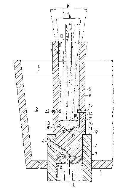
Figure 1 is a schematic sectional view of a closure
and control device at the outlet of a
; metallurgical vessel,
Figure 2 is a schematic sectional view of a further
exemplary embodiment, and - -
Figur~ 3 is a sectional view along the line III~III inFigure 2.
; Secured to the base 1 of a metallurgical vessel 2 is a
cylindrical outlet element 3 (stator). The outlet
element 3 has a lateral inlet opening 4 for the melt
situated within the vessel 2. The liquid level of the
melt is designated 5.
Mounted within the outlet element 3 is a c,losure and
control element 6 ~rotor). The lower region 7 of the
closure and control element 6 engages in the outlet
element 3. The closure and control element 6 is
provided in the lower region 7 with a flow opening 8
which may be moved into regi~try with the inlet opening
4 by rotation of the closure and control element 6
about its longitudinal axis L.

2 ~
The closure and control element 6 extends to a point
above the liquid level 5. It is provided above the
upper region 7 with an upwardly open internal space 9.
This is closed at the bottom at its floor 10. In the
exemplary embodiment the floor ~Q is situated above a
step 11 in the outer periphery of the closure and
control element 6 with which it rests on an upper edgP
12 of the outlet element 3. It is, however, also
possible to position the floor 10 lower down to below
the step 11.
Extending within the internal space 9 is a drive rod
13. Its upper, outer end (not shown) is coupled to a
drive unit-with which the drive rod 13 may be rotated
about its axis ~.
Provided at the lower, inner end of the drive rod 13
(a~ shown in Figuxe 1) is a transmission elament which
comprises a transmission block 14 and a hemispherical
member 15. The hemispherical membsr lS sits in a
concave recess 16 in the floor 10. The drive rod 13 is
so mounted by means of the hemispherical member 15 in
the closure and control element that the longitudinal
axis L of the closure and control element 6 and the
axis A of the drive rod 13 are tiltable with respect to
one another. Tolerances between the drive unit and the
position of the outlet element 3 are so compensated for
by this possibility of tilting of the drive rsd 13 with
respect to the closure and control element 6 that the
closure and control element 6 is mounted in the outlet
element 3 without restraint and may be driven.

The cross-section Q of the internal space 9 deviates
from the circular. It is, for instance, sguare,
polygonal or oval. The transmission block 14 has a
cross-seckion q which is the same as the cross-section
Q of the internal space 9. It is rotationally fixedly
connected to the drive rod 13 50 that when the drive
rod 13 is -rotated about the axis A the transmission
block 14 of the closure and control element 6 is moved
with it in a form-locking manner so that it rotates
about its longitudinal axis L. Convexity of the outer
periphery of the transmission block 14 prevents the
transmission block 14 impeding the possible tilting.
The transmission block 14 comprises a refractory
ceramic, for instance a ZrO2 or SiC ceramic. The drive
rod 13, the transmission block 14 and the hemispherical
member 15 can also constitute an integrally moulded
component of ceramic material. The latter preferably
has approximately the same coefficient of thermal
ex~ansion, particularly for the transmission block 14,
as the ceramic material of the closure and control
element 6.
The drive rod 13 with the transmission block 14 and
hemispherical member 15 withstands the high temperature
prevailing in the internal space 9 without difficulty.
It can continue to be used when the closure and control
element 6 is worn and must be replaced. Thermal
expansion of the ceramic transmission block 14 radial
to the longikudinal axis A is at most small and in any
event not larger than thermal expan5ion of the closure
and control element 6 in this region so thak there is
no danger of damage to the closure and control element

-- 6 --
6.
In the exemplary embodime~t of Figures 2 and 3 a recess
17 is formed on the floor 10 of the internal space 9.
This has a cruciform cross-sectional profile. The
recess 17 tapers conically downwardly.
. . .. .
The drive rod 13 has a cross-sectional profile which
corresponds to the cross-sectional profile o~ the
recess 17. The lower, inner end of the former eng~ges
in the rece~s 17. A rotationally fixed connection
between the drive rod 13 and the closure and control
element 6 is thus ensured. The cross-section of the
closure and control element 6- is of circular annular
shape.
The drive rod 13 comprises the described ceramic. It
can, however, also comprise a ceramic material on the
basis of Al203 or Si3N4-
Tha drive rod 13 can advantageously be produced byslurry moulding, continuous moulding or by isostatic
pressing. Not only solid profiles but also hollow
p.rof iles may be used.
Th2 drive rod 13 can also taper conically at its lower
end region. This is however not necessary. In every
case there is an empty space 18 which permits tilting
of the drive rod 13 with respect to the closure and
control element 6.

Dessin représentatif
Une figure unique qui représente un dessin illustrant l'invention.
États administratifs

2024-08-01 : Dans le cadre de la transition vers les Brevets de nouvelle génération (BNG), la base de données sur les brevets canadiens (BDBC) contient désormais un Historique d'événement plus détaillé, qui reproduit le Journal des événements de notre nouvelle solution interne.

Veuillez noter que les événements débutant par « Inactive : » se réfèrent à des événements qui ne sont plus utilisés dans notre nouvelle solution interne.

Pour une meilleure compréhension de l'état de la demande ou brevet qui figure sur cette page, la rubrique Mise en garde , et les descriptions de Brevet , Historique d'événement , Taxes périodiques et Historique des paiements devraient être consultées.

Historique d'événement

Description Date
Inactive : CIB de MCD 2006-03-11
Le délai pour l'annulation est expiré 2001-10-09
Demande non rétablie avant l'échéance 2001-10-09
Réputée abandonnée - omission de répondre à un avis sur les taxes pour le maintien en état 2000-10-10
Modification reçue - modification volontaire 1998-06-29
Lettre envoyée 1998-06-15
Inactive : Dem. traitée sur TS dès date d'ent. journal 1998-06-15
Inactive : Renseign. sur l'état - Complets dès date d'ent. journ. 1998-06-15
Exigences pour une requête d'examen - jugée conforme 1998-05-28
Toutes les exigences pour l'examen - jugée conforme 1998-05-28
Demande publiée (accessible au public) 1992-04-11

Historique d'abandonnement

Date d'abandonnement Raison Date de rétablissement
2000-10-10

Taxes périodiques

Le dernier paiement a été reçu le 1999-09-14

Avis : Si le paiement en totalité n'a pas été reçu au plus tard à la date indiquée, une taxe supplémentaire peut être imposée, soit une des taxes suivantes :

  • taxe de rétablissement ;
  • taxe pour paiement en souffrance ; ou
  • taxe additionnelle pour le renversement d'une péremption réputée.

Les taxes sur les brevets sont ajustées au 1er janvier de chaque année. Les montants ci-dessus sont les montants actuels s'ils sont reçus au plus tard le 31 décembre de l'année en cours.
Veuillez vous référer à la page web des taxes sur les brevets de l'OPIC pour voir tous les montants actuels des taxes.

Historique des taxes

Type de taxes Anniversaire Échéance Date payée
TM (demande, 6e anniv.) - générale 06 1997-10-09 1997-09-25
Requête d'examen - générale 1998-05-28
TM (demande, 7e anniv.) - générale 07 1998-10-09 1998-09-17
TM (demande, 8e anniv.) - générale 08 1999-10-11 1999-09-14
Titulaires au dossier

Les titulaires actuels et antérieures au dossier sont affichés en ordre alphabétique.

Titulaires actuels au dossier
DIDIER-WERKE AG
Titulaires antérieures au dossier
ANDREAS SCHULER
MARTIN WIESEL
RAIMUND BRUCKNER
STEVE LEE
ULLRICH HINTZEN
Les propriétaires antérieurs qui ne figurent pas dans la liste des « Propriétaires au dossier » apparaîtront dans d'autres documents au dossier.
Documents

Pour visionner les fichiers sélectionnés, entrer le code reCAPTCHA :


Pour visualiser une image, cliquer sur un lien dans la colonne description du document. Pour télécharger l'image (les images), cliquer l'une ou plusieurs cases à cocher dans la première colonne et ensuite cliquer sur le bouton "Télécharger sélection en format PDF (archive Zip)" ou le bouton "Télécharger sélection (en un fichier PDF fusionné)".

Liste des documents de brevet publiés et non publiés sur la BDBC .

Si vous avez des difficultés à accéder au contenu, veuillez communiquer avec le Centre de services à la clientèle au 1-866-997-1936, ou envoyer un courriel au Centre de service à la clientèle de l'OPIC.


Description du
Document 
Date
(aaaa-mm-jj) 
Nombre de pages   Taille de l'image (Ko) 
Revendications 1994-04-15 2 71
Abrégé 1994-04-15 1 15
Description 1994-04-15 6 206
Dessins 1994-04-15 2 79
Dessin représentatif 1999-04-20 1 41
Rappel - requête d'examen 1998-06-09 1 117
Accusé de réception de la requête d'examen 1998-06-14 1 178
Courtoisie - Lettre d'abandon (taxe de maintien en état) 2000-11-06 1 183
Taxes 1996-09-23 1 67
Taxes 1995-09-20 1 76
Taxes 1994-09-21 1 73
Taxes 1993-09-23 1 23