Note : Les descriptions sont présentées dans la langue officielle dans laquelle elles ont été soumises.
CA 02053336 2001-05-17
(a) TITLE OF THE INVENTION
PNEUMATIC TIRE
(b) TECHNICAL FIELD TO WHICH THE INVENTION RELATES
The present invention relates to a belted pneumatic tire. More particularly,
it relates
to an improvement in the belt structure , which is capable of improving tire
uniformity and
high speed durability.
(c) BACKGROUND ART
In published Japanese Utility Model Publication No. 61-15604, a belted radial
tire
having a band belt made by spirally winding cords around a breaker belt was
disclosed.
Such a band provided a tight hooping effect, and thereby a so-called "thread
lifting"
phenomenon due to the centrifugal force during high speed running can be
effectively
prevented, and durability be improved to a high level.
However, recently the requirements for tires have become very severe and are
not
satisfied by such a belt structure. In the above-mentioned belt structure, the
cords are
wound spirally such that the cords are inclined with respect to the tire
equator at a certain
angle through the whole circumferential length of the band. As a result, the
tire uniformity
is liable to be disturbed, and uneven tire deformation is caused, and
durability is lowered,
which is particularly notable during high speed running.
(d) DESCRIPTION OF THE INVENTION
It is therefore, an object of a broad aspect of the present invention to
provide a
pneumatic tire in which high speed durability is improved by improving
uniformity of belt
reinforcements .
A first broad aspect of the present invention provides a pneumatic tire
comprising a
carcass having at least one ply of cords extending between bead portions, and
a band which
is disposed radially-outside the carcass and inside a tread, the band being
made of parallel
cords wound spirally around a breaker. The band comprises two circumferential
portions
which are comprised of a parallel cord portion in which the windings of the
band cords are
laid in parallel with the tire equator, and an inclined cord portion in which
the windings of
1
CA 02053336 2001-05-17
the band cords are laid at an inclination angle of 0.3 to 5 degrees to the
tire equator. The
circumferential length of the inclined cord portion is 20 to 50 % of the whole
360 degree
circumferential length of the band.
A second broad aspect of this invention provides a pneumatic tire comprising a
carcass having at least one ply of cords extending between bead portions, and
a band which
is disposed radially-outside the carcass and inside a tread, the band being
made of parallel
cords wound spirally around a breaker. The band comprises a plurality of
circumferential
portions which are comprised of at least two parallel cord portions in which
the windings
of the band cords are laid in parallel with the tire equator and at least two
inclined cord
portions in which the windings of the band cords are laid at an inclination
angle of 0.3 to 5
degrees to the tire equator. Such inclined cord portions are disposed
substantially-
symmetrically around the tire axis. The total circumferential length of such
inclined cord
portions is not more than 25 % of the whole 360 degree circumferential length
of the band.
By a variant of these two aspects of the invention, the inclination angle is 1
to 3
degrees.
As described above, therefore, in the major circumferential portion of the
band, the
band cords are laid in parallel with the tire equator. Accordingly uniformity
of the tread
portion is improved to improve high speed durability of the tire.
(e) DESCRIPTION OF THE FIGLrRES
In the accompanying drawings,
Figure 1 is a cross sectional view of a tire according to an embodiment of an
aspect
of the present invention;
Figure 2 is a developed plan view showing the carcass and band thereof;
Figures 3 and 4 are respectively a side view and a developed partial plan view
of
another embodiment of the band;
Figure 5 is a perspective view of a ribbon of rubber used to form the band;
and
Figure 6 is a sectional view of a modified embodiment of the band.
2
CA 02053336 2001-05-17
(f) AT LEAST ONE MODE FOR CARRYING OUT THE INVENTION
In Figures 1 and 2, pneumatic tire 1 is for passenger car use and has a tread
portion
2, a pair of axially-spaced bead portions 4, and a pair of sidewall portions 3
extending
between the tread edges and the bead portions.
The tire 1 comprises a pair of bead cores 4A which are disposed one in each of
the
bead portions 4, a toroidal carcass 5 extending between the bead portions 4
and turned-up
around the bead cores 4A, and belt reinforcements 6 and 7 which are disposed
radially-
outside the carcass and inside a rubber tread.
The carcass 5 comprises at least one ply of cords extending between the bead
portions
4 and turned-up around the bead cores 4A from the axially-inside to the
outside thereof, to
form two turned-up portions and one main portion therebetween.
The carcass cords are arranged radially at 60 to 90 degrees with respect to
the
equator C of the tire to provide a radial or so-called semiradial ply
structure.
For the carcass cords, organic fibre cords, e.g., nylon, aromatic polyamide,
and the
like may be used.
The belt reinforcements in this embodiment of an aspect of this invention
includes a
breaker 6 and a band 7. The breaker 6 is disposed on the radially-outside of
the carcass
crown, and comprises radially-inner and outer plies 6A and 6B. The radially-
inner breaker
ply 6A is wider than the radially-outer breaker ply 6B. The breaker cords in
each ply are
laid at an angle of 15 to 40 degrees with respect to the tire equator C and
parallel with each
other, but crosswise to the cords in the next ply.
For the breaker cords, high elastic modulus cords, e.g., steel cords, organic
fibre
cords, e.g., aromatic polyamide fibre cords, and the like may be used.
The band 7 is the radially-outermost reinforcing cord layer, and is disposed
on the
radially-outside of the breaker 6 to extend axially across the whole width of
the breaker 6
to cover the breaker edges.
The edges F1 and F2 of the band 7 in this embodiment of an aspect of this
invention
are aligned with the breaker edges, but they can be projected therefrom.
The band 7 is made of parallel cords which are wound spirally around the
breaker 6
and continuously from one edge to the other edge thereof. The number of the
parallel cords
is preferably in the range of 6 to 20.
3
CA 02053336 2001-05-17
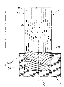
The band 7 in this embodiment of an aspect of this invention is, as shown in
Figure
2, composed of two circumferential portions, a parallel cord portion J and an
inclined cord
portion K. The parallel cord portion J is such that the windings of the band
cords are laid
parallel with the tire equator C. The inclined cord portion K is such that the
windings of
the band cords are laid at a small angle (alpha) of 0.3 to 5 degrees, more
preferably 1 to 3
degrees, with respect to the tire equator C.
The circumferential length of the inclined cord portion K is 20 to 50 % of the
whole
360 degree circumferential length. If the circumferential length of the
inclined cord portion
K is less than 20 % , the inclination angle becomes too large, and it becomes
difficult to
make such a band. If that circumferenti.al length is more than 50 % , the
parallel cord
portion J becomes too short and uniformity cannot be improved.
Figures 3 to 4 show another embodiment of the band, in which the band 7 is
composed of alternate parallel cord portions and inclined cord portions. In
this
embodiment, the band 7 is composed of alternate three parallel cord portions J
1, J2 and J3
and three inclined cord portions K1, K2 and K3.
The inclined cord portions K1, K2 and K3 have substantially same
circumferential
lengths, the total of which is not more than 25 % of the whole circumferential
length of the
band. Also the parallel cord portions J 1-J3 have substantially same
circumferential lengths.
If the total circumferential length of the inclined cord portions is more than
25 % ,
uniformity cannot be obtained, and durability is impaired.
The inclined cord portions K1, K2 and K3 (and accordingly the parallel cord
portions) are disposed symmetrically around the tire axis at substantially
regular pitch
angles (in this example every 120 degrees).
The windings of the band cords in each inclined cord portion are also laid at
a small
angle (alpha) of 0.3 to 5 degrees, more preferably 1 to 3 degrees, with
respect to the tire
equator C, and those in each parallel cord portion are parallel with the tire
equator C.
The above-mentioned bands 7 arc: formed by winding a ribbon of rubber 10 shown
in
Figure 5.
The ribbon of rubber 10 is such that the band cords 11 are embedded in coating
rubber 12 in parallel with each other along the longitudinal direction
thereof. The cross-
sectional shape of the ribbon 10 in this embodiment is a flat rectangle.
Preferably, organic
4
CA 02053336 2001-05-17
fibre cords having a heat shrinking nature, e.g., 66-nylon are used. By using
such cords,
the band cords are shrunk during vulcanization to increase the hooping force
by the band,
and the tire uniformity is improved.
In the widthwise direction of the ribbon of rubber 10, the cords 11 are laid
at
substantially regular intervals, and the number of the cords embedded is
preferably in the
range of 6 to 20 as explained above. When the cord number is less than 6, the
width W 1 of
the ribbon 10 becomes too small and the winding number or the number of
windings of the
ribbon is increased, which lowers the productivity and increases the
manufacturing cost.
When the number is more than 20, the width W 1 of the ribbon 10 becomes too
large, and
as a result the cord inclination angle in the inclined cord portion is
increased and the tire
uniformity is deteriorated.
Starting from the band edge F 1, the ribbon 10 is wound around the radially-
outside of
the breaker 6 spirally and continuously to the other band edge F2.
As shown in Figures 2 and 4, in t:he parallel cord portions J, J1, J2 and J3,
the
ribbon 10 is wound in parallel with the tire equator C, and in the inclined
cord portions K,
K1, K2 and K3, the ribbon is wound at the above mentioned small inclination
angle
(alpha) .
In the above-mentioned embodiments, the ribbon of rubber 10 is wound closely
so
that the windings are not overlapped excepting the band edge portions. In the
edge portion,
the ribbon 10 is wound along the band edge F 1, F2 at least one turn to make
the axially-
outermost winding, the whole of which is parallel with the tire equator C, and
which is
overlapped with the next winding, whereby the ends of the ribbon of rubber 10
are
prevented from being loosened, and a further reinforcement is provided at the
breaker
edges to prevent breaker edge separation failure.
Passing through the sole inclined cord portion (Figures 1-2) or all of the
inclined cord
portions (Figures 3-4), the ribbon of rubber 10 is progressed by one spiral
pitch. In other
words, in order to progress the ribbon one spiral pitch, the width of the
ribbon of rubber
(or the number of the embedded cords), the overlap width and the like are
determined
based on the above-mentioned limitations for the inclination angle and the
total
circumferential length of the inclined cord portion or portions.
5
CA 02053336 2001-05-17
If the inclination angle (alpha) is more than 5 degrees, which means that the
bent
angle of the ribbon of rubber 10 at the boundary between the parallel and
inclined cord
portions is more than 5 degrees, an undesirable stress is caused around the
boundary, and
further it becomes difficult to make such a band.
The joint of the tread rubber which is wound on the radially-outside of the
band and
the circumferential ends or joint of the breaker ply are preferably disposed
within the
parallel cord portion or portions, whereby separation failure which may be
possible during
high speed running can be avoided.
As explained above, in the two embodiments, the windings of the ribbon of
rubber 10
are not overlapped excepting the band edge portions. However, the windings can
be
overlapped all over the width as shown in Figure 6. The overlap widths L can
be constant
through all over the width, but it is also possible to vary the overlap widths
in the axial
direction such that the overlap widths increase gradually from the tread
centre towards the
tread edges, or the overlap widths in the tread shoulder regions are larger
than those in the
tread crown region. Further, it may be possible to wind the ribbon in an
opened state.
Furthermore, immediately inside the above-explained band 7, a similar band can
be
disposed so as to provide for a tire with a double-layered band structure.
As described above, in the pneumatic tires according to embodiments of aspects
of
the present invention, the spiral cord band comprises the major parallel cord
portion and
the minor inclined cord portion, whereby tire uniformity and high speed
durability are
improved.
6