Note : Les descriptions sont présentées dans la langue officielle dans laquelle elles ont été soumises.
1
OPTICAL CAF3LE
This invention relates to optical cable.
Since the commercialixation of optical cable,
various cable designs have become known. In these designs,
two relatively distinct techniques have been suggested or
used to prevent or restrict migration of moisture along
cable passageways. In one of these techniques, water
repellant materials are included in the cable structures.
These water repellant materials normally include hydro-
1o phobic greases or gels which are caused to fill cable
passageways containing the fibers. There are problems
associated with the use of greases or gels. For instance,
such materials are difficult and costly to apply into and
fill cable passageways, the filling operation necessarily
25 taking place as parts of the cable which define the passage-
ways are being farmed. In more practical terms, tubes are
made for enclosing the fibers, the tubes being extruded
around the fibers as the fibers are guided through an
extruder head together with the grease or gel which is
20 applied into the tube under pressure. Grease or gel also
makes it difficult and unpleasant to handle the fibers
during installation or repair of a cable, and at low tem-
peratures (e.g. below 0°C.) change in viscosity of the
grease or gel surrounding and contacting fibers may in-
z5 crease signal attenuation in the fibers. A further problem
is than because greases or gels may be incompatible with
economically desirable plastics which could,normally be
extruded as tubes for containing the fibers, more ex-
pensively engineered polymers may be required for the
30 tubes.
In the other technique for preventing or restrict-
ing migration of moisture along the cable passageways, it
has been suggested that the passageways should purposely
remain unobstructed and pressurized gas (i.e. air) is
35 pumped into the passageways to maintain a moisture-free
environment. Such a structure has been described in U.K.
Pateait Application 2169098A in which pressurized air is
!=
2
caused to flow along grooves formed in a central plastics
member of the cable so that the pressurized air can reach
into spaces between tubes which surround the plastics
member, each of the tubes containing optical fibers. With
such an arrangement air flow detectors would be provided to
sense a change in air flow rate, upon an escape of air
through a damaged region in the outer elements of the
cable, so as to trigger an alarm thereby signalling a need
for cable repair.
2o While this latter technique thus provides a means
for detecting cable damage, it does not provide a method
for containing or preventing worsening of the damage.
Hence, before repair can commence after the alarm signal,
water may have entered the cable and have flowed freely in
both directions~from the originally damaged region. This
flow does, of course, increase the length of damage along
the cable and necessarily increases the cost of repair
since the section of cable containing water will need to be
replaced.
The present invention seeks to provide an optical
cable which in use will lessen or avoid the above problems.
Accordingly, the present invention provides an
optical cable defining an axially extending passageway and
an optical fiber means and a water blocking means disposed
within and extending along the passageway, the water block
ing means comprising an elongate element which swells upon
contact with water to block the passageway against the flow
of water.
Any element which will provide the required water
3a blocking function will suffice. In one arrangement, the
elongate element comprises a particulate water swellable
material such as polyacrylate and an elongate carrier for
the particular material. The carrier may be of filamentary
structure, e.g. a string, or a tape which may be of open
construction (e. g. woven) So a~ to allow for flow of water
through the tape for access of the water to the water
swellable particles. Alternatively, no particulate
3
material is used and the elongate member comprises a poly-
acrylate filament or filaments spun with other filaments,
e.g. polyester, nylon or aramid filaments to form a string.
In one preferred arrangement the optical fiber
means comprises a plurality of optical fibers and a
plurality of water blocking elements extend with the fibers
along the passageway. These water blocking elements and
optical fibers may be randomly, positioned in the passage-
way. In a practical arrangement, a bundle is provided, the
2o bundle comprising a plurality of optical fibers grouped
together and a water blocking element is intermingled with
and is wrapped around the optical fibers to retain the
fibers together.
In 'the above structures according to the inven-
tion, a tube conveniently defines the passageway within it
the passageway containing the optical fiber means and the
water blocking means.
In a further practical arrangement, the cable
comprises a tube having an inner surface defining the
passageway arid the water blocking means comprises a water
swellable blacking material disposed around the inner
surface of the tube, the optical fiber means being disposed
radially inwardly of the blocking material. In this
arrangement the passageway is not completely occupied by
the optical fibers so as to provide spaces to allow for
freedom for gas flow along the passageway.
The invention also includes an elongate optical
fiber bundle comprising a plurality of optical fibers and
at least one elongate swellable water blocking element
3a which extends along the bundle.
The invention further includes a method of making
an optical cable comprising forming a tube to define a
passageway within the tube and, as the tube is being
formed, feeding an optical fiber means and at least one
elongate water swellable blocking element into the passage-
way.
Embodiments of the invention will now be
,~ w'
..~' cr
4
described, by way of example, with. reference to the
accompanying drawings, in which:-
Figure 1 is a cross-sectional view through an
optical cable according to a first embodiment and to an
enlarged scale;
Figure 2 is a cross-sectional view through part of
the cable of the first embodiment and to a larger scale
than in Figure 1;
Figure 3 is a side elevational view, to the scale
of Figure 2, of the part of the cable of the first embodi
ment;
Figure 4 is a side elevational view in cross-
section of apparatus for completing the structure shown i.n
Figure 2;
Figure 5 is a view similar to Figure 2 showing the
condition of the structure of Figure 2 after contact by
water;
Figure 6 is a view similar to Figure 3 of a modifi-
cation to the first embodiment;
2o Figure 7 to an enlarged scale, is a view similar
to Figure 1 of a second embodiment of the invention;
Figure 8 to wn enlarged scale, is a view similar
to Figure 1 of a third embodiment of the invention,~
Figure 9 is a partly diagrammatic side elevational
view of an apparatus for forming part of the cable of the
third embodiment and to a smaller scale than Figure 8;
Figure 10 is a cross-sectional view taken along
line X-x in Figure 9 and to a larger scale than Figure 9;
and
Figure 11 to an enlarged scale, is a view similar
to Figure 1 of a fourth embodiment.
In a first embodiment of the invention as shown in
Figure 1, an optical cable 10 comprises a central axially
extending tensile strength member 12 which may be formed
from any suitable material to resist undue elongate of the
cable. Such suitable material includes steel or fiberglass
strands or tensile filaments embedded in a suitable resin
s,~ :7~ rD a da ~"
f~~ ?; r, ~~, :3 e~
material. Surrounding the strength member 12 are a
plurality of elastomeric tubes 14 which substantially
contact each other around the central strength member and
extend longitudinally of the cable helically around the
5 strength member. Surrounding the tubes 14 is a corrugated
steel sheath 16 and outwardly from this is disposed a cable
jacket 18 of suitable polymeric material, e,g. a poly-
ethylene compound. Within the jacket and between the tubes
14 and around the central strength member.l2 there are
1o defined spaces 20 which are filled with a grease or gel
water blocking material provided to prevent migration of
water slang the cable. Alternatively, the water blocking
material is provided by a material which swells upon con-
tact with water so as to block the spaces between the tubes
against the flow of water. Such material may be provided
by particles of polyacrylate which are loosely inserted
into the gaps between the tubes or alternatively poly-
acrylate particles may be borne upon an elongate carrier,
or polyacrylate filaments spun along with a polyester,
2o nylon or aramid filament to form a string.. With the
alternative structure which avoids greases or gels in
contact with the tubes 14, the tubes may be formed from a
relatively inexpensive material which is not necessarily
compatible with greases or gels. Such inexpensive
materials includes compounds of polyethylene.
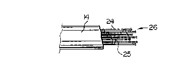
As shown by Figure 2; each of the tubes 14 defines
a passageway 22 which extends along the cable, the passage-
way containing an optical fiber means and a water blocking
means. The optical fiber means comprises a plurality of
optical fibers 24 and as shown by Figure 3, the water
blocking means comprises an elongate element 25 which
swe3:ls upon contact with water to block the passageway 22
against the flow of water. This elongate element comprises '
a filamentary structure, e.g. a string which is formed
from polyacrylate filaments together with polyester, nylon
or aramid filaments to form a string. The elongate element
25 is intermingled with the plurality of optical fibers as
.,
ro
6
shown in Figure 3 so as to hold the optical fibers in a
bundle 26. As shown, this is effected by the elongate
element 25 extending along the bundle while passing from
fiber to fiber and around each fiber in turn to hold the ,
fibers together. As described, each tube 14 has a passage-
way of a specific diameter. In the embodiment only one
elongate element 25 is provided with each bundle 26 of
optical fibers for insertion into a tube and the amount of
polyacrylate filaments in the element 25 are sufficient to
block the passageway 22 at any position at which water may
enter the passageway so as to prevent flow of water along
the passageway. Undoubtedly if the diameter of the passage-
way should be greater then two or more of the elongate
elements 25 should be included with the fibers as required.
Additional elongate elements 25 may be used intermingled
with the optical fibers as showwn by Figure 3. Further;
the bundle 26 of fibers 24 together with the elongate
elements 25 may have complete freedom for lateral movement
within the corresponding tube 14 so that the tube remains
2o essentially unblocked so as to allow for flow of air
through the tube to provide an air pressurized cable.
Alternatively the bundle of fibers 24 and the elongate
element 25 provide such a finished diameter as to substan-
tially fill the tube 14 whereby air pressurization may
become more difficult.
As part of the cable processing steps as shown by
Figure 4, a bundle 26 of the optical fibers is passed
through a core or guide tube 36 and out through an ex-
trusion orifice of an extruder head 35 while a tube 14 is
3o extruded around the group. Subsequently, the plurality of
tubes 14 containing their fibers are wrapped around the
central strength member in alternating helical fashion as
discussed above before the corrugated steel sheath 16 and
the jacket 18 is formed to complete the cable.
In use, should the cable become damaged and water
enter into any of the tubes 14, then upon contact of the
water upon the immediate swelling of the polyacrylate
results in blockage of the particular tube against the flow
of water so that the water remains in the immediate
vicinity of the damaged region of the tube. Thus, as the
extent of damage to the tube is contained then the cost of
any repair to the cable is minimized and also is
simplified. In additian, during repair the fibers 24 in
any particular tube 14 are not immediately surrounded by
grease or gel so the unpleasantness and difficulty in
handling fibers in the presence of the these twa water
blacking materials is avoided. This particular problem is
also avoided, of course, during installation of the cable.
In addition to this, all the difficulties and cost of
applying greases or gels into the passageways of a tube
during cable manufacture are also avoided while the use of
the polyacrylate water blocking material by its inclusion
into the passageways as part of an elongate element is a
particularly convenient and environmentally clean method of
ensuring that water blacking cable structures are provided.
Further to this as greases or gels are not being used in
2o the cable construction of the first embodiment, then
complex and expensively engineered polymers are not re-
quired for the tubes to make them compatible with greases
or gels. Instead, as in this present embodiment, the tubes
14 may be formed from conventional and economically
feasible extrudable polymer materials, e.g. polyethylene
compounds.
As shown in Figure 5, should there be ingress of
water into any of the tubes 14 at a damaged region, then
the water will immediately expand the polyacrylate so ws to
3o block the damaged passageway 22 to form a swelled water
blocking barrier 40 as shown in Figure 5.
The advantages in the use of the construction of
the first embodiment as discussed above all apply to the
further embodiments now to be described.
In a modification of the first embodiment as shown
by Figure 6, each of the tubes 14 is of larger diameter
such that more polyacrylate is required for blocking pur-
y4
B
poses for each unit length of tube. For this purpose in
the modification, each bundle 40 of fibers 24 includes two
or more elongate elements 25 extending longitudinally and
intermingled with the optical fibers.
In alternative modifications, not shown, the
elongate elements 25 extend along each tube 14 while not
being present in a fiber bundle.
In a second embodiment as shown in Figure 7 an
optical cable 50 comprises a central tube 52 formed from a
1o suitable polymeric material, e.g. a polyethylene compound,
the tube surrounded by a steel corrugated sheath 54 and a
polymeric jacket 56 also of suitable polymeric material,
e.g. polyethylene. Within the jacket 56 and diametrically
opposed across the axis of the cable are two tensile
strength members 58 which extend longitudinally of the
cable.
The tube 52 surrounds a passageway 60 within which
is disposed an optical fiber means and a water blocking
means for the passageway. As shown by Figure 7 the optical
fiber means and the water blacking means are constituted by
three structures each as described in the first embodiment.
i.2. comprising a bundle 26 of optical fibers 24 and at
least one elongate element 25 in the form of string. The
bundles 26 of optical fibers are inserted into the tube 52
during tube manufacture iz~ a similar manner to that
described in the first embodiment and with reference to
Figure 4.
In the event of damage occurring to the cable
sufficiently to allow for ingress of water into the passage- .
3o way 60 then contact of the water with the polyacrylate
ofthe elongate element 25 results in swelling of the poly-
acrylate to black the passageway 60 in a manner similar to
that described in the first embodiment.
In a third embodiment as shown by Figure 8, a
cable 70 has a central strength member 72 and tubes 74
surrounding the central strength member in a manner similar
to that described in the first embodiment. The difference
J , n. °,1 ~.
between this embodiment and the first embodiment is con-
cerned with the structure within passageways 86 defined
within each of the tubes 74. Instead of the passageways 86
containing bundles of fiber held together by elongate
elements 25 which are water swellable as described in the
first embodiment, in each of the tubes 74 of the third
embodiment a water blocking means is attached to the inner
surface of each tube. This water blocking means comprises
a tape 88 of open structure, possibly formed by laminated
2o paper, and the tape forms a carrier for particulate water
swellable material, i.e. polyacrylate particles, which
cover the tape. Optical fibers 90 within each of the tubes
74 thus lie radially inwardly of the tape 88: The optical
fibers 90 may be either completely free relative to one
~.5 another for lateral movement within the tube or, pre-
ferably, the optical fibers are contained in a bundle by a
helical binder (not shown) of conventional binder material
and which extends along each bundle. In any event, the.
optical fibers 90 are free to move laterally of their
2o particular passageways so that each passageway remains open
from end-to-end for the flow of air through the passageway.
In Figure 8, the tubes 74 are shown spaced apart to show
clearly the structure of each tube 74 and tape 88. In
practice, the tubes 74 contact each other.
25 During the manufacture of the cable 70, as shown
by Figure 9, a bundle 92 of optical fibers 90 is fed
through a core tube 94 which projects through an extruder
head 96 and passes slightly downstream from the extrusion
orifice 98. The water blocking means 88 is stored upon a
3o reel 100 and is fed from the reel through conventional
wrapping means 102 which farms the flat tape 88 around the
core tube 94 so as to completely enclose it with longi-
tudinally extending end regions of the tape overlapping as
shown by Figure 11. The wrapped tape 88 then proceeds
35 downstream along the core tube 94 as the bundle 92 of
optical fibers proceeds through the tube. Towards the
downstream end of the core tube 94, extrudate 104 for
forming the tube 74, contacts the tape 88 and is extruded
through the die orifice 96 so as to form a tube 74 which
become mechanically locked into the interstices of the
woven tape 88. The core tube supports the tape 88 during
extrusion so as to prevent its collapse. The finished tube
74 which now carries the wrapped tape 88 then proceeds
downstream from the extrusion orifice to cool before being
stored prior to assembly with the other elements to form
the cable 70.
In use, the cable 70 effectively provides an air
pressurizable cable. Should damage occur to the cable
sufficiently for water to enter into any of the tubes 74
then while the change in the flow of air will immediately
sound an alarm to indicate damage, the contact of water
with the particulate material on the tape 88 will immedi-
ately cause swelling of the material to block the appropri-
ate passageway 86 and restrict the flow of water to the
immediate region in which the initial damage has occurred.
Hence, upon a repair crew locating the site of the damage,
2o then an extremely short region of the cable in the immedi-
ate vicinity of the initial damage will have been flooded
by water, Accordingly, the repair process proceeds in as
simple a manner as possible while ensuring that the length
of cable which needs to be replaced is as short as
possible.
In a fourth embodiment as shown by Figure 11, an .
air pressurizable cable 120 comprises a central tube 122 of
polymeric material, e.g. polyethylene, the tube surrounded
by a polyethylene jacket 124. Within the jacket axe dis-
3o posed a plurality of longitudinally extending tensile
strength members 126.
Within the tube 122 are disposed three bundles 128
of optical fibers 130, the optical fibers being held in
position by a binder 132 extending helically around the
bundle. A water blocking means of similar structure to
that of the third embodiment is provided for the tube and
this comprises a woven or non-woven tape 134 which forms a
t~
12
carrier for a covering layer of water swellable particles
of polyacrylate. This tape 134 is bonded mechanically to
the inside of the tube during a tube extrusion process.
The assembly of the tube 122 with the tape 134 holding the
particles and the bundles 128 of optical fibers is con-
structed in a manner similar to that described in a third
embodiment and with reference to Figure 9. After manu-
facture of the tube and fiber assembly the strength members
are embedded in the jacket 124 during extrusion of the
1o jacket around the tube 122.
As may be seen from Figure 1l, the passageway
within the tube 222 is substantially open, apart from the
presence of the bundles 128, to allow for the flow of air
to provide the:pressurized cable. Should water enter the
tube 122 because of damage occurring to the jacket 124 then
a water blocking function of the particles on the tape 134
occurs similar to that described in the third embodiment.
Should the tape 124 not carry sufficient particles
fox the water blocking function; then further water swell
2o able material may be disposed radially inwardly of the tape
134. This additional water blocking material may be pro-
vided for instance by particles of polyacrylate adhering to
an elongate element in a form of one or more strings 136,
as shown in Figure 11, or by strings similar to the
elongate element 25 of the first embodiment included in the
bundles 128.