Note : Les descriptions sont présentées dans la langue officielle dans laquelle elles ont été soumises.
20~5n~7
FABRIC
BACKGROUND OF THE INVENTION
1. Field of the Invention
This invention relates to fabrics and has particular,
S but not exclusive, reference to upholstered three-
dimensional structures incorporating a first, knitted
component and a second component, which may be a woven
component.
2. Discussion of Prior Art
The manufacture of upholstered three-dimensional
structures is an extremely old technique. In one such known
structure a fabric cover is stretched over a core to produce
both an attractive and useful structure which is frequently
some form of seat.
For many years the fabric covers used in such
upholstered structures have always been of a woven nature.
More recently proposals have been made to produce
upholstered fabrics by knitting three-dimensional shapes
which can be stretched over a support to form structures
20 such as vehicle seats. An example of such a knitted
structure can be found in UK Patent Application 2,223,034A,
the contents of which are incorporated herein by way of
reference. The present invention is concerned with the
interconnection between such a knitted fabric structure and
25 a woven fabric or vinyl component, which may be required to
close off the base or back of the knitted structure to form
a closed sack. A particular example of such a structure
would be a woven seat back panel which would be sewn ~nto a
knitted main seat back structure.
2 0 ~ 7
_ -- 2
SUMMARY OF THE INVENTION
By the present invention there is provided an
upholstered three-dimensional structure including a core and
a fabric cover, the fabric cover incorporating a knitted
S component, characterised in that there is provided a woven
component sewn to the knitted component, there being
provided sewing alignment guides provided in the knitted
fabric during knitting at predetermined spaced locations
along an edge of the knitted component sewn to the woven
10 component, the woven component being provided with sewing
alignment guides in register with the alignment guides of
the knitted component.
The sewing alignment guides on the woven component may
be nicks or cut-outs in the edges of the woven fabric
15 component.
The sewing alignment guides may be additional to any
pattern evident on the visible face of the knitted
component.
The knitted sewing alignment guides may comprise lines
20 of contrasting color knitted into the knitted component.
The sewing guides may comprise lines of alternative stitch
design or may comprise lines of stitches which form a raised
portion on the surface of the fabric. The knitted sewing
alignment guides may be provided in the region of the sewing
25 area only, and are preferably not evident on the visible
face of the structure after the components have been sewn
together.
The knitted component may comprise a double jersey
structure and may be knitted from two or more colors of
30 yarn, and the sewing alignment guides may be formed by
bringing the colored yarn to the surface of the knitted
structure to form an alignment guide at predetermined
locations. The knitted component may comprise a three-
~ 3 - 20S5~67
dimensional knitted component knitted on a flat V-bed
knitting machine. The knitting machine may be under
computer control and the sewing guides may be incorporated
into the computer program to produce the alignment guides at
5 the predetermined intervals. The sewing guides may be
provided along straight edges spaced-apart at dis~tances
between 10 and 20 cm. The sewing guides may also be
provided at locations along the edge of the knitted
structure to indicate where sewing is completed and/or
10 positions where a significant change in direction of sewing
is required. The knitted structure may be knitted from
polyester yarn. The knitted structure may be the fabric
cover of a seat. The seat may be an automobile seat. The
woven structure may be a back panel or underside panel of a
15 seat back or seat base. The sewing alignment guides may be
knitted into the fabric during knitting or laid into the
fabric during knitting.
There is also provided in an upholstered three
dimensional structure including a core and a fabric cover,
20 the fabric cover incorporating two knitted component~ sewn
together along respective edges thereof, the improvement
which comprises the provision of sewing alignment guides
knitted into one at least of the knitted fabric components
at predetermined spaced locations along that edge of the
25 knitted component to be sewn to the other component. The
present invention further provides knitting in alignment
guides to both of the knitted components to be sewn
together. The sewing alignment guides may comprise lines in
the fabric or may comprise nicks formed in the fabric or
30 both lines and nicks.
The present invention yet further provides a method of
manufacturing a three-dimensional structure from at least
two fabric components, at least one of the fabric components
being a knitted component, which includes the steps of:
35 knitting the knitted component and incorporating sewing
alignment guides in the knitted component during the
2 ~ 7
-- 4
knitting step, the sewing alignment guides being additional
to any pattern evident on the visible face of the knitted
component; providing a second component being a woven
component or another knitted component, the second component
5 having alignment guides provided in or on the second
component; aligning the alignment guides on the first
knitted component with respective alignment guides on the
second component, and sewing the two components together.
BRIEF DESCRIPTION OF THE DRAWINGS
By way of example embodiments of the present invention
will now be described with reference to the accompanying
drawings, of which:-
Figure 1 is a perspective view of a seat in accordance
with the invention,
Figure 2 is a view of Figure 1 along the line of arrow
II,
Figure 3 is a perspective view of a prior art fabric
structure and a woven structure superimposed one on the
other prior to sewing,
Figure 4 is a perspective view of the two fabric
structures of Figure 3 after sewing,
Figure 5 is a perspective view of two structures in
accordance with the present invention with a portion of
Figure 5 enlarged,
Figures 6(1) to 6(9) are stitch diagrams of nine
courses of stitches,
Figure 7 is a schematic diagram of a knitted-in notch,
and
20~fi~
-- 5
Figures 8(1) to 8(8) are stitch diagrams of eight
courses of stitches.
DESCRIPTION OF PREFERRED EMBODIMENTS
Referring to Figure 1, this shows a seat indicated
5 generally by 1 suitable for use in a car or other form of
vehicle. The seat incorporates a squab 2 and a back 3.
Essentially the seat squab comprises a cover 4 stretched
over a core 5. Typically the core would comprise a foam bun
of some suitable upholstery foam reinforced with a metal
10 reinforcing structure. The core 5 is shown behind the
broken away line 6 of the cover 4. Typically the base of
the squab 2 would incorporate tubular loops by me~ns of
which the fabric 4 can be stretched tightly over the bun of
the base 5. A typical example of a base is shown in Figure
15 2 of British Patent Specification 2,223,034A referred to
above.
The seat back 3 comprises a knitted face component 7
shown clearly in Figure 1. Sewn to the back of the seat
back 3 is a woven panel 8 shown in Figure 2. The woven
20 panel 8 is sewn to the knitted fabric face panel 7 along the
line 9. As shown in Figure 2 the line 9 extends completely
around the woven panel 8; in some cases, however, the base
of the panel 8 i.e. the portion 10 of line 9, would not be
sewn to the knitted fabric member 7.
Woven fabrics tend to be less extensible than k~itted
fabrics and unless a great deal of care is adopted ln sewing
the structures of a knitted and woven fabric together, the
results can be as illustrated in Figure 4. In Figure 3
there is shown a woven fabric panel 11 superimposed on a
30 knitted fabric panel 12, prior to sewing the two components
together on a conventional sewing machine. In a
conventional sewing machine, the foot of the machine holds
the two fabrics together whilst a serrated advancing
mechanism operating beneath the fabric 12 advances the
2Q~5~fi7
- 6 - O
fabrics under the needle. The advancing mechanism tends to
stretch the fabrics and simply sewing together a knitted and
woven component produces the results shown in Figure 4. The
line of sewing 13 is shown clearly in Figure 4 and it can be
5 seen that the upper panel 11 of woven material has stretched
to a smaller extent than the lower panel 12 of knitted
material.
When sewing together conventional woven structures for
products such as automobile seats it is known to incorporate
10 registration marks along the edges of the components to be
sewn so that the machinist can keep the edges in proper
registration and if material has to be gathered to produce
the desired cosmetic effect, the machinist can do this while
keeping the registration marks visible. Typically
15 registration marks are provided by producing nicks in the
fabric edge or producing cut-out V-shapes. It will be
clear, therefore, that the registration marks have to be
produced either as a separate operation in the manufacture
of the sewn structure or the cutting pattern has to
20 incorporate the registration mark cutting knives.
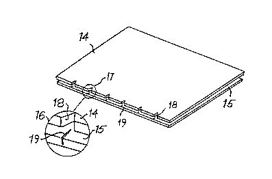
Figure 5 shows a woven panel 14 prior to sewing onto a
knitted panel 15 wherein the knitted panel 15 incorporates
the sewing alignment guides of the present invention. The
sewing alignment guides are shown more clearly in the
25 enlarged portion in circle 16 which is an enlargement of the
circle 17 of Figure 5. The woven panel 14 incorporates
notches 18 in a conventional manner. However, the knitted
panel 15 has knitted into it sewing guides 19 during the
manufacture of the knitted panel 15.
Typically the knitted panel 15 would be a double jersey
knitted panel knitted on a flat V-bed machine. The knitted
panel would incorporate one or two rows of stitches of a
contrasting color knitted in to give each alignment guide
lg. Because the design of the knitted panels 15 can now be
35 carried out on a computer, it is possible to produce perfect
20~67
-- 7
registration of the sewing guides 19 onto the knitted
component 15 without the need for any separate step in
producing the sewing guides. There are, therefore,
significant advances in accuracy and significant advantages
5 in manufacturing time by incorporating the knitted-in sewing
guide in accordance with the present invention.
The knitting-in of the guides can be carried out by
conventional techniques. The knitting techniques useful to
the invention will be found in the following works of
10 reference.
"Rnitting" by H Wignell, Published by Pitman Publishing
1971 Edition, London
"An Introduction to Weft Rnitting" by J A
Smirfitt,Published by Merrow Technical
Library, Watford, England, 1975
"Advanced Rnitting Principles" Edited by C Reichman,
Published by National Rnitted Outerwear
Association, New York, New York, 1964
"Fully Fashioned Garment Manufacture" by R W
Mills,Published by Cassell, London, 1965
"Rnitting Technology" by D J Spencer, Published by
Pergamon Press, London, 1983.
The knitting may be carried out on a flat bed machine
such as:-
a Stoll CMS Selectanit machine, for details see
Rnitting International, May 1990, pages 26-
28, or
a Steiger Electra 120FF machine, for details see
Rnitting International, April 1990, page 96,
20~067
-- 8
or
a Shima Seiki SES machine, for details see Rnitting
International, September 1989, page 60.
The details of how alignment guides may be knitted-in
5 can be seen clearly in the stitch diagrams shown in Figures
6(1) to 6(9) and in Figure 7.
The nine diagrams shown in Figure 6 comprise nine
courses used to knit-in a V notch which would look similar
to the notch cut into the woven fabric and illustrated at 18
10 in Figure 5.
Figures 6(1) to 6(4) represent a four course repeat of
a plain faced bird's-eye backed structure. Figure 6(5)
represents the releasing or pressing off of the four sets of
loops held on the left-hand selvedge needles which produce
15 the V notch. Figures 6(6) to 6(9) represent a further four
course repeat which is identical to that of the c~urses
shown in Figure 6(1) to Figure 6(4) so that in total there
is produced a structure in which there is a V notch on the
edge of the fabric.
In Figure 6(1) the first course shows all of the
needles in a lower bed 20 being knitted on by the traverse
of a conventional yarn carrier whilst every alternate needle
in an upper bed 21 is knitted on. For convenience, the
needles in the upper bed are labelled a, b, a, b etc. It
25 can be seen that in Figure 6(1) only the needles a on the
upper bed 21 are knitted on in the first course, and the
needles b are not knitted on. In the second course, only
the needles b are knitted on in the upper bed 21 and none of
the needles in the lower bed 20 are knitted on at all. In
30 the third course, all the needles in the lower bed 20 are
again knitted on whereas in the upper bed 21 only the
needles labelled b are knitted on.
2Q550~
g
In the fourth course, no needles in the lower bed 20
are knitted on whereas in the upper bed only the a needles
are knitted on.
The four course repeat for the plain faced bird's-eye
5 back structure may be used as many times as is required. To
form the notch 18, the stitches on the left-handl four
needles are pressed off during the next traverse of the yarn
carrier as is shown by the four pairs of x in the stitch
diagram of Figure 6(5), the needles for the remaining
10 stitches are not raised and are not knitted on during that
traverse of the yarn carrier. The next four courses
illustrated in stitch diagrams 6(6), 6(7), 6(8) and 6(9) are
identical to the respective courses illustrated in Figures
6(1) to 6(4). This total sequence then gives an edge with
15 a notch similar to the notched edge of the sheet 14 of
Figure 5. The stitches in the knitted fabric are shown
schematically in Figure 7, where it can be seen that a notch
22 is formed between stitches in a course 23 and stitches in
a course 24. Stretching the fabric shown in Figure 7 will
20 tend to widen the notch 22.
To knit-in a colored line on the reverse side only of
a knitted fabric, the knitting can be carried out in
accordance with the stitch diagrams illustrated in Figures
8(1) to 8(8). In Figures 8(1) to 8(4) there is represented
25 a plain faced bird's-eye backed structure produced with two
colors of yarn, a lighter yarn 27 shown with a solid line
and a darker yarn 28 shown with a dashed line. In the
center of each Figure, between oblique lines 25 and 26, the
birds-eye backing sequence is replaced by a concentration of
30 loops of a single color as can be seen in Figures 8(2) and
8(4) where the yarn 28 being knitted on needles of an upper
bed 30 is a different color to the yarn 27 knitted on the
needles of the upper bed 30 and on needles of a lower bed 29
as shown in Figures 8(1) and 8(3).
In Figure 8(1), which shows the first course in a
20~67
- 10 -
sequence, the yarn 27 is knitted on all of the needles in
the lower bed 29, but only on the alternate needles labelled
a in the upper bed 30, and then only outside the region
defined between the oblique lines 25 and 26. Within the
5 region defined between the lines 25,26, the yarn 29 is not
knitted on the needles of the upper bed 30. In the next
course, shown in Figure 8(2), the darker yarn 28 is k~itted
only on the upper bed. Outside the region defined between
the oblique lines 25 and 26 knitting is effected only on the
10 alternate needles 6. Within the said region the yarn 28 is
knitted on all of the needles in the upper bed 30.
In the next course, shown in Figure 8(3) the lighter
yarn 27 is again knitted on all of the needles in the lower
bed 29, but on only the alternate needles b in the upper bed
15 30 that lie outside the region between the oblique lines
25,26. In the fourth course of the sequence shown in Figure
8(4) the darker yarn 28 is knitted on only the needles in
the upper bed 30, and then only on the needles labelled a
outside the region between the oblique lines 25,26. Within
20 the said region 25,26 the yarn 28 is knitted on all the
needles of the upper bed.
This knitting sequence is followed by a conventional
bird's-eye backed knitting sequence repeated every four
courses and shown in Figures 8(5) to 8(8). The structure is
25 knitted with two yarns 31,32, which can be the same color or
different colors. The yarn 32 can, if required, be the same
color as yarn 28, and the yarn 31 can, if required, be the
same color as yarn 27. It will be seen that the stitch
structure shown in Figures 8(5) to 8(8) is the same as the
30 bird's-eye backed structure shown in Figures 6(1) to 6(4).
Thus, by using a different colored yarn in the center
of the knitting sequence illustrated in Figures 8(1) to
8(4), there is produced on the reverse of the fabric a mark
which corresponds to line 19 illustrated in Figure 5 on
35 sheet 15.
205S~6~
- 11 -
As is mentioned above, typically the knitted panel
would be a double jersey structure and would typically be a
polyester double jersey structure knitted from two colors of
5 yarn with the less dominant on the back of the fabric being
brought through onto the face to produce the knitted line
19. Alternatively thlcker yarns may be knitted-in to
produce the line 19 or a separate color may be knitted-in or
the stitches may be altered in such a way as to produce a
10 visual mark 19.
If two knitted components are to be joined together
there is a further advantage in knitting-in the registration
points so that, for example, knitted V-shapes can be
incorporated into the panel 14 and the edges can be knitted
15 with the registration points already in position. It will
be understood that the sewing alignment guides on the
knitted component 15 although shown as a line could, in
fact, be a knitted V. Furthermore, it will be appreciated
that either registration marks - such as dashed lines along
20 the edge could be knitted-in if required. It will also be
appreciated that the sewing alignment guides may be laid
into the fabric during knitting rather than knitted in. A
thread is laid in when it is incorporated into the knitted
structure without being formed into interengaging loops by
25 the needles of the knitting machine.
The sewing alignment guides are preferably only
provided where required i.e. in those regions where
components are to be sewn, are provided only on the parts of
the fabric not visible when the structure is in use, and are
30 additional to any pattern provided on the fabric for
aesthetic reasons. The visible face of the fabric is that
side of the fabric seen by the viewer when the structure is
in use e.g. the outside of the seat.