Note : Les descriptions sont présentées dans la langue officielle dans laquelle elles ont été soumises.
- 205S213
FIELD OF THE lN Vhr. llON
This invention relates to a process for separating
oil as bitumen from oil sands and, more particularly,
relates to a process for beneficiating bituminous froths by
removal of water and solids.
BACRGROUND OF THE INVEN~ION
The commercial extraction of oil as bitumen from oil
sands involves the use of the "hot water" process in which
mined oil sands typically are introduced into a rotating
drum and slurried with steam and hot water at approximately
80C. The drum discharge, freed from rocks and clay lumps
by screening, is further diluted with hot water to about 50%
solids and a temperature of about 70 to 75C, and pumped
into a process vessel for the initial separation of bitumen
from the oil sand slurry and recovery of bitumen as a
primary froth product. The slurry discharged from the
bottom of this vessel, and the middlings from an
intermediate zone, are either further processed separately
or combined and then processed by air flotation to recover
additional bitumen from these streams. The flotation of
bitumen in one or more vessels is termed a secondary
recovery process. A sand-water slurry discharged from the
bottom of these vessels becomes tailings and is discarded.
In secondary recovery processes, air is introduced
into the slurry and the subsequent flotation of the bitumen
yields a lower grade froth which contains higher contents of
water and solids than obtained from the initial, or primary
separation. The secondary froths are then combined into a
20~213
settling vessel or "cleaner" where some of the excess water
and solids are removed. Secondary froth is combined with
primary froth to become the overall bituminous froth
product. The cleaner bottoms slurry is returned to the
flotation circuit.
The term "solids" used herein refers to inorganic
solids such as fine quartz sand and silt and clay minerals.
In the commercial processes, bituminous froths
produced in the secondary recovery circuit contain
significant amounts of residual water and solids, e.g. 60 to
80% water and 5 to 10% solids. At the process temperature,
solids and water partially separate from the bitumen
resulting in a secondary bituminous froth containing
approximately 30-35% bitumen, 50-55% water and 10-20%
solids. This froth is combined with the primary froth which
contains approximately 65% bitumen, 25% water and 10%
solids. Combining the secondary froth stream with the
primary stream results in the overall bituminous froth
product.
In subsequent treatment of this froth, water and
solids are further removed by dilution of the froth with a
diluent solvent such as naphtha. This diluted bitumen is
treated by centrifugation in the commercial process to
remove water and solids. A reduction in the water and
solids content of the froth would result in higher
capacities in the centrifugation process and reduction in
the hydrocarbon losses to the slurry.
205~213
Canadian Patent No. 857,306 issued on December 1,
1970 to Dobson discloses the treatment of middlings by
flotation to produce an aerated scavenger froth which is
passed to a settling zone for separation of mineral matter
from the froth. The separation occurs at the ambient
temperature of the froth, normally 70-75C.
U.S. Patent 3,338,814 issued on August 29, 1967 to
Given et al. describes a process whereby froths produced by
hot water extraction of bitumen are dehydrated by heating to
temperatures from 225 to 550F (preferably 350 to 450F).
The dehydrated bitumen, containing 5% to 25~ solids is then
subjected to cycloning or filtration to remove solids. In a
variation to the basic process, a light hydrocarbon can be
added to the dry bitumen to improve the filtration step.
The hydrocarbon can be recovered by distillation and
recycled. This is essentially a two-stage process that
requires a considerable amount of energy in order to obtain
a satisfactory degree of water and solids removal.
U.S. Patent No. 3,901,791 issued on August 25, 1975
to Baillie discloses a method for upgrading bituminous froth
by diluting the froth with a hydrocarbon diluent boiling in
the range of 350 to 750F, heating the diluted froth to a
temperature in the range of 300-1000F and settling the
froth in an autoclave at a pressure in the range of 0 to
1000 psig, diluting settled tailings with the diluent and
centrifuging the diluted tailings to provide a centrifugal
froth.
20~S213
U.S. Patent No. 4,035,282 issued on July 12, 1977 to
Stuckberry et al. discloses a process for recovery of
bitumen from a bituminous froth in which the froth is
diluted with a hydrocarbon solvent and subjected to a two-
stage centrifugation for removal of water and minerals.
Solvent is added before each stage of centrifugation.
U.S. Patent No. 4,648,964 issued on March 10, 1987 to
Leto et al. discloses a process for separating the
hydrocarbon fraction from a tar sands froth in which the
froth is pressurized to about 1000 psig and heated to about
300C to enhance gravity separation, and the constituents
separated at a reduced pressure.
U.S. Patent No. 4,859,317 issued on August 22, 1989
to Shelfantook et al. proposes three stages of inclined
plate settlers to remove water and solids from bitumen
froths. This process is carried out at approximately 80C
using naphtha as diluent in a 1:1 volume ratio based on the
oil content in the froth.
Canadian Patent 915,608 issued on November 28, 1972
to Clark et al. describes a process for removing water from
a bituminous froth by imparting shearing energy to thereby
coalesce water from at least 25 pounds of water per 100
pounds of bitumen to less than about 15 pounds of water per
100 pounds of bitumen. The process was carried out at
temperatures between about 35 to 49C.
The processes disclosed in the foregoing patents are
complex and necessitate the use of expensive solvents or
require high temperatures and/or pressures in an effort to
2055213
beneficiate the bitumen froth.
It is the principal object of the present invention
to provide a simple process and an apparatus for reducing
water and inorganic solids from bituminous froths without
the use of solvents.
Commercial extraction processes use water heated to a
nominal temperature of about 70 to 75C. Recent
development work is aimed at reducing this processing
temperature as low as 10C to achieve energy savings and
reductions in processing costs. However, reductions in
processing temperature have the undesirable consequence of
increasing the solids content in the froth products, thereby
placing more emphasis on the development of froth cleaning
processes to improve froth quality. In addition, froths
produced at these low temperatures are extremely viscous and
difficult to process.
It is another object of the present invention to
provide a process and an apparatus to enable the production
of high grade froth products from lower temperature oil
sands extraction processes.
SUMMARY OF THE lNv~llON
In its broad aspect, the present invention relates to
a process for improving the quality of froth derived from
the extraction of bitumen from oil sands in which effective
separation of water and solids is achieved by heating lower
quality froth products to a temperature in the range of 80
to 100C. The heated froth is fed into a gravity settling
vessel at a level below a bitumen-water interface between a
205S213
froth layer floating on a quiescent body of water whereby
water and solids contained in the froth separate from the
froth stream, and the oil rises to accumulate in a bitumen-
enriched overflow stream. The solids fall by gravity to the
bottom of the gravity settling vessel.
The apparatus of the invention for the removal of
solids from a bituminous froth comprises, in combination, a
vessel having a perimeter wall and a cone bottom for
receiving a bituminous froth containing bitumen, solids and
water whereby the bituminous froth forms a froth layer
floating on a quiescent body of water defining a bitumen-
water interface, means for discharging bituminous froth as
an overflow and water containing solids as an underflow from
the vessel, an injector manifold suspended horizontally
within the vessel and below the bitumen-water interface,
said injector manifold having a plurality of equispaced,
inwardly facing openings formed therein for the inward
discharge of bituminous froth into the body of water, and
conduit means in communication with the injector manifold
for feeding bituminous froth to the injector manifold.
The vessel preferably has a cylindrical perimeter
wall and said injector manifold preferably is a ring
manifold suspended horizontally within the vessel concentric
with the vessel wall. The injector ring manifold may have a
plurality of equispaced , inwardly and outwardly facing
openings formed therein for the radially inward and outward
discharge of bituminous froth into the body of water. A
level probe preferably is mounted in the vessel in
2055213
electrical communication with the means for discharging the
water containing solids as an underflow for detecting the
level of the bitumen-water interface whereby the level of
the bitumen-water interface can be controlled by controlling
the rate of discharge of the underflow.
BRIEF DESCRIPTION OF THE DRAWINGS
Figure 1 is a schematic flow sheet of an embodiment
of the process of the invention;
Figure 2 is a perspective view of an embodiment of an
apparatus of the present invention;
Figure 3 is a side view of the apparatus shown in
Figure 2;
Figure 4 is a plan view of said apparatus of the
invention;
Figure 5 is a graph showing bitumen separation in
heated froth;
Figure 6 is a graph showing efficiency of water
removal; and
Figure 7 is a graph showing efficiency of solids
removal.
DESCRIPTION OF 'ln~ ~K~KK~U EMBODIMENT
With reference to the schematic flowsheet of Figure
1, primary froth from primary vessel gravity separator 10
normally containing 10 to 20% by volume air are partly
deaerated in tower 12 having a structured packing 14, well
known in the art. Froth flowing into the top of the tower
12 is distributed as falling droplets throughout the tower
by the grid packing. Steam is introduced from below the
20~5213
grid near the bottom of the tower at 16 resulting in heating
and deaerating of the descending froth droplets. The inlet
froth temperature can range from less than 10C to about
70C. The froth temperature at the deaerator outlet can
range from 60 to 85C depending on the flow rates of froth
and steam to the deaerator, the preferred temperature being
from 65 to 75C.
The heated froth is then pumped by pump 18 through a
heat exchanger 20 to further increase the temperature to
the range of 85 to 100C, preferably about 90C.
It will be understood that although cold froth can be
heated from the process temperature to approximately 90C in
a single stage by either direct steam contact in the
deaerator 12 or by indirect heating with a heat exchanger
20, these two methods individually do not appear optimum for
a large scale commercial operation. Heating of froth by
direct steam contact is inefficient when the final froth
temperature rises above 80C. Heat exchangers are difficult
to operate with cold froths which have extremely high
viscosities in the temperature range of 0 to 50C.
The middlings 28 from primary vessel gravity
separator 10 are passed to flotation cell 38 for air
flotation of bitumen and depression of solids. The float
product 40 is passed to deaerating tower 32 and settled
solids discharged as tailings. The tailings 26 from
primary vessel 10 are passed to secondary vessel gravity
separator 24 which is in series therewith, the settled
solids discharged as tailings and the middlings 25 passed
2055213
back to flotation cell 38 in which air flotation produces
float product 40. This is combined with float product 30
from vessel 24 and heated by steam in tower 32 to a
temperature in the range of 60 to 85C for deaeration. The
deaerated froth is pumped by pump 42 through heat exchanger
44 and heated to about 90C before introduction into gravity
separation vessel 46, to be described, for cleaning of
solids and water from the froth. The concentrated froth
overflow 48 passes to pump box 50 and is pumped to froth
tank 22 where it is combined with hot froth from heat
exchanger 20 and the froth product 54 pumped to a froth
treatment. Settled solids can be flushed with water 23 and
solids and water discharged as tailings 25.
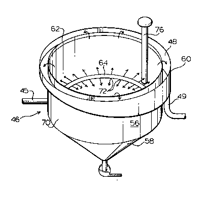
With reference now to Figures 2-4, separation vessel
46 comprises cylindrical wall 56 with cone bottom 58.
Peripheral trough 60 surrounding rim 62 is adapted to
receive froth overflow 48 for discharge through conduit 49
to pump box 50 and to a froth storage tank.
Injector ring conduit 64 in communication with feed
pipe 45 from heat exchanger 44 is suspended horizontally
within vessel 46 concentric with wall 56 below bitumen froth
layer 66 preferably to between 2 and about 12 inches from
interface 68 defined between froth layer 66 and quiescent
body of water 70.
Injector ring conduit 64 has a plurality of
equispaced, inwardly and outwardly facing openings 72, 73
formed therein for the radially inward and outward discharge
of heated froth from heat exchanger 44 into quiescent body
2055213
of water 70. The level of interface 68 is monitored by a
level probe 76 which controls the speed of variable speed
discharge pump 78 to maintain the interface at the desired
level.
The bitumen phase in the stream of incoming
bituminous froth heated to about 90C and introduced into
body of water 70 rises to the interface 68 and coalesces
with froth layer 66.
A significant portion of the water and solids
introduced with the froth remains in the body of water for
effective removal from the froth. Additional drainage of
water and solids from the bitumen phase further enhances the
quality of the bituminous froth.
It has also been found that the addition of water to
the suction 82 of pump 42 (Figure 1) to dilute and mix the
froth prior to discharge into vessel 46, such as by mixing
froth in centrifugal pump 42 followed by heating in heat
exchanger 44 prior to discharge of the froth into the
quiescent body of water in vessel 46 by injector ring 64,
surprisingly results in enhanced removal of water and
separation of solids from the froth. One purpose of the
mixing referred to above, with or without the addition of
water, is therefore to promote coalescence of small droplets
of water into larger water particles which settle faster:
effective mixing prior to settling is designed to achieve
this.
Although the description has proceeded with reference
to a cylindrical vessel with a ring manifold, it will be
2055~13
12
understood that the shape of vessel and manifold is not
critical and the vessel configuration can, for example, be
rectangular, such as a square, with a compatible manifold
shape.
The process of the invention will now be described
with reference to the following non-limitative examples.
Bituminous froth was supplied to direct and indirect
steam heaters by an experimental extraction pilot plant of
the type shown in Figure 1 operating at a feed temperature
between 45 and 60C. The heated froth was passed into a
cleaning vessel 46 for reduction of solids and water content
in the froth. The direct heater was a tower 32 containing a
structured packing 14 and indirect heating was provided by a
heat exchanger 44. Either of the pilot plant heaters 32 or
44 was capable of heating froth to 90C and the
effectiveness of each type of heater could be tested
separately. Examples of hydrocarbon separation tests for
each of the heating methods are given by the following
examples.
EXAMPLE 1
Bituminous froth at an initial temperature of 70C
was heated to about 91C by direct steam contact in
deaerator 32 and then passed directly to a separation vessel
46. Separation results are shown in Table 1.
205~213
13
TABLE 1
Rate Temp. % % % %Bitumen
(kq/hr) (C) Bitumen Water Solids Distribution
Separator
Feed 583.2 91 32.4 51.516.2 100.0
Separator
Overflow 340.5 91 54.2 38.19.5 94.5
Separator
Underflow 242.7 91 4.4 70.225.5 5.5
EXAMPLE 2
Bituminous froth at an intial temperature of 48C
was heated to about 88C by indirect steam heating in heat
exchanger 44 and then passed directly to a separation
vessel 46. Separation results are shown in Table 2.
TABLE 2
Rate Temp. % % % % Bitumen
(kq/hr) (C) Bitumen Water Solids Distribution
Separator
Feed 442.7 88 35.8 53.211.0 100
Separator
Overflow 245.4 88 58.5 30.211.3 90.6
Separator
Underflow 197.3 88 7.7 81.810.5 9.4
Substantial improvements in bituminous froth quality
were obtained independent of the type of heating used.
Figure 5 illustrates the performance of the process
of the invention for froths heated to 90C and containing
bitumen in amounts of 10% to 60% by weight of froth in the
feed to the froth cleaner 46. A surprising upgrade of
bitumen from as low as 10% by weight to the range of 40% to
60% by weight, with an average bitumen content of about 50%
2055213
by weight, was obtained.
A comparison of Figures 6 and 7 indicates that the
efficiency of water and solids removal from the heated froth
was dependent on the water content of the froth; i.e. the
lower the bitumen content and hence the greater the water
content, the greater was the removal of water and solids.
No significant improvement of bitumen content was obtained
in froths exce~;ng 60~ by weight bitumen.
It will be understood, of course, that modifications
can be made in the embodiment of the invention illustrated
and described herein without departing from the scope and
purview of the invention as defined by the appended claims.