Note : Les descriptions sont présentées dans la langue officielle dans laquelle elles ont été soumises.
20~36:~
TURKEY NEST TIMER
BACKGROUND OF THE INVENTION
The present invention relates to a nest
assembly for encouraging egg production by domestic fowl
and, more particularly, to a nest assembly that provides
an improved nest basin with indicators and a timer to
determine the duration a hen remains on the nest.
Domestic egg production farms, such as turkey
farms, provide large banks of individual nesting
assemblies in which a hen can lay an egg. After the hen
has entered the nest and has laid the egg, the hen may
tend to remain sitting on the egg and become what is
commonly referred to as "broody". A broody hen will
want to remain on the nest to hatch eggs and will no
longer produce eggs.
In order to delay hens from becoming broody,
an operator can remove the hens from the nesting
assemblies if they remain too long. Some attempts have
been made to provide ejectors for the hen to eject the
hen from the nest after a time period, but these are
generally unsatisfactory. Proper flock management
requires that the operator know the status of each
nesting assembly in order to keep the nests available
for hens that are laying eggs. Specifically, the
operator must know when a hen is present on a particular
nesting assembly and, more importantly, the amount of
time the hen has remained on that nesting assembly.
Given the large number of nesting assemblies used on the
farms and the large number of hens in most flocks, it is
impossible to manage by periodic visual checking of the
nests.
There is a need for an improved nesting
assembly, which indicates entry and presence of a hen
205~361
and which indicates when the hen remains on the nesting
assembly more than a set time. Such nesting assembly
should provide the desired features without discouraging
hens from entering the nesting assembly or complicating
the task of gathering eggs.
SUMMARY OF THE INVENTION
The present invention relates to a nesting
assembly, which provides an indication of hen occupancy
time to indicate hens which should be removed from a
nest and for encouraging domestic fowl egg production.
The nesting assembly comprises a support member, and a
support plate mounted to the support member. The
support plate has an upper surface with a depression
formed thereon to serve as a nesting basin. The nesting
basin is oval in shape with inwardly inclined basin side
walls.
The nesting basin further includes an inclined
lower basin wall, which slopes rearwardly to an egg
discharge aperture located in a portion of the basin
side wall. A conveyor or trough is provided beneath the
aperture to receive and transport eggs exiting the nests
to an egg collection location.
A weight sensor is mounted to the nesting
assembly that detects presence of the hen from the
weight of the hen. In one preferred embodiment, the
sensor is a switch that mounts below the lower basin and
surface. The sensor provides a signal representative of
lower basin wall downward deflection from the weight of
a hen. In an alternative embodiment, the deflection
sensor comprises a pressure sensitive switch mat
positioned on the lower basin surface. The mat is
formed from upper and lower conductive plates with a
compressible insulating material interposed between the
20~3~
conductive plates. The insulating material includes
apertures which align with conductive dimples formed on
one of the conductive plates. Presence of the hen is
detected when the weight of the hen causes the upper
conductive plate to deflect and compress the interposed
insulating material allowing the dimples to project
through the aperture in the insulating material and
engage the lower conductive plate and make electrical
contact. With electrical leads attached to both the
upper and lower plates and current supplied from a
suitable power supply, the mat functions as a switch.
In either embodiment, the sensor is coupled to
an input of an indicating circuit. The indicating
circuit comprises a visual indicator and a timer that
are both initiated by the sensor used when there is
sufficient hen weight. The timer has an adjustable
preselected time duration and a "time elapsed" output
coupled to a second indicator. The timer output
controls the second indicator if the sensor does not
provide indication that the hen has vacated the nesting
assembly (a return to no-load condition) before the
preselected time duration has expired. The construction
disclosed provides a nest that can be used in existing
nest assemblies so retrofit is not a problem. Flock
management is enhanced because the production of hens is
easily monitored and hens which want to brood and hatch
eggs (that is, become "broody") can be identified and
culled.
BRIEF DESCRIPTION OF THE DRAWINGS
Figure 1 is a top plan view of a nesting
assembly constructed in accordance with the invention;
Figure 2 is a sectional view of the nesting
assembly of Figure 1 taken along line 2-2 of Figure 1;
20~53~1
Figure 3 is a combined block and schematic
diagram of a timing circuit of the present invention;
Figure 4 is a sectional view of a nesting
assembly with a pressure sensitive mat;
5Figure 5 is an exploded perspective view of
the pressure sensitive mat of Figure 4; and
Figure 6 is a sectional view of the pressure
sensitive mat taken along line 6-6 of Figure 5.
DETAILED DESCRIPTION OF THE PREFERRED EMBODIMENTS
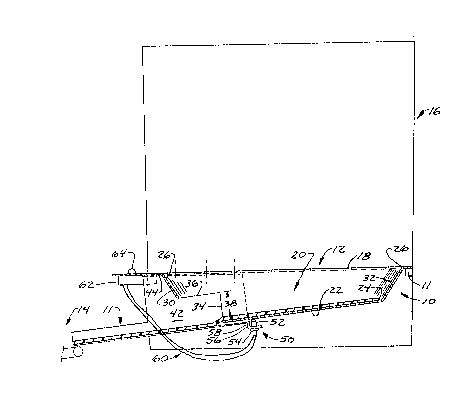
10In Figures 1 and 2, a nesting assembly 10 of
the present invention is shown. Generally, nesting
assembly 10 comprises a hen support plate 12 where a hen
desiring to lay an egg is supported, and a chute or
trough 11 that directs the egg from the nesting assembly
10 to an egg collection conveyor 14. As shown in Figure
2, nesting assembly 10 is mounted to a support member 11
generally in a horizontal plane either in the open, or
- more commonly, within a nesting enclosure 16. When
mounted in nesting enclosure 16, nesting assembly 10
provides a nest bottom. One side wall of a conventional
nesting enclosure 16 is shown. Any desired or standard
nesting enclosure can be used.
The hen support plate 12 has an upper edge
surface 18 surrounding a nesting basin 20, which is an
oval depression located substantially in the center of
hen support plate 12. Nesting basin 20 has a natural
nest shape for the hen that desires to lay an egg.
Nesting basin 20 includes a generally flat
inclined lower basin wall 22 that slopes rearwardly.
Lower basin wall 22 is centered generally on hen support
plate 12. As shown in Figure 2, a nesting basin 20 has
a generally conical or tapered side wall 28 formed
between a lower basin surface edge 24 and an upper
2~5~3~
basin surface edge 26, so the side wall 28 inclines
inwardly toward the lower basin wall 22. Furthermore,
since inner lower basin wall 22 slopes downwardly and
rearwardly, portions of basin side wall 28 forming a
rear basin wall portion 30 have an overall depth from
upper surface 18 to lower basin wall 22 that is greater
than those portions of basin side wall 28 forming a
front basin wall portion 32.
An aperture 34 is located in basin rear wall
portion 30. Aperture 34 is fairly large and allows eggs
deposited in nesting basin 20 to travel under
gravitational force to trough 11. An upper aperture
edge 36 is formed on basin rear wall portion 30 at a
height 38 from lower basin wall 22 to allow egg passage
to trough 11. A removable mat 25 is provided to cover
lower basin surface 22 and trough 11 to prevent the egg
from breaking.
Trough 11 comprises a trough plate 40 and
trough side panels 42. Trough 11 is positioned under
hen support plate 12 such that aperture 34 overlies
trough plate 40. Trough 11 is either separately
supported in this position or as shown in the preferred
embodiment is mounted to a lower surface 44 of support
plate 12 with mounting tabs 46 formed on upper edges 48
of trough side panels 42. The lower basin wall 22 is
somewhat flexible and resilient, so when a hen sits on
the nest the lower basin wall 22 deflects downwardly,
and when the hen leaves, the wall 22 returns to an
initial position.
To detect presence of a nesting hen on nesting
assembly 10, a deflection sensor 50 is used. In one
embodiment shown in Figure 2, sensor 50 comprises an
electrical switch 52 that is mounted to switch bracket
20~3~
54. Switch bracket 54 is secured to a mounting tab 56
formed on a front edge 58 of trough 11 below the lower
surface of lower wall 22. The switch 52 is mounted to
a member which provides a reference position for
detecting bottom wall 22. Hen presence is detected when
the weight of the hen causes lower basin wall 22 to
deflect downwardly and engage sensor 50. Switch 52 is
electrically connected with wire leads 60 to an
indicating unit 62 that has indicating lamps 64 and 66
mounted thereon.
In an alternative embodiment shown in Figure
4, sensor 50 comprises a pressure sensitive mat 90 that
lies on top of lower basin wall 22. Mat 90, as shown
in detail in Figures 5 and 6, comprises a non-conductive
resilient and compressible sheet 92 interposed between
- two conductive plates 94 and 96. As shown in Figure 5,
sheet 92 has a plurality of through holes 98.
Individual holes 98 align with corresponding conductive
dimples 100 formed on conductive plate 94. The dimples
extend partially through aligning one of the holes 98.
In this embodiment, mat 90 detects hen presence when the
weight of the hen causes smooth plate 96 to deflect
downwardly and compress sheet 92. With sheet 92
compressed, the ends of conductive dimples 100 control
plate 96 to form in effect the closing of an electrical
switch represented by switch 52. Mat 90 is electrically
connected to indicating unit 62 with leads 60A which are
connected to the plates 94 and 96. The electrical
connection formed by the ends of dimples 100 and plate
96 is opened when the hen vacates the nesting assembly
and sheet 92 returns to an uncompressed state. Plates
94 and 96 can be formed from any conductive material
such as 24 gauge galvanized metal with dimples 100
-` 20$5361
formed as depressions thereon. Sheet 92 can be formed
from any suitable compressible material such as a soft
resilient foamed plastic with non-conductive or
insulating properties. The mat 90 may be enclosed
within a sealed plastic envelope 108 to protect the
components from getting dirty.
An indicating circuit 68 for indicating unit
62 is shown in Figure 3, and includes a power supply 72
supplying a positive voltage level to supply line 74 and
a reference voltage level to supply line 76. Supply
lines 74 and 76 provide power for a timer 70. Timer 70
has an adjustable preselected time delay which is
initiated when an initiating voltage is provided to an
input line 78 by closing the electrical connection of
sensor 50. Indicator lamp 64 and a biasing resistor 80
are connected in parallel between supply line 74 and
input line 78. Sensor 50 is connected with leads 60
between input line 78 and supply line 76. The indicator
lamp 64 also is powered (lit) when the electrical
connection of sensor 50 is closed.
An output voltage from lines 74 and 76 is
provided by timer 70 on an output line 82 after the
elapsed time period. Indicator lamp 66 connected
between output line 82 and supply line 76 is lit when
the time period of timer 70 elapses.
Indicating circuit 68 indicates initial
presence of the hen on nesting assembly 10 and also
indicates if such presence exceeds a predetermined
duration of time. Initially, with no hen present on the
nesting assembly, the electrical connection of sensor 50
is open. With the connection open, indicator lamps 64
and 66 are off and timer 70 is not running.
~ 20~3~ ~
As stated earlier, when a hen is present on
nesting assembly 10, the weight of the hen causes the
electrical connection of sensor 50 to close, so
indicator lamp 64 is turned on and timer 70 is
initiated. Indicator lamp 64 remains on and timer 70
will run to the end of its preselected period if the hen
remains on the nesting assembly to keep sensor 50
closed. If the hen vacates the nesting assembly before
the preselected time duration of timer 70 has expired,
sensor 50 returns to its open state, indicator lamp 64
turns off and timer 70 will reset in a conventional,
known manner. However, if the hen remains on the
- nesting assembly for a duration longer than the
preselected time duration set on timer 70, output line
82 then is connected to line 74 by an internal timer
switch to turn on indicator lamp 66. Indicator lamp 66
signifies to the operator that the hen currently present
on the corresponding nesting assembly has been there too
long for normal egg laying and should be removed.
Removal of the hen, whether forcibly or voluntarily,
again restores indicatinq circuit 68 to its initial
state with indicator lamps 64 and 66 off and timer 70
reset. As shown in Figure 3, an optional test switch 88
may be provided to verify that indicator lamp 66 is
functioning properly.
In summary, the present invention provides an
improved nesting assembly that encourages domestic fowl
egg production. Whether supported in the open or
installed as a nesting bottom in a new or existing
nesting enclosure, the nesting assembly provides vital
nest status information. Intrusive indicators such as
buzzers could be incorporated to provide this status
information. However, the present invention preferably
20~3~ ~
includes an adjustable timer coupled to non-intrusive
indicator lamps. In the preferred embodiment, these
indicator lamps are color coded so that the operator can
quickly ascertain the present status of each nesting
assembly without fear of disrupting the hen currently on
the nesting assembly or discouraging other hens from
entering a vacant nesting assembly. A green light is
used to indicate hen occupancy and a red light used to
indicate excessive time of occupancy.
Although the present invention has been
described with reference to preferred embodiments,
workers skilled in the art will recognize that changes
may be made in form and detail without departing from
the spirit and scope of the invention.