Sélection de la langue

Search

Sommaire du brevet 2057209 

Énoncé de désistement de responsabilité concernant l'information provenant de tiers

Une partie des informations de ce site Web a été fournie par des sources externes. Le gouvernement du Canada n'assume aucune responsabilité concernant la précision, l'actualité ou la fiabilité des informations fournies par les sources externes. Les utilisateurs qui désirent employer cette information devraient consulter directement la source des informations. Le contenu fourni par les sources externes n'est pas assujetti aux exigences sur les langues officielles, la protection des renseignements personnels et l'accessibilité.

Disponibilité de l'Abrégé et des Revendications

L'apparition de différences dans le texte et l'image des Revendications et de l'Abrégé dépend du moment auquel le document est publié. Les textes des Revendications et de l'Abrégé sont affichés :

  • lorsque la demande peut être examinée par le public;
  • lorsque le brevet est émis (délivrance).
(12) Demande de brevet: (11) CA 2057209
(54) Titre français: IMPRIMANTE A JET D'ENCRE POUR MACHINES A AFFRANCHIR
(54) Titre anglais: LIQUID-JET PRINTER FOR FRANKING AND VALUE-STAMPING MACHINES
Statut: Réputée abandonnée et au-delà du délai pour le rétablissement - en attente de la réponse à l’avis de communication rejetée
Données bibliographiques
(51) Classification internationale des brevets (CIB):
  • B41J 02/145 (2006.01)
  • B41J 02/15 (2006.01)
  • B41J 25/308 (2006.01)
(72) Inventeurs :
  • DIETRICH, KLAUS (Allemagne)
  • GUNTHER, STEPHAN (Allemagne)
  • KNOTH, NORBERT (Allemagne)
  • MIEHE, FRIEDRICH-VIKTOR (Allemagne)
  • THIEL, WOLFGANG (Allemagne)
(73) Titulaires :
  • FRANCOTYP-POSTALIA G.M.B.H.
(71) Demandeurs :
  • FRANCOTYP-POSTALIA G.M.B.H. (Allemagne)
(74) Agent: SMART & BIGGAR LP
(74) Co-agent:
(45) Délivré:
(22) Date de dépôt: 1991-12-06
(41) Mise à la disponibilité du public: 1992-06-09
Licence disponible: S.O.
Cédé au domaine public: S.O.
(25) Langue des documents déposés: Anglais

Traité de coopération en matière de brevets (PCT): Non

(30) Données de priorité de la demande:
Numéro de la demande Pays / territoire Date
P 40 39 742.4 (Allemagne) 1990-12-08

Abrégés

Abrégé anglais


27260-1
ABSTRACT
For a liquid-jet printer for franking and value-stamping
machines that generates script and graphic characters and symbols
on a receiving surface, it is proposed that the nozzles be
arranged concavely above the receiving surface. This is done so
that the fictive focal point of the liquid jets be beneath the
receiving surface. A distance-measuring system serves to
compensate for the different thicknesses of the receiving surface
by lowering and raising the print head.

Revendications

Note : Les revendications sont présentées dans la langue officielle dans laquelle elles ont été soumises.


- 6 -
27260-18
THE EMBODIMENTS OF THE INVENTION IN WHICH AN EXCLUSIVE
PROPERTY OR PRIVILEGE IS CLAIMED ARE DEFINED AS FOLLOWS:
1. A liquid-jet printer for franking and value-stamping
machines that generates script and graphic characters and
symbols on a receiving surface by ejecting droplets from nozzles,
these nozzles and the associated control means being held in a
guide plate of a print head, and arranged at an angle to the
direction of movement of the receiving surface, characterized by
a concave arrangement of the nozzles in the print head relative
to the receiving surface, the liquid jets from the individual
nozzles intersecting at a fictive focal point beneath the
receiving surface, a distance measuring system that is associated
with the print head measuring the distance between the nozzles
and the receiving surface and serving to compensate for different
distances.
2. A liquid-jet printer as defined in claim 1, character-
ized by a concave formation of the guide plate.
3. A liquid-jet printer as defined in claim 1, character-
ized by a concave arrangement of the nozzles in a guide plate
that is configured so as to be plan parallel.
4. A liquid-jet printer as defined in claim 1, character-
ized in that the distance sensor is integrated into the guide
plate of the print head.
5. A liquid-jet printer as defined in claim 1 and claim 4,
characterized in that the distance measuring system uses
reflection of an optical or acoustic signal to measure the

- 7 -
27260-18
distance.
6. A liquid-jet printer as defined in claim 5, character-
ized in that a laser beam is used as an optical signal.
7. A liquid-jet printer as defined in claim 1, claim 4
and claim 5, characterized in that optico-electronic means are
used to detect the optical signal.
8. A liquid-jet printer as defined in claim 1, claim 4
and claim 5, characterized in that a monolithic integrated CCD
line sensor is used as an opto-electronic detector.
9. A liquid jet printer as defined in claim 1, claim 4
and claim 5, characterized in that the distance measuring system
uses an ultrasound depth finder system.

Description

Note : Les descriptions sont présentées dans la langue officielle dans laquelle elles ont été soumises.

21~72~
2726Q-18
The present invention relates to a liquid-jet printer
for franking and value-stamping machines that generates script
and graphic characters and symbols on a receiving surface by
ejecting droplets from nozzles, these nozzles and the associated
control means being held in a guide plate of a print head, and
arranged at an angle to the direction of movement of the receiv-
ing surface.
It is known that spray nozzles used in printers can be
installed in a fixed print head in such a way that these are
either parallel to each other or such that their longitudinal
axes intersect at a point in the print plane (DE-30 04 530 Al).
In order to achieve a close nozzle raster pattern,
other ink mosaic printers have the nozzles installed with their
tips close together. When this is done, the number of nozzles,
combined with a plurality of ink reservoirs, permits variegated
colouring of the print image (DE-34 20 921 Al).
In li~uid-jet printers of this kind, precise adjustment
of the print heads is essential in order to ensure a pri.nt image
that is always faultless. In addition, it is necessary to use a
receiving surface that is guided and of a standard thickness so
that there is always an e~ual distance between the receiving
surface and the print head or the outlet orifices of the spray
nozzles, respectively.
When such printers are used in franking machines, one
encounters the problem that the receiving surfaces are of
different thicknesses, and thus the distance between the print
nozzles and the receiving surface has to be determined anew on

- 2 - 2~
27260-18
each occasion and the necessary adaptations made.
It is an object of the present invention to create a
liquid-jet printer that always ensures the same distance, even
in the case of receiving surfaces that are of different
thicknesses, and that ensures a differentiated, close print
raster by the arrangement of the nozzles within the print head.
There~or~ the present invention seeks to provide a
liquid-jet printer for franking and value-stamping machines that
generates script and graphic characters and symbols on a
receiving surface by ejecting droplets from nozzles, these
nozzles and the associated control means being held in a guide
plate of a print head, and arranged at an angle to the direction
of movement of the receiving surface, characterized by a concave
arrangement of the nozzles in the print head relative to the
receiving surface, the liquid jets from the individual nozzles
lntersecting at a fictive focal point beneath the receiving
surface, a distance measurlng system that is associated with the
print head measuring the distance between the nozzles and the
receiving surface and serving to compensate for different
distances.
The sub-claims describe additional, advantageous
measures according to the present invention.
The advantage of arranging the nozzles on a concave
curve relative to and with a fictive focal point of the liquid-
jets beneath the receiving surface is seen in enhanced resolution
of the print image as it corresponds to the interval between the
nozzles in the print head.
-

-~ 3 2~7~
27260-18
The present invention will be described in greater
detail below on the basis of the drawings appended hereto. These
drawings show the following:
Figure 1: The construction, in principle, of a print
head;
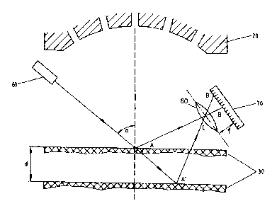
Figure 2: A schematic diagram showing the distance-
measuring system.
In these drawings, identical parts bear the same refer-
ence numbers.
The nozzles 10 are held in the guide plate 20. In the
example shown in figure 1, the guide plate 20 is configured so
as to be concave. Instead of a guide plate of concave shape,
this can also be planar. In this case, the outlet openings of
the nozzles 10 are arranged concavely relative to the receiving
surface 30. The nozzles 10 are so orientated in their position
relative to the receiving surface 30 that the fictive focal
point 50 of all the liquid-jets 40 lies~below the receiving
surface 30. The printing width is determined by the interval
between the edge jets 41, ~2 at the level of the receiving
surface 30. Because of the position of the fictive focal point
50 beneath the receiving surface 30, high resolution of the
character is achieved despite the relativel~ wide interval
between nozzles 10 that are adjacent to each other.;
Be~ause the liquid jet printer is used for fran~ing
and value-stamping machines, special measures are needed to
ensure a consistent print image on various receiving surfaces
30, for such receiving surfaces 30 can be of different
thicknesses. As an example, letters can be of different
: '

~7~
-- 4 --
27260-18
thicknesses as a result of the number of pages that they contain
and/or because of the thickness of the paper used for the
envelopes. Pre-printed cheques that pass through value imprinting
machines can be of paper of different thicknesses. A consistent
print image cannot be achieved with a fi~ed arrangement of the
print head and the surface for the receiving surface, relative
to each other.
For this reason, the printer system according to the
present invention has an associated distance measuring system 60,
70. This distance measuring system 60, 70 incorporates an
associated control system that ensures a uniform distance
between the guide plate 20 and the receiving surface 30 by
raising or lowering either the print head or the base for the
receiving surface.
In order to determine the distance, a process that
permits a high level of resolution in the range of tenths of a
millimeter is needed. The distance measuring system 60, 70 is
arranged within the print head and is preferably integrated into
the guide plate 20. Distance sensors that operate on the echo-
sounding principle, as well as those that are based onreflection of optical signals can be used as measuring processes.
A preferred embodiment is described in greater detail
below. A laser 60, e.g., a CO2 laser, which is directed onto the
receiving surface 30 at an acute angle, generates a focussed
laser beam that strikes the surface of the receiving surface 30
at angle a and generates a patch of light A. Some of the
scattered laser beam passes along the line AL. An image B of the
: ':
; .

~ 12~
27260-18
light patch A is formed within the plane of focus oE the imaging
lens (L)80, which is of focal length f. If the scattering
surface of the receiving surface 30 is displaced vertically,
for example by a thinner envelope, this will generate the point
of impact A' and the image point B'. The distance BB' in the
focal plane of the imaging lens 80 is a measurement for the
vertical displacement d of the surface of the receiving surface
30:
f*d
: BB' = ----------------
(AL - f) cos (~)
A system of several opto-electronic detectors is
arranged in the focal plane of the imaging lens 80 in order to
record the distance BB'. Monolithic integrated CCD (charge
coupled device) line sensors can be:used advantageously for
this purpose.
.
, . ., " . . .

Dessin représentatif
Une figure unique qui représente un dessin illustrant l'invention.
États administratifs

2024-08-01 : Dans le cadre de la transition vers les Brevets de nouvelle génération (BNG), la base de données sur les brevets canadiens (BDBC) contient désormais un Historique d'événement plus détaillé, qui reproduit le Journal des événements de notre nouvelle solution interne.

Veuillez noter que les événements débutant par « Inactive : » se réfèrent à des événements qui ne sont plus utilisés dans notre nouvelle solution interne.

Pour une meilleure compréhension de l'état de la demande ou brevet qui figure sur cette page, la rubrique Mise en garde , et les descriptions de Brevet , Historique d'événement , Taxes périodiques et Historique des paiements devraient être consultées.

Historique d'événement

Description Date
Inactive : CIB de MCD 2006-03-11
Le délai pour l'annulation est expiré 1994-06-06
Demande non rétablie avant l'échéance 1994-06-06
Réputée abandonnée - omission de répondre à un avis sur les taxes pour le maintien en état 1993-12-06
Inactive : Demande ad hoc documentée 1993-12-06
Demande publiée (accessible au public) 1992-06-09

Historique d'abandonnement

Date d'abandonnement Raison Date de rétablissement
1993-12-06
Titulaires au dossier

Les titulaires actuels et antérieures au dossier sont affichés en ordre alphabétique.

Titulaires actuels au dossier
FRANCOTYP-POSTALIA G.M.B.H.
Titulaires antérieures au dossier
FRIEDRICH-VIKTOR MIEHE
KLAUS DIETRICH
NORBERT KNOTH
STEPHAN GUNTHER
WOLFGANG THIEL
Les propriétaires antérieurs qui ne figurent pas dans la liste des « Propriétaires au dossier » apparaîtront dans d'autres documents au dossier.
Documents

Pour visionner les fichiers sélectionnés, entrer le code reCAPTCHA :


Pour visualiser une image, cliquer sur un lien dans la colonne description du document. Pour télécharger l'image (les images), cliquer l'une ou plusieurs cases à cocher dans la première colonne et ensuite cliquer sur le bouton "Télécharger sélection en format PDF (archive Zip)" ou le bouton "Télécharger sélection (en un fichier PDF fusionné)".

Liste des documents de brevet publiés et non publiés sur la BDBC .

Si vous avez des difficultés à accéder au contenu, veuillez communiquer avec le Centre de services à la clientèle au 1-866-997-1936, ou envoyer un courriel au Centre de service à la clientèle de l'OPIC.


Description du
Document 
Date
(aaaa-mm-jj) 
Nombre de pages   Taille de l'image (Ko) 
Dessins 1992-06-08 1 25
Abrégé 1992-06-08 1 24
Revendications 1992-06-08 2 56
Description 1992-06-08 5 175
Dessin représentatif 1999-04-22 1 11