Note : Les descriptions sont présentées dans la langue officielle dans laquelle elles ont été soumises.
20~7233
.4_C~FFE ~1~1;HI~lE ~r ~CME~TX~15E
~CK~ OUND ~ h,~ I l`lY~L~
The invention rela~es t~ ~ ~offee machin~ f~r
~mes~ic use.
The pri~r art 6~mb;-ace~ vari~us ~yp~ f offe~
~5 mach~e ~r ~xl;:lu~ive~ly d~ne~ic u~e: ~ho ma~hine~
- ~omprise a ba~ n w~ich a~ ~er~ica~l t~wer d~fining
a re~e~rvoir-sealed ~oiler s~t)ly st~nd~. ~hi~
'ce~wer i~3 e~uipped~ us~a~ feribrly~ wlth
resi~;tance~ connectable wi~h ~ ~r~e Of electric
lV c:urrent wi~h thQ aim of he~tim3 ~he water pr~3s~F~t
in ~he re~ vo ir .
. ' , '
C)n it~ upper ~nd the t~wer i5 cornec:t~d ~ ~y mea~s
of m~h~nic~l uni~n ~ r e:~ample screw~ t~
~ ~5 hor~i~ontal pr~jec'cing prolunç~ation~ .whi~h ~
-~ ~ d6~finei ~y ~ le~ n~ cond~t ~ rli1;Q ~he
re~ rv~ir with ~n ~utl~ mou~h ~ vleusly widar
:: th~n thc~ ~ndui~ ~ ~r~-anged at ~h~la 1'r6~6~ ~nd o~ ~h~
pr~lur~atiun ~and inferi~rly equipped w~h a
2C~ pas~a~ f~lter 3t~bly and ~oaxially fi~sed on the
~ .
~; ' .
,
2~7233
~utlet mGuth itself ~ thi~; out}~t m~uth i~
equipp~d, below an~ late?r~lly t~ th~ filt~rl with
a ~ayGnQ~ 30i~'c c:ouple! (with ~ s~mi-arc
c~n1:ormation~ aim~d at p~sitioning ~nd stably
0~ bl~ck}n~a, af~er rt31a~ive r~tati~ he c~1'fe~
p~wd~r c~ntainer ~acirl~l the said c~tl~t mcuth and
equipp~d with the ~sual ou~t n~zzle~ o1' ~h~
dr i nk .
~; ' ' .
t ~h~ level ~f 'Gh~ 4u~1e~ m~th~ for reasc"~ Gf
u~er saf~Y1;y~ ian ~n-~f~ valYa is ~nvisia~ 1ror l;ho
s~i~ corldui~, which v~lve~ i~s man~l~lly c:~3mmandod by
~ ~ .
means ~ a 1 e~er or but ~n a~ran~e~ ~n th~ upper
par~ he ~LUt ~ mouth .
lS
Coffee machine~; madl3 in ~hi~ way have 11CjWeVel~
som~ drawback~ o1t a mqtchan~ 41 " saal iny and 1~a~e~y
nat~r~: the~ pro~ecting~ unic~n of ~he horizonti~l
prolung~tion wl~h the t~wer: h~s shvwn i~elr to
; have, ~v-r ~ perio~i ~f titne an~ se" a certain
eruc~ural weaknc~s (e~p4ci~11y with r6~gard ~o ~h~
echanical uni~n ~IystQ~ " in ~h~t th~ c:on~inu~l
~ ~ .
a~tachln~-dutach~n~ u~ bh~a. co1'1''e~e cQnl;ain~r ln ~h~
D- tl,et mo~uth prc~v~ a l~eninçl ~ ur ~v~n ~a
: 25 br~4kinu~ o~ ~ ~he conn~qctic~n bet~2n eho
;;
;
20~7233
pr~lung~ti~n and the tower: thls o~ e~ the
,~onstrust~rs of su~h machin~ mak~ the c~nduit
in metallic material in er~r ~o ~ry to ~chi~v~ a
r~as~nable dur~t~n ln term~ ~f time , thu~
OSincre~çln~ pr~ducti~n ~ts.
The ~akne~ noted ~ove is.als~ present in th~
~n-off ~lve ~f the ~am~ con~u~t, which valve can
~ive ri~e ~o dQfe~ts'~u~ ~ it~ cvnnecti~n with
h~ ~cbivation d~vic~ ~rr~n~e~ int~rnally S~ th~
~` outlet ~o~th and ~hu~ c~n ~en~rate unwanted escap~
~f hot w~t~ or ~t~m al~o ~t the mom~nt of
~; detachment ~f ~h~ c~ffe~ ~ontainQr; furth~rmore~
there i~ the ~onstant dan~-r, i~h0r~nt ~n the
lSm4n~l ~CtiV~tiQn 5y5t~1n 0~ the ~alve~ ~n that the
ser mi~aht f~ryet : to çloc;~ the . val~ b~ore
d-tachin~ th~ cof~--e contain~r . Thu~ th ,e abov---
describ-~ sy1~teo do~Y: not ~nstitut~ a t~i~roughiy
de1'ect-~re~ ~fety 3~lutior~ ov6~r a ~-~sonabl~
80~~ ~p~rio~ o1' u~
~Y o~;th~. INVENTION
m 171' the pr~ent inve~n~ i~n i~ th~r-~r~ to
minat- th~ abov~-d~scribed ~rawback~ by
Sprovi~ing a :d~mestic c~ff~e m~h~n~ which i9
';
.
.
-:
.
.` ' ' ` ,
:
. . ~ . '
20~7233
s~oli~5 c~mp~ct, pra~ical in ite c:orstitu~nt
,c~ar ts ~ and funct ion~1 ly saf~ .
The inve~rtion" a~3 ch~racteris3Q~ the ~laim~
05 which~foll~w~ ~t~ains the~ abc-ve-describ~d ~ y
providing a c~ 2e-machin~ equlppQd with a
prej~?ctlns;~ s~le~n~ent compri~inç;l an ~utl6~t n~ou'6h ant~
~i~al~d sa~et~ means~ haviny ~ l;hr~ugh-chamber f~r
wa~er i whlch pr~ectin~3 eleme~nt i5 r~tat~bl~
iC c~nn~c~e~ with anarm ~n~ pp~r~ed by ~ bracketi
: ~ . the pr~ tLnç~ el~ ~nt i5 s;lidably rotatable on
it~ own v~rtical axis with re~pect ~v a~ c~ns~ui~
ter ~;he attachn~nt with ~bseq~n'G retation c~f 4
ntai ner ~ i n an ex 'creln~ p~s i t i~n corr~pon~i ing to
i5 th~ op~n p~ition of th~ wa~r pas~y~ ~ frem a
t~wer to ~n ~tlet mvu~h ~nd vic~-versa; st~ppinU
eans ~re~ envisa~l-d Qn th~ proi~ct~ng el~m~nt and
on the brack~t, which ~oppine~ me~ns a~:S on the
sa~d pro~ecting el~ment in ~ h ~ way as ~t~bly to
20~ d~fin~ ~ehe :~ two ~xtr~me open and c:los~?d p~tium~
o~ th~ ~:~ndui ~ .
;~ IEF I~E!3CRIP,TIQN ~f ~;he~ nt~WTNG8
h~ ~dvan~ and ~ chara~::t~ris,ti~s ~ h~
5 ~ lnYent lon wl I l b~t~ter ~ ge fr~m the ~tai le~d
.
,' ~ '
. . . .
;:
~ . ., , ., - , ,. ~ . .
: ~ ' ' . ' . . - - - , . . ~ ..
', , '. .
20~7233
~st:rIpt~n which follows~ made with reforeru::e to
th~ ~cc~mp~nying drawings, illu~s~ratin~ an
emb~dim~nl; which i~ purls.ly in ~h~ ~orm ~f ~ non-
limi~in61 eK~mpl~ in which:
05 - Figurq~ 1 ~hows a lateral vi~?wJ with ~i~me p~r~s
rem~ved in or~r ~tter to ~vide~n~:e others~ of ~he
cv~fe~ machine 4bi~:t ~ the pr~3~nt invention;
- FiQ~re ;~ shows~ in ~ v~w ~rom ab~vel the cvffee
m~c:hin~ 3ure 1 ~l th s~me p~r~ moved be1;~r
1~ t~ ~vi~en e c~ther~;
- Figur~ 3 sh~ws, in sid~--vi~w ~nd with s~sme p~r-~s
removed in ~rder better to evidenc~ hth~rs, a
' c~nstr~iv~ v~ric~nt ~f one part ~f th~ coffee
: m~chirle ~f fi~r~2 1;
lS - FigLlre!s :~a and 3t~ ~3h~w,, bo~h in side view wi~h
s~mQ par1;s r6~m~ve~i be~er to ~vi~nc~ R~hers, a
p~rticular ~f fi5~ur~ two ~fferent ~p-rative
po~;i t ions; - ~
~ ~ .
- Fig~r~ 4 shows" in gi~e view anr~ with ~OA~e part~
removed ~l3tter t~ evid~?nce ~h~rs~ an~h~r
c~nstru~iv~r v~iant ~f a part ~f th~!a cof~
m~chint~ o~ ul-o 1
Fi~lre !5 sh~w~, in sl~e vi6~w and w~th s~me p~rt~
rem~ved ln ordur t)~ r to ~vidRnce others
,
~S furth~r v~rlant t)f a part ~he cot~ee maet-i~e o~
: , .
.. ,
. .
. - ~ - .
20~7233
b
f i gu1 e L i
- Figur~s ~ and ~a show5 in side Yiew ar~d with
sDme p rts rem~ved in ~jrder b~at~r t~ eYid~n~e
o thers~ and in ~ ViQW fr~m ~b~ve, ~nGther v~r~ant
~5 ~f ~ part c!f the ~of~ee ma::hine ~f ~igure 1;
- Figur~s 7 ~nd ~3 show, ~oth i~ ,ngitudinal ..
s~tion~ ~ secDnd~ry conduit ~f th~ Ff~ea
mach}n~ e4~1ipped wi~h clbsing m~ns f~ he said
con~ui ~ .
~ESI~ I PT ~ ON t~ he E~i`E ;F~ E~ ~E~
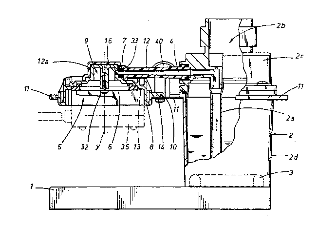
With re~ererle~ t~ bhe dr~wi~s~ th~ c~ff~ machinet
comprise~i ~ base 1 s~ ~upport ~f a ~ert~c~al tow~r
Z, which tc~er 2 i~ arranye~ on one sld~ of th~
said . base 1, ~n~ which t~w~r 2 ~fines a scale!d
ntainer-boi1er for w~t~r (~ ur~ . Th~
ts~er ~ hao a ~e~ledly cl~able inlot op-ning 2b
: a~el is ec~ peJ with h~?at~ng me~n~ 3 ~C:ting ~n
the sdid tc~wer a i, such ~ way as ~ permit of
~` 2C~ incr4asi~g the t~mpora~ur~a RF th~e w~t~r ~p to ~t~
vaper~ing ~as c~n t~ n in fi~res 1 ancl Z
~he~3e n~ns3 are eo~6t'3 l;ut~tl by an ~ctri~: iao
~`; re5~sta~nc~ arran~ed around t~ bc~t~c~m ~ th6~ t~w~r
and conneGltab1~ to a n~rmal el~tr~c Itall
switch'~ .
~ ' .
''
.: .
. ' ' :
20~7233
The t~wer ~ in ~hH ill~lstrated. case has two
di~t~nct ~emi-part~ lndica~d by ~ and 2d ~o~
which th~ ~emi-part Zc d~fin~s th~ Upp~r par-t~ ~nd
~aid tower 2 i~ ~onn~c~d horj.xon~ally by m~ns
05 an arm l~ e~uipped with a t~ndui~ ~ to ~ cir~uiar
wat~r outle~ m~uth 5, ~rran~ed ~cin~ ~nd direc~.y
above the ~ther ~ide ~f the ~e i~ which mo~th 5
is eq~ipp~d with a ~ilter 6 ~r ~h~ p~ss~e o~ the
wa~er, whish fil~r ~ i5 fi~ c~ax~ally on ~he
~ai~ olltlQt ~Uth ~l in the fl~r~s a seeo~dary
l~teral sDnduit 40 i~ ~lsc illustr~te~1 usablR f~r
the vap~ris~ w~er~ ~ c~f~ee-p~wder c~nbainer 35
~llu~rated sshem~tica~ly by a discon~inuo~s line
~ in ~ re l~ equipped with a relative handle ~n~
- lS er~gati~n sp~ut~ ic con~ e to th~ sai~ ou~le~
m~uth 5~ by meanc of a b~y~net i~int c~pl~ ~4 in
r~t~ion ~bout ~ v~rti~l axi~ Y parallel t~ th~
to~er ~
ZO ~. The ~onduit 4 is equipp~d with saf~ty and se~ ig
mea~s 7 astin~ ~n the said con~ and aim~
permittin~ of openir~ ~nd r~s~ectivQly ~ inu ~he`
~: pressuri6ed wat~r p~ e ~r~m the t~w~r ~ W~i~h
tew~r 2 i5 ob~iou~ly internally ~qu~pped with ~
water aepiratin~ col?d~it 2~ coa~ial k~ the
. :
~ .
:~'
,
B 20~7233
C~ 4 ~rlec ~ he o~tle~
msu~ S.
-rhe t~w~r ~ ~n~ ;ages a cir~ ar prc~3f~cting
bS elem~ 87 ~cmprisin~ l:;he o~lYt mo~h 5 arlcl the
saf~?ty m~ns ~ ? and h2~s ~ ~chr~ugh-chamb~r ~ ~o,r
the w~t~r WhiC:h chamber 5~ i~ r-ct~ ? ~n ~tg ~wn
V'rti~ 'i5 Y with r~spect t~ th~ Dnduit
be~w!en two ~?xbr~m~ posjiti~r-~i corre~3p~n~1~r-9 ~v ~h~?
1~ ~p~3n p~si ~ f~r t:hA w~ter p~aye from th~ t~w~?r
i~ tc th~ o~ltl~t mGL~h 5 ~ h~ ~1V~Yd posi~ion
~r th~ p~;sag~? ~f th~ w~t~?r ~rom th~ ~w~r Z ~o
kh~ C?Ut~l~t mo~lth ~; this i~ ~;utJseslu~n~ bo the
a-tta~chm~nt wl~h subsec)ut3nb rot~ti~n ~ the
lS c:c?n~e~iner 35 anc~ vi ~ a-v~rs~ lt~r~ pre!c.i~t~ly~ ~h~
pr~? j~cting ~l~me~n~ 8 is ~iupp~r~ed by ~ hr~cl;e?~ 11
~ni~d with ~h~ ~ower Z ~ f~ul~ anrl 2); th~
sa~ ~;~ack~t 1 i is In ~c~ la~ sà~ bvdy -
pl~ in~el~pl~:e?d betwe~ h~ ~YC? ~mi-parb~
~!~) an~ ~ which C~?~tY tu~e th6~ tower ~ ~n~ arr~ngt~cl
in~eriorly ~;t ~he h~ri~c?r)~l arm lZg ~shi~ arm 12
ro~ably h~?~e~ ~he throu~h-ctlamber ~ he-
pr~i~ert.tn~; e~eme~t ~ b~rn~11y t~ ~ ~up-~h~p~
ho~sin~ , and wh~ch arm lE~ is ~?nn~ct~c~ tc~ the
ZS ~a~d h~?u~ing 1~ by 1n~n~ C?~ a cent~~al 5cr~
Z0~7233
whi~h p~rn)it~ ot' the rotati~n of th~ ~ald
pro a e~ ~ i n~ e 1 em~nt ~3 ~
The prs:~ jecting elemel~ i3 i5 ~onstitu~d by a
~S princlp~l b~Jy l~ havin~ ~n upturned cup-~hape
definin~ th~ ab~ve~mer~ti~ned outle~ m~u~ ; ~nd~
superi~rly~. a co~lple of ~hr~ h-chamber~ 9 ot'
which ~ne ~ inesil a par-t of ~ c~r in any ~e ~he
hou~ing ~f~ the! ~afety m~an~ which m~ans will
1~) be ci~crlbed more amply b~l~w).
Stoppir~ means 10 are also envi~;ag~3t, arr~n~ed ~n
and a-~ing on the sai~ pr~ je~ g element 8~ in
such a way a~ t~ ~e~ime stably the ~wo e~tr~me
open and ~;:losed posi~i~n7; wit~ respe~ t~ the
wat~r paS~!;a~;~el ~he~e ~tt~ppint3 m~ans 10 compri~e~
in ~he ~peci~c case no~ de~rib~d~ a ~o~ple ~f
f in~ 14 rad ial ~y arran~d on ~h~ ext~rnal sur~a~e
of th~ pro j~ctin~ m~n~ ~3 in ~he z~n~? ~acin~ thl3
2~ tow~r ~ ancl which fins' ~ ainl ~5 ~o pos~itior
stably 1;h~ ~ id prv~?~incJ elQm~n~ thR
c!xtreme open and C103~Ci polsiti~ns by m~an~ ~
~; a~tlnC~ un ~ pivo~ i5~ con~ uted by a s~crew
~ ~ verticdl ly s~rewably f l:coe~ orl the sai~ ~racket 11
:~ 25
~ '
~' ,
2o~233
In tlqure ~ a t1rs~ ~lut~on 1s lll~t~ r ~
ai~ove-menti~ned ~afety means 7~ ~hich me~ns 7
compri~e a hole 16 hored r~ y on ~h~ extern~
~urf~ce uf ~h~ projecting ~lement ~ An~
~S conne~tiny~ coa~iall~ an~i seal~ly ~in ~act
~ask~t 33 ie ~nv~sa~ed~ interp~sit~one~ b~tween
th~ c~nd~t ~ and the h~le 1~, th~ throu~h-
chambe~ ~ ~ith the conduit 4 ~n the pAss~ge~ ~n
ro~atiQn, of th~ pro~ inq ~lem~nt ~)~om th~
~b~v~-mentioned cl~sed pcsition to the ~p~n
position~
.
In figur~s 3~ 3~ and ~b~ ~ vari~nt o~ the s~fety
means 7 ~s illustr~ted~ whi.~h ~eans 7 c~mprise
vRrti~-lly m~bil~ gate Yalve 17~ housed ~entr~l}y
: i.nternally t~ ~he thl~gh~hamber 9 and
interp~sit~n~d between th~ cond~it 4, whi~h
condu~ 4 ~s in ~h~ varian~ verti~ally p~si~on~d
a~Ve ~he sai~ ~hrou~h-ch~mb~r ~ an~ ~he outl~t
m~u~h ~; the ~a~e v~lv~ 17 i~ ~ntr~lly aquipp~
~: with a m~l~hro~m-shape~ ~losin~ an~i s~iAling ~a~k~
or t'~e~dC] ;~!CJ fur t;he ~on~iui~ ~ an~ i~ m~bi 1~, by
m~ans ~ c~m mean~ el a~ing in rota~ion between
~n ~treme ra~#d clos~d pb~ ion o~ ~h-3 c~nciu~t 4
E~15 (~ec f igur- 3bi, in wh L~h ~h- hcad 1~ in
: '
20S7233
~::ontast wi~h the outlli?'c end ~f the c~n~ 4, and
an ~extre~e l~wQred ~pen pbs~tic~n uf the~ c~n~uit 4
~e figure~ 3 and :~a)~ in whic:h the head, is ~t
~is.t~n~e t~rom ~hf~ ou~let end ~ the condui t ~ in
05 sL~ch a way a~ to permi t c~f the w~ter 's pa~ e
thr~L~gh ~he outlet mo~th 5 ~onnected t~ tl~e
th~-~ugh-~rhamber Y and ~hl~u~h sec~n~ vertical
c~ndui~s ZZ ~n~ 2~a~ r~alis~d ~n ~he pro~ecting
element ~ a~c~ re~p~acl.~ivuly ~n l;h~ ~aat~ valve ~7~
1'~ .
Sprin~ n~eans 18 ~in ~he ~xample ~ real ~pr~n~ arl~e
al~o envisa~ed, whi~h are ln~e~rplaced ba~waen the
~a~e v~Alve 17 and the cup-sha,oed housing 12~ so a~
to p~rm~ t o~ stabl~? c:onbact ~f bhai! said gate-Y~l~e
17 with the prc~ jectinc1 el~ment B at ~he pas~a~e
;ween the 1;WG ~xtreme p~L1;ion~.
~ ~ .
A~ c~ ? 5 n in f i~L~re~i 3a an~ 3b ~ the c~m n~eans -
21 ~o~nprise: ~ s~rie~ of ~eeth 2:i! shap~d oll ~h*
.
~; EO ~owc~r circumferG~n~;Q. ~ h~ pr~ tin~ ment B
an~ 1~c~ n rotat~un with s~ prb~e~ el~3m6~nt
, and in conta~t with a c~rre~spor~din~ sur~ac~ 2~"
d~f inin~ ~he l~wer base ~f th~ qat~ valv~ 17~ and
ha~ing ~omplementary ~uidistant h~usings 24a for
- ~ e5 cQrr~l;p~n~lln~ t~ h Z3 in su~:h a way a~ to ~ef~no
2~7233
12
.
thE~ e1~tr~;?me l~w~?rçæd open p~ n~ The gat~ valve
17 and the arm 12 ar~ al~ ecluipped ~e figure 3~
wi~h re~latve coup1i~g nt~?ans 41~ slidattl~a ~10)-t~a
v~rtic~l a~ ; Y paral l~ ths! central rotati~n
~5 ~is oF ttte pr~ je~:t~ny ~16emen~ 13J which c~uplin~a
m~ans 41 f~ompri~f3~ a p~vot 4~ Jn the gate v~lv~ 17
~nd ~lidably hc?u~d irt a c~rrs~3pond~ng h~using ~3
rea1isëd on bh~ arnt 1~ ~t~ h ~ way a~ to pr~v~n~
rRla'civ~ rQt~tion ~t~tw~e!r~ th~ ~id ~ato valv~ 17
~n~ ~h~ proi~st~n~ el~m~nt ~
In ~ f~r~h~r a~t~rn~t1v~ ~uluti~n~ illustr~t~d irt
f ig~r~3s 4 dnd ~ he s~fe~y mQans 7 ~ret
c:~rt~tittl~e~ ~ty ~a ~h~r~ conc~uit 27 reali~!ie~ c~n ~h~t
pro jectin~ c~lem~nt 8 an~ defining a cortne~ivn
be~w~n ~l~te ~hrough--chamber 9 and ~h~ ~ltlet m~th
5, whi~h third conduiS ~7 ha~ at th.e 1ev~ tha
~hroL~çlh-chamber 9 æ g~ on which a C 105
p i vo t 28 ~c ts, wh i ch p i vo t ~ sub .~c t, i n
Z~ ~p~oning, ~ a sprin~ ~!5; ~ vnd c~m n~ans Z~ are
al~o er1vi5aged, interplac~ between the cup-~hap~?d
hou~ing lZa and ~he pivc ~ 2~ said m~n~ 2~ ac~n~
.
;i on ~h~ ~aid pivot e~ an~ bei~ aimec~ ~ parmittirlç~
- ~ m~vem~nt ~f ~h~ d piYC~ en an ~x~ ~m~
low~red c1u~d po~i~ tion uf ~h~ thircl c~nduit 27
.~' , . . .
.,. '~
:: :
.
.-
`
,
20~7233
~3
~an~ th~ ~lsc~ of ~he conduit 4~ ~ in which the
p~Yot 28 i5 a~aln#t the yasket 2~ ~nd ~n ~xtr~me
r~ised ~pen po~iti~!~ 4f the sai~ thir~ cbndui~ Z7,
in which ~he pivot e~ ig di~tan~ed ~rom the ~a~et
~s ~6~ and c~n~ ~ntly re~lis~s ~ ni~Yc~ n~
~ithou~ c~nbinuity~ betw~en the conduit ~t ~defined
in part also by the open~g made by the cup-shape.
h~l#in~ l~a~ the thro~gh-~hamb~r q, the third
eonduit Z7 and th~ ~utl~t mouth 5 tsee arr~w F in
lC~ fi~ure ~ and arrow Fl ~f ~i~ure 3)~
he ver~ic~l pivo~ 2~ in th~ s~lu~i~n illu~rated
in figure 4, i5 cun~tituted b~ a cylind~r 3
int~rp~itioned b~twe~n th~ ~a~k~ 2~ and ~he cup-
shaped housin~ le~ an~ has an exterl~al
c;ir~ mferent~L~l pr~jecti~ 9~ which ret~ns thR
spring :Z5; the cy~ind~r :~b i5 moved~ by;m~ans o~
c~mpr~s~i~n ~ betw~ the abo~le-de~icr i~e~d two
eKtr~n~ ~ posi~on~ by mean6 of ~ ~rs~vYe real~s~d
in the c~p-~haped hvu~ing lZ~ c:on~ti~uting th4
cond ram m~n~ 2~ d~rin~ the rotat~n of th~
pr~5ect~no Hl~m~n~ 8 ~tw~en th~ two ~r~e
~: po1~tion~:"
"; .
~ 2S 2n th~ ~olution illu~tr~ted in figure 5, the
~ :
;, '
, .
, ~
,
20~7233
14
vertical piv~t ~0 ~ nstitu~ed by a cyl~ndrical
e~ement 3i ~hich, as b~fore, i9 interp.~git;ioned
b~ en the ~sket 2~ an~:l the~ cup-sh~p~ housing
12? but has an internal hou~ing :3la ~or the s;prir~
05 ;~5; ~Iso in this ~e th~ cylindric~l eleme~nt 3~
is moved ~y means r: f compre~isi~n, between the two
e:~trem~ pO5i~17n5 by ~ ~3r~4ve rea~ised ~n the cup-
sh~ped h~us i r~ i e~ ~ ~6tf i n i ng th~ ~b~ve-decr i bed
sec~n~ c~n maeans 2~ d~lr ~n~ ~he rc~t~ ~on o1' the
lo proJectir~ elemen~ ~; in th~s ca~et ~fferently ~o
~he pr~ u5 ~ne~ th~ ~r6~w :32 for UMiting ~he
brach:et l~ to t:h~ prQ jet:~ ing ~lement ~3 ~5 arran~
non~axially wi~h respect ~o th~ previ~u~ variants~
dnd thus it is ~e~essary tu ~?qu~p the t~ra~ket i~
with a gr~ove 3~3 51;~ as t~ permit of the r~ta~i~n
~f ~h~ proi~cting el~men~
~ . ;
In ~ig~re ~ anQ~h~r alt~rnativ~ ~lution i~-
illustr~t-d for th~ ~a~ety means 7, in whi~h the .
Z0 cDn~uit 4 e~5 ab~v~ ~he thro~h-~h~b~r ~ whi~h
equipped with a mushr~om ~p~n-cl~ valYe 51
~or the ~b~v~-desGrib~d ~n~uit 4~ whi~h v~ve 51'
con~trained to ~n ~la~tic~lly de~orma~l~ rin~
S2 ~se~ fi~ure ~a) and ~6 s~ y i~te)-place~
Z5 between the pr~jectin~ elem-n~ ~. and ~he cup-
:~ .
.' ' .
'
' ' , '
20S7233
lS
shaped hou~ing l~a. Thirci front~l ~am m~?an~ ~ are
envi~aged~, in'cernally to the ~hr~ugh chamber 9,
which cam 1neans 53~ b~g~ther wi~h ~ ring ~ n
r~tatic,n of th~ prG j~cting element f3 between the
~5 tw~ extr~me posi~ions, permi'c ~ a ~ ing of ~h~
m~shroom ~ral~e S1 b~twe~n a ra~se~ clc~sEi!d p~ i~n
~f the c;ondui~ ~ ~vi~ibl~ in fig~r6~ 6 ~ a broi~en
lin~ and a lowered open po~lb~on of th4! con~u~t
4.
Below the mus;hroom valvQ ~il ar~i th~ ring S~ a
~n~lui t 54 i~ ~nvi~g~d ~ re4~1 is~d un th~ thro~Agh-
t:hamber ~ which ~onduit 54 conn~cts ~he sal~
thro~lgh~chamb~r 9` ~o th~ ou~let m~uth 5 ~o ~5 t~
1~5 permi~ ~h~? water tcS fl~w ~ow~rds the container ~S
(~ee aLrrow ~4 in figure 6~; th~ ri.ng 5~! ~s
:~ ~ stabLlised in it~ position by a v~r~ical;pivot 5~3
prc~iect~ng ~ownwar~qi t~w~rds ~hQ t~p~t~m ~f t~i~
sup-S:haped ho~3r~g i2a ~nd ~upl~ble! within a
2~ orren3pbncllnç~ in~a re~l tsed ~n the ~id rinç~
S~.
Fur~her to improve the c~vfE~ral l s~ ty o1' the
fo~ machln~ a s~3ty m~an~ ~s en~ ag~ als~
ZS ~n ~he s~ondary c~ncluit 4C~: as t:an t~ e~n in
i
~' .
.
.' ~ , , ~.
.~ .
20~7233
lb
figur~s 7 ~nd 8~ th~ nn~E?ctiQn be?twQen the t4wer
outlet c~nduit 4~ a.nd a ~^ond-lit ~i~ e~citir)g to
th~s o~ s,id~? ~n be cl~ l 4y m~mi ~ er 57
whi~h ~ itsi fr~m the c:~:>rre!sp~ndin~3 ~Lrm ~Sl3 which
05 arm 5~3 rl~ the 5c?~;~nd~)-y ~s~nsiuit 4~. Thi~ l~vær
57 ~ rot~t~ble ~n its l~ngit~linal axis a~d Ps
hQused, with ~n ~nlar~emen~ 57~il dt it!ii end,
int~rn~1 ly t~ th~ sai~ ~sec~ndary con~lit 4~ which
s~Qnduit 40 has ~ Qrre~pon~in~ h~ in~ 40~; a
lC) ~r4nt~ m 58,, r~2~ ecl in the~ ~iame ~e~t~ng 4~
a~ts ~n th~ *Y~l~r~f?m~n~ S7~ in 13u~::h a way 4L~ t;b
permit of ~he ~liding of th~ aid 6!nli~rtJem~n~ 57a
in the? directi~n indica~ed l~y arrow ~5,, prq~vi~
~o ~xl:ernally manually ro~at~ng~ and ec~nsequsntly
o~ astin~ on an ~la~ lly d~formab~ n~
m~3mbran~ ~59" which i5 ~;tably . interposi~i~ml?d
b~tw~?~n ~he ~nlarg~m~nt S7~ a~d ~h~ .cc~n~ 4~ ar~
ca)~ ove t'rom a r~-t posi t i4n ~ v~sib le i ~ ure
7~ l in which th~ mbran~a? 5~ i~ distane~d ~rom the
out l6!t ~nd ~1' the s~on~Jar~ condui t 4~ and ~h~lç
permit~ the ~low ~ w~t~r in ~h6~ ~uble~t c~nc~ui~
~6~, to ` ~n ~p~rativ~ p~ltion~ in which th~
membra~ S9 ~L5 a~ainst l:h~ ou~let 4~nd ~g~c ~igure
7~ of the s~condary ~ndu~ 4CI an~ thus ~loses th~a
S ~1~W ~ wa~er towa~~d~ the outlo'c con~uit ~
, '
.
.: - .
.
20~7233
17
Thu~ ~ ~q~e~ mat:hll~? made in thi~ way p~rmit~ o~
csnsider~bl~ functi~ning s~fety, in that the u~i~r"
i n th~ ~ment whel~ hE? or sh~ ~pp 1 iQ5 the powd~r~d
~ff~e! ~:;ont~in~?r ~5 ~nd turns it t~ ch it t~
OS th~ Gutlet mouth ~5 equipp~d ~ith the b~y~net i~iY;~
couple 34 fot the j~ining of the s~id c~f~
rDn~in~?r ~ aut~n~a~ically rc~ta~tP5 the proie,:tin~
elemen~ ~ ~nd,, ~:~nsequently~ permit~ bhe
~nnect i~n of the th~ugh-~h~m~r S` wi th ~he water
3t condui t 4 th4nk~s t.~ ~h~ cf,r~smp~r~ne~us
~no~ment o~ the ~a~ ~a~ty me~n~ 7
or~e~p~ncJil7~1y, a~ bh~ nlont ~ ~let;~dchment ~
bhe c~n~Rin~er 35 from ~h~ ~utlet m~uth 5~ the
safety me2ns 7 ~;:lo~e water ~c~ess to t~ through-
~:h~mber ~ tagaln th~nks to ~he r~taLtion of the
P~ 3cting ~lement 13~; ~his brin~s ~b~u~ a
cons~nt safe~y ~ f th~ chine ~or the ~ r.
Ob~ sly ~he r~tdtlon ~f th~a pr~3ecting el~m~nt-8
less ~h~n ~hat of th~? con~ain~r 35 to p~rtni ~ ~f
ZC~ th~ sta~le bl~ck;iny ~ th~? s~id container in tha~
:~ ~
b2yc~n6ltt join~s ~14.
Th~ br~ek~ nd ~he ar~ a~ n~b~Q the
. ~ conduLt 4 ~o b~? m~d~ in 16~s~i e:~pem3iv~ material
th~n in the previous s~lu~l~ns~, in bha~ the
~: "
'~ '
:
: .
.
18 20~7233
~tta~h~nent f~rce o~ the c~n~a~ner ~3:S ~n ~he ~utl~t
m~uth ~ is directly absGrb~?d by the brAcl~t li ~n~
~he ~arm 1~ ~hi~h ~orm a~ ~in~l~ comp~c~ b~dyJ 5~1 id
~nd ~e Dver a l~n~ pe~r i~d Df t~me!~
~5
. .
.
~ .
';~
... :
`
~ ~;
. . . : , .
. : - .
: , ' ' ~ ~ .