Note : Les descriptions sont présentées dans la langue officielle dans laquelle elles ont été soumises.
20~7~
S~ecification:
The invention relates to a filling machine
for the filling of a hose-like sleeve, in particular a
gut with filling material in the form of meat products,
comprising
- a supply vat with an outlet opening,
- a conveying device chargeable via the outlet opening,
- a holding device for the sleeve or gut,
- a separating unit, and
- a closing device for the sleeve or the gut.
Known filling machines of the named kind are used in
the manufacture of sausage products. Here the supply
vat is charged with the ~illing material in the form of
a pasty mass which is then transported via bucket wheel
conveyors, reciprocating piston devices or the like -to
a portioning station.
The object of the present invention is to provide a
~illing machine which is suitable for the filling of
hose-like sleeves with filling material in the form of
coarse pieces of meat or ham parts.
This object is satis~ied in accordance with the
invention in that the conveying device is ~ormed as a
screw conveyor comprising a screw and a housing
intended to receive coarse pieces of meat or ham parts;
2~J8~6
in that the screw conveyor has a charging section, a
precompression section and a degassing section
connected to a vacuum source; in that the screw
conveyor comprises, at least in the region of its
precompression section, a tubular housing and a
compression screw which is rotatably journalled therein
with its outer diameter at least substantially matched
to the inner diameter of the housing; and in that the
precompression section is dimensioned and shaped in
such a way that the at least substantially vacuum-tight
separation of the degassing section and the charging
section is achieved via the meat parts which are
compressed in this section.
Through this layout it is ensures that the large pieces
of meat or ham parts are not comminuted by the filling
machine and that undesired air inclusions in the
finished product are avoided. Moreover it is ensured
that a product with a throughgoing uniform
cross-sectional shape is provided from the irregularly
shaped meat or ham parts and is ideally suited for
precise weightwise portioning, in particular by means
of slicers.
The compression of the coarse pieces of meat or ham
parts in the precompression section is achieved in
accordance with a preferred embodiment of the invention
in that the screw compartments in the region of the
precompression section have a smaller volume than in
the region of the charging section. This volume
reduction of the screw compartments can be achieved in
that:
- the screw pitch is reduced in the region of the
precompression section,
~ the diameter of the screw and housing is reduced in
the region of the precompression section,
2~7846
--3--
- the diameter of the screw shaft is enlarged in the
region of the precompression section, or
- several of the mentioned features are combined with
one another.
In accordance with a further preferred embodiment of
the invention the volume of the screw compartments is
enlarged again in the region of the degassification
section following the precompression section so that a
loosening of the coarse pieces of meat or ham is
achieved. In this way a simplified and more through
suc]cing away of the air which is located between the
meat and the ham parts is possible in the region of the
degassification section.
The degassification section is preferably enclosed by a
vacuum chambPr which communicates in this region with
the inner space of the housing through apertures
provided in the housing wall. These apertures can for
example be laid out as a sieve or as an apertured sheet
metal structure.
A further possibility for the layout of the
degassification section lies in forming the shaft in
the region of the degassification section as a hollow
shaft and connecting its inner space to a vacuum
source. The air which is located between the meat or
ham parts is in this case sucked away through apertures
provided in the hollow shaft.
Furthermore, it is possible to suck away the air which
is located between the meat and ham parts by the
apertures provided in the hollow shaft and
simultaneously through the apertures in the housing
wall.
2~5~846
In order to avoid the meat or ham parts transported via
the screw conveyor from sticking to the compartments of
the screw conveyor the inner side of the housing is, in
accordance with a preferred embodiment of the
invention, so laid out in the region of the conveying
device that a rotational movement brought about by
adhesion of the meat or ham parts to the screw
compartments is counteracted. ~his can for example be
achieved in such a way that different materials are
selected for the inner side of the housing and for the
screw, with smaller frictional forces then acting
between the meat or ham pieces and the screw material
than act between the meat or ham pieces and the
material of the inner side of the housing. Another
possibility lies in the provision o~ rifling or male
splines at the inner side of the housing, with the
rifling or male splines extending at least
substantially in the direction of the screw shaft.
These male splines ~an, in accordance with a further
preferred embodiment of the invention, be used to form
a sieve-like device in the housing wall in the region
of the degassification section by guiding the male
splines in front of apertures provided in the housing
wall.
Furthermore, the male splines can be used with a
suitable choice of material in order to journal the
screw of the screw conveyor in the interior of the
hous ing ~
In a further preferred embodiment of the invention the
screw is provided at the drive side in a shaft bsaring
and is journalled within the housing in guide elements
provided at the inner wall of the housing and
distributed over its periphery. These guide elements
are preferably formed as ring-like plastic sleeves
2~78~
which are chamfered at their end faces perpendicular to
the conveying direction in order to ensure a
problemfree transport of the filling material. Through
this embodiment of the invention one achieves a full
area free outlet cross-section of the screw which
ensures that large pieces of meat can leave the screw
unhindered.
An embodiment of the filling machine of the invention
will be described in the following by way of example
with reference to the accompanying drawings in which:
Fig. 1 is a partly sectioned sideview of a filling
machine in accordance with the present
invention,
Fig. 2 is a schematic illustration of the layout of a
first embodiment of a screw conveyor suitable
for use in the filling machine of Fig. 1,
Fig. 3 is a view of an alternative embodiment of a
screw conveyor suitahle for use in the filling
machine of Fig. 1,
Fig. 4 is a schematic illustration of a hollow shaft
suitable for use with the screw conveyor of
Figs. 1, 2 or 3,
Fig. 5 shows a detail of a degassification device
suitable for incorporation in the filling
machine of Fig. 1,
Fig. 6 illustrates an alternative screw conveyor for
use in the Eilling machine of Fig. 1,
2~5784~
Fig. 7 is a schematic representation of a housing
suitable for use with the screw conveyor of the
filling machine of Fig. 1, the housing having
male splines provided therein,
Fig. 8 is a cross-sectional view of the screw conveyor
housing of Fig. 7,
Fig. 9 is a perspective view of a screw conveyor
housing similar to that of Fig. 8 but having
helical male splines,
Fig. 10 is a further perspective view of a screw
conveyor housing but having interrupted male
spl ines,
Fig. 11 is a yet further perspective view of a screw
conveyor housing having male splines, and
Fig. 12 shows a detail of a modified version of the
filling machine of Fig. 1.
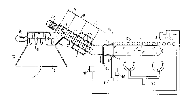
This drawing shows a supply vat 7 which is filled in
the direction of the arrow with large pieces of meat or
ham parts. In the base region of the supply vat 7 there
is located a supply device in the form of a transport
screw 14 which is driven by a motor 16.
The screw compartments of a screw 1 belonging to a
screw conveyor are charged via the outlet opening 15 of
the supply vat 7. The screw 1 is driven by a motor 17
and is journalled in a housing 2. The screw conveyor
comprising screw 1, housing 2 and motor 17 has a
charging section A, a precompression section B and a
degassification section C. The housing 2 is provided in
the region of the degassification section C with
apertures 5 by which the inner space of the housing
~0~7846
communicates in this region with a vacuum chamber 3
which surrounds a corresponding region of the housing
.
A compression section D and a separating device 12
follow the degassification section C of the screw
conveyor. The separating device is formed as a slide
gate and can be actuated in the direction of the arrow
via control device 18 which stands in communication
with a sensor 10.
After the separating device the sleeve or yut to be
filled is fitted onto the housing 2. In this region a
control device 8, 19 is provided for the controlled
withdrawal of the sleeve or gut 9 to be filled. This
control device has a hose 8 which extends in ring-like
manner ovex the outer periphery of the housing 2, with
the sleeve or gut 9 to be extracted being guided
between the hose 8 and the housing 2. The filling
pressure of the hose is regulatable via a control unit
19 and an enlargement of the filling pressure brings
about a greater pressure of the hose 8 on the housing
2, and thus also on the sleeve 9 which is guided
between the hose 8 and the housing 2. As the withdrawal
of the sleeve 9 to be filled from the housing is made
more difficult with an increase of the filling pressure
of the hose 8, a pressure can be built up during
filling in the region of the compression section D
opposite to the filling direction, and ultimately
ensures a dense]y and tightly packed meat or sausage
~roduct.
A closing device is located behind the separating unit
and comprises a mechanical closure unit 13 and the
control unit 20 which is connected to a sensor 11. A
roller track 21l along which the filled sleeve or
filled gut 4 is moved, follows the closing device. A
20~78~
--8--
grasper 22 for picklng up the finished sausage or meat
products from the filling machine is located above the
roller track 21.
In the operation of the filling machine of the
invention the supply vat 7 is filled with filling
material in the form of large pieces of meat or ham.
The motors 16 and 17 which drive both conveyors 14 and
1 run continuously, with the screw l~ transporting the
filling material out of the supply vat 7 via the
discharge opening 15 to the charging section A of the
screw 1. From the charging section A the Eilling
material passes to the precompression section B of the
screw 1 where it is compressed in such a way that the
charging section A is essentially separated in vacuum-
tight manner from the degassification section C
following the precompression section B.
In the degassification section C the air which is
present between the individual parts of the ~illing
material is sucked away by means of the vacuum chamber
3 through the apertures 5 in the housing wall.
The filling material i5 subsequently compressed in the
region of the co~.pression section D and is subsequently
transported past the separating unit 12, 18, the
control device 8, 19 and the closing device 13, 11, 20
into the sleeve 4. The control device 8, 19 which
prevents the withdrawal of the sleeve 9 threaded onto
the housing 2 ensures that the sleeve can only be
withdrawn by applying a force which is produced in
accordance with the advance of the screw conveyor and
acts in the filling direction. The interplay of the
feed force and of the holding force which counteracts
itr and which is brought about by the control device 8,
19 ensures that the individual pieces of the ~iIling
:
~7~
material lie compactly against one another in the
fille~ sleeve and thus that a firm filling of the
slee~e is achieved.
When the front end of the filled sleeve 4 reaches the
sensor 10 the slide gate 12 is moved into the housing
via the control device 18 and is subsequently withdrawn
again in order that the filling material or product
unit which is to be ~illed can be separated from the
subsequent product unit. That is to say the slide gate
12 effectively cuts throuyh coarse pieces of meat
located beneath it and is then immediately withdrawn
again so that the screw 1 can continue to press the
meat product into the sleeve 9.
When this separating position which is provided by the
slider 12 has mo~ed during the filling process, which
is continuously taking place, up to the closing device
11, 20, 13, then the end of the filled sleeve 4 is
located at the level of the sensor 11. The sensor 11
senses the front end of the filled sleeve and as a
consequence actuates the closing unit 13 via the
control unit 20. This is possible since the spacing
between the slider 12 and the closing unit 13 is
simultaneously the same as the spacing of the two
sensors 10, 11, whereby it is ensured that a closing of
the sleeve takes place precisely when the separating
position provided by the slider 12, i.e. the rear end
of the sausage or filled sleeve is located precisely at
the level of the closing unit 13. Because the meat
product, and in particular the chunks of meat, has
(have) been cut through by the slide gate, the closing
device is able to neatly separate one sausage unit from
the next without tearing or crushing of the chunks of
meat.
2~7~4~
--10--
The sensors 10 and 11 can be any convenient sort of
sensor such as an inductive or capacitive sensor.
Alternatively the sensors 10, 11 can be realised as
light barriers. In the latter case the sensors 10 and
11 shown in Fig. 1 can be thought of as light receivers
adapted to receive light from respective liyht sources
provided on the opposite side of the sausage from the
receivers themselves.
During a closing process carried out by the closing
unit 13 both the rear end of the sleeve of a completed
filled product unit and also the front end of the
sleeve of the subse~uent product unit which is still to
be filled is closed.
A knife and/or a pair of clamping devices can be
integrated into the closing unit 13 to separate the
rear end of the sausage such as has just been completed
from the front end of the next sausage to be completed
while preserving the closed state of both the rear end
of the front sausage and the front end of the next
sausage. When using a knife and two clamping devices
(not shown) the knife cuts the sleeve between the two
clamped positions. The clamping devices can also be
designed to secure two wire clamps around the sleeve at
the rear end of the front sausage and at the front end
of the next sausage respectively, such wire clamps
being known per se.
After termination of a closing process the finished
product is removed from the roller track 21 by means of
a grasper 21.
Various possible modifications of the invention will
now be described in more detail with reference to the
further drawings. First of all Fig. 2 shows a schematic
longitudinal section through an alternative design of
20~7~6
screw conveyor of Fig. 1 in which the screw conveyor
has a smaller volume in the region of the
precompression section B than in the region of the
charging section A. This is achieved in that both the
screw and the housing have a constant cylindrical shape
but the screw has a smaller pitch in the region of the
precompression section B than in the region of the
charging section A. Because of the smaller pitch the
material must necessarily be compressed on passing from
the charging section A to the precompression section B.
That is to say in this embodiment the screw
compartments in the region B have a smaller volume in
the precompression section B than in the charging
section A. It can also be seen from Fig. 2 that the
pitch of the screw conveyor 1 in the degassification
section C is increased again, i.e. the individual screw
compartments are of larger volume in the region of the
degassification section C than in the region of the
precompression section B.
Moreover, it can be seen from this figure that the
screw compartments which follow the degassification
section C have a smaller volume than the screw
compartments in the region of the degassification
section C. This effectively prevents the filling
pressure generated in section D from acting backwards
on the degassification device.
Fig. 3 shows another modified screw conveyor suitable
for use in the filling machine of Fig. 1 with the screw
1 having, in the present case, a smaller diameter in
the region of the precompression section B than in the
region of the charging section A. In this case the
screw 1 in fact has a smaller pitch and a smaller
diameter in the region of the precompression section B
than in tha region of the charging section A. It will
2~5784~
-12-
be noted that the screw compartments again have a
larger volume in the region of the degassification
section C than in the region of the precompression
section B.
Fig. 4 is a schematic longitudinal cross-sectional view
through the degassification section C of a shaft of a
screw conveyor such as that shown in Figs. 1, 2 or 3,
however, in this drawing the flights of the screw have
been omitted for the sake of clarity. In any event ~ig.
4 shows the apertures in the hollow shaft of the screw
1 and also shows schematically a vacuum source 24
connected to the interior of the hollow shaft.
In contrast Fig. 5 shows a degassification device 25
suitable for use with the screw conveyor of Fig. 1 (or
also in any of the other figures) in which the
degassification device 25 has a vacuum chamber similar
to the vacuum chamber 3 of Fig. 1, but with a drain 26
at its lowermost point which communicates via a tube 27
with the flow of material which will enter the screw
conveyor from the vat. Thus liquid and meat remnants
which collect at the bottom of the vacuum chamber or
degassification device of the screw conveyor, and which
enter the drain region 26 are fed back to the inlet to
the screw conveyor. Here the liquid and meat remnants
are re-incorporated into the meat filling for the
sausage by the mixing action of the screw conveyor.
Thus 27 forms a return line from the degassification
device 25 to the supply vat 7.
Fig. 6 shows a longitudinal axial section through a
screw conveyor which can also be used in the filling
machine of Fig. 1. It will be noted that the screw is
journalled in a shaft bearing 28 provided at the drive
side and is furthermore journalled in guide rings 29
provided at the inner wall of the housing. The guide
20~7846
-13-
rings 29 are matched to the shape of the inner wall of
the housing and distributed around its periphery, they
each extend over the axial length of at least one screw
compartment. The inner side of the housing formed by
the guide rings or elements 29 is so laid out that
rotational movement of the pieces of meat to be
transported is counteracted and the movement of the
pieces of meat in the transport direction is promoted.
This can ~or example be done by ensuring that a larger
frictional force acts between the inner side of the
housing, i.e. the inside of the guide elements 29 and
the pieces of meat to be transported then acts between
the screw and the pieces of meat to be transported.
This can be done for example by the provision of small
flutes or splines at the inner side of the housing,
i.e. at the inner side of the guide elements 29.
Even without the provision of guide elements such as 29
it is expedient to provide splines, in particular small
male splines, in the sidewall of the housing as is
illustrated by the further Figs. 7 to 11. More
specifically Figs. 7 and 8 show the provision of
axially directed straight male splines 30 on the inner
wall of the housing. Fig. 7 in fact shows a perspective
view of the outer side of the housing and the male
splines 30 are shown here in broken lines because they
are not visible from the outside of the housing. The
position of the male splines 30 can however be seen
from the cross-section of Fig. 8.
Fig. 9 shows that the male splines, here designated
with reference numeral 31 can take the form of helical
male splines resembling gunbarrel rifling.
Fig. lO illustrates a different form of the male
splines, here the male splines 32 are straight but are
interrupted by non-splined regions 33.
20~784~
-14-
In Fig. 11 it will be seen that the male splines 30
(for example the male splines of Fig. 7) cross the
apertures provided in the wall of the degassification
section C, such as the aperture 34, and thus form a
sieve or screen which effectively prevents large pieces
of meat passing through the apertures. This facilitates
the degassification of the meat product passing through
the degassification section. That is to say, in Fig. 11
the male splines 30 are led in the region of the
degassification section C at the inner side of the
housing in front of apertures 34 in the housing wall,
whereby a sieve-like device arises.
Finally, Fig. 12 shows how a deflector 35, which could
indeed be a deflector of variable length or angle is
provided between the transport screw 14 and the screw 1
of the screw conveyor to prevent overfilling of the
first screw compartment of the screw conveyor.