Note : Les descriptions sont présentées dans la langue officielle dans laquelle elles ont été soumises.
WO91/15351 PCT/GB91/00521
Ç~ ,
BAGGING ARRANGEMENT FOR SYNTHETIC
RESIN COMPONENT PROCESSING APPARATUS
The present invention relates to synthetic resin
component processing apparatus and is particularly
although not exclusively concerned with apparatus for
curing and/or moulding synthetic resin composites in the
production oP components.
Vacuum bag moulding is currently employed for the
mouldin~ of complex components which cannot be made
practically by other forms of moulding such as
compression moulding. For the moulclincJ process, layer~
o~ composite ~aterial which m~ke up the component are
laid up on a componen~ ~upport in required r~la~ve
di~po~itlons. A bagcJincJ blank~t o~ a ~laxiblQ m~terL~l
ls placed over thc a~embly Oe layer~ ~ormin~ th~
component and extend~ ~aro~s the component support
against which it is sealed along the edges of the
support. A vacuum is then applied with air being
j withdrawn Xrom beneath the bag and the component assembly
is then subjected to any one of a variety of processing
' cycles, for example by curing in an oven (heat and vacuum induced atmospheric pressure only) or an autoclave (heat,
pressure and in certain cases vacuum induced atmospheric
pressure), dependent upon the resin materials being used.
After treatment, the vacuum is released. The bagging
blanket is then removed and the processed component
replaced by a further component to be processed. The
- processed component may then be subjected to any required
post curing treatment.
.
It will be appreaiated that the baqging blankot mu~t be
arranged to ~orm with the aomponenk support an e~ective
~aal around the periphery o~ the support to enable an
effective vacuum environment to be obtained and to
: SUB~liivl~ 5~
:~ ` ".: . ~ `,. , .: . ` . .. . . `
~ WO91/15351 PCT/GB91/00521
~ .. ,l~R~
, 2
prevent the ingress of air as a result of atmospheric
pressure and any pneumatic pressure applied to the
' assembly during an autoclave cycle and various techniques
have been employed to achieve these ends.
,',
In prior US patent No 4664737 it has been proposed to
provide an upstanding sealing edge around the periphery
', o~ the componer1t support and to br.ing the baggi~g blanket
under tenslon over the s~liny edge. The blanket of the
prior proposal is provided with a skirt in the form of a
,; net attached to and extending around the periphery of the
blanket and a plurality of outstanding spaced pins are
provided on the support so that when the blanket is
i placed over the component ~nd the component support with
the net hanging down ak thc periphary, the blanket can bc
tensioned by pullln~ the net ovQr the ~ree end~ Oe
i~ appropriate p~n~ and th~ ten~lon ~ub~ectuent.ly acl~u~t~d 1
necessary by repo~.itlonln~ oE the net on the pl~ Wlth
~ the blanket so tens.toned, an e~ct:lve initial seal i5
;, provided ~etween the ~e~liny edye on the support and the
blanket. When air is withdrawn ~rom beneath the blanket
the pressure o~ atmospheric air on the blanket increases
the seal between the blanket and sealing edge and
,~ provides the main sealing action.
It is an object of the present invention to provide a
~, bagging blanket for use with a synthetic resin component
processing apparatus which uses means alternative to a
` net for tensioning and positioning the blanket.
`~ According to the present invention, there is provided
component processing apparatus comprising a component
support on which a component is mounted and on which is
formed at or in the reyion o~ its periphery a sealing
edge extendin~f around th~ p~riphery o~ ~he support, ancl a
bagging arrangemen~ for use with the support comprising a
, collapsible bagging blanket which in use is extended ` ~.
.,~
, WO91/15351 ~ ZC58~ PCT/GB91/00521
, 3
across the component and the component support and which
is tension~d to bring it into engagement with the sealing
edge on the support, characterised by the fact that the
component support is re-entrant beyond the sealing edge
to form a re-entrant zone and that the blanket is so
formed as to receive and receives at its periphery draw
means by which the e~ective length o~ the blanket
periphery can be varied Prom an extended length which
allows the blanket to be placed over the component and
the component support and into a covering disposition in
which it covers the component and the component support
and in which the blanket periphery extends beyond the
sealing edge on the component support to A reduaed length
which in the covering disposition o~ the blanket brinc3s
~ the blanket periphery into the re-entran-t zona and the
;~ blanket again~t the sealing ed~e on the component
support.
In a ~irst embodiment of the invention hereinafter to be
de~cribed, the draw means permits the blanket periphery
to maintain its extended length and is contractible to
bring the blanket periphery to its reduced length.
Pre~erably, the draw means comprises an elongate draw
element which is received by the blanket along the full
~, periphery of the blanket.
In a specific embodiment of the invention hereinafter to
, be described, the draw element is exposed at one or more
predetermlned exposed locations along the periphery of
the blanket and the predetermined exposed location or one
or more of the predetermined exposed locations i~s
utilised as a draw location at which the e~fective length
of the draw element can be reduced. O~her expo~ed
loaations may be u~ efl ~o provide access ~or
ancilliary equipment required Por the cure assembly, such
or example as vacuum lines and thermocouple leads.
;T~ 1 VTE !~;E~
. ~; .~ . , ` ` .` ;; . ~ . . . . , . . ; `
~.',1 : ` ; ' .' , `. ,, , .' ; ` ' : ' . ' .
WO 91/15351 .; , . ; -S-:' ' PCI/GB91/00521
ZOS~2?~
The draw ele~ent may, if desired, be secured to the
blanket at securing locations along the blan~et periphery
whereby a reduction in the effective length of the draw
element at a draw location produces a local reduction in
the length of the blanket periphery.
,;'. .
In a specific embodiment of the invention hereinafter to
f be described, the periphery of the blanket is ~olded bac~
on itsel~ and so secured as to provide a passageway for
the draw element through which the draw element passes
and the periphery of the blanket is cut away at the
exposed location or locations to expose the draw element.
Where a plurality o~ draw locations are provided, they
may ~urthermore be so arranyed in spaced relation aro~lnd
the periphery o~ the blanket that reduction ln tha len~th
o~ the draw elemcnk can be made to provicle ~n oven
~en~ionincJ o~ the b.lankot over th~ ~omponont and ~h~
component ~upport.
In a specl~ic embodiment o~ the invention hereinafter to
be described, there is provided at a draw location a draw
device, through which the draw element passes to ~orm an
open loop at the draw location and which includes loop
enlarging means whereby the loop can be enlarged to
reduce the effective length of the draw element. The
draw device may conveniently comprise a support plate and
the loop enlarging means may comprise a plurality of
spaced pins extending away from one side of the plate.
j The draw element is then arranged to pass along the plate
in a plane parallel to the plate so that it can be
withdrawn on the side of the plate carrying the pins and
formed into a loop by passage round one or more of the
pins.
In a ~urther speai~ia embodiment o~ the inventlon
hereinafter to be described, the draw device may comprise
?
- WO91/l535l PCT/GB91/0052l
i8;~89
..; .s
one or more guide elements for forming the draw element
into a loop and the loop enlarging means may comprise a
member movable from a first predetermined disposition
relative to the guide element or elements to a second
predetermined disposition relative to the guide element
or elements. The draw element is then arranged to pass
through the guide element or elements to form a loop and
the movable member is arranged to engage the loop to
cause the loop to enlarge by movement oE the movable
member ~rom the first predetermined disposition to the
second predetermined disposition. The movable member may
advantageously include resilient means for moving it from
the ~irst predetermined position to the ~econd
predetermined po~ition.
~n the ~ir~t embodiment o~ kh~ Lnvcntlon h~reinhe~ore
re~erred to, the draw ~lem~nt m~y a.l~ernatively b@ Op~fl
ended With the oppo~te ~nd~ th~roo~ located a~ a draw
location where they can be drawn toyether in a tying
operation to reduce khe e~ective length of the draw
element.
In a second embodiment o~ the invention hereinafter to be
described, the draw means maintains the blanket periphery
at a reduced length and is extensible to permit the
blanket periphery to extend to its extended length.
,....
In the second embodiment of the invention hereinbefore
referred to, the draw means may comprise an inextensible
portion in the form of an elongate draw element of
` inextensible material, and an extensible portion, such as
; a sprlng, connected thereto. The draw means may
; alternatively comprise an elongate draw element oP an
'~ inextensible mate~ial and the extensibla portion ~ay th~n
comprise a loop o~ the draw element which is biased by a
` spring into a reserve loop and which is released against
;i the action o~ the spring to extend the ef~ective length
.` SUESTITU~_ SHE~T
., ~ ' ` . . .. `.. ` . . ` . ~ . ` , ... ., . , . `
WO91/153~1 PCT/GB91/00521
,, 6
of the draw element.
In yet another embodiment of the invention hereinafter to
be described the draw element is open ended with the
opposite ends thereof located at a draw location where
they can be held in fixed relation by attachment to the
component ~upport. The effective length of the draw
elem~nt may be ~educed by means o~ a draw device at the
draw location.
In the embodiments of the invention hereinafter to be
described the sealing edge is provided by a sealing
member extending continuously around the component
support at or in the r~gion o~ the periphery Oe tho
support. The ~ealing member is pre~er~bly o~ tri~ngular
cros~-~cction with a bn~e thorQo~ yas-tight bond~d ~o thQ
~upport and wlth ~n opposlta ap~x provlcl.LncJ a 3~lin~J
odge ups~andiny rrom tho ~upport to prov.Ldc an lnl~lal
~eal betwe~n the blankct and the support, with the main
seal being provided as a slick seal along the inside
incllned ~ace o~ the sealing member.
The component structure may conveniently take the form of
a flat table top supported by a sub-structure in such a
way that the edges of the top extend beyond the
sub-structure to provide the re-entrant zone. .~--
Embodiments of the invention will now be described by way
of example with reference to the accompanying drawings in
which:-
Fig l is a schematic perspective view of a companentprocessing apparatus according to a first embodiment of
the invention, with some par~s cut away,
Fig 2 is a schematic cross-section of a part only of the
apparatus shown in Fig l,
~iUE~;TIT~TE~ S~E T
-`` ;` ` .. ,. ,.. ". . . ........ ... .. ..
. .,.. ,,. .. ~,. ;,. `~ ., ...... . ; , : `
. : , ., . `,: :. ~ `, . ': ' , , .: ` ' ' ~ ` :.... -
... .. . . . .. . ..
WO 91/153~ PCT/GB91/00521
~ 2~58~89
Figs 3, 4 and 5 are schematic views illustrating the way
in which the blanket shown in Fig 1 is provided with a
skirt portion which is folded back upon itself to form a
passageway for a draw element for the blanket,
Fig 6 is a schematic perspective view of the blanket
shown in Figs 1 to 5, illustrating a plurality of draw
locations where the draw ele-~ent ~or the blanket is
~xposed to provid~ ~or local ten~ionincJ of the blanket.
Fig 7 is a schematic scrap side elevation of a bagging
blanket of the form shown in Fig 6, except insofar that
the draw element is secured to the skirt portion of the
blanket at locations between the draw locations,
Fig ~ ls a ~ch~matic 5crap vi~w o~ a slmplo kcnsionlng
device ~or u~o at draw locatlons o~ khe bl~nk~t
illustrat~d ln Flg 7,
Figs 9 and 10 are s~hematic cross-sections taken on the
lines X-X and Y-Y in Fig 3 revealing the completed bond
between the blanket body portion and the skirt portion,
Fig 11 is an exploded schematic perspective view
illustrating an alternative attachment procédure for -
attaching the skirt portion to the blanket periphery,
Fig 12 is a schematic cross-section taken on the line Z-z
in Fig ll, illustrating the completed bond between the
blanket body portion and the skirt portion,
. . .
Fig 13 is a schematic perspective view of a preferred
tensioning device ~or use at a draw location of khe
blanket,
Fig 1~ is a schematlc elevation o~ the tensioning device
shown in Fig 13, illustrating alternative paths ~or the
~' U ~ "~, T ~
:, ,:
WO91/15351 ~58Z~ PCT/GBg1/00521
draw element around the pins of the device,
Fig 15 is a schematic perspective, scrap view of the
blanket and component support illustrated in Fig 1,
showing a corner location and a side draw location,
Figs 16 and 17 are schematic scrap sections of the
blanket and component support ~hown in Fi~ 1, taken on
the lines X-X and Y-~ in Fig 15,
Figs 18 and 19; 20 and 21; 22 and 23; 24 and 25; and 26
and 27 are schematic views of further alternative
tensioning dev.ices ~or use at draw locations o~ the
blanket illustrated in Fig 1,
Fig 28 i~ a schcmAtlc per~pactive viaw Oe a ten~lon.Ln~
devlce for pretcn~lonlnc3 a draw el~m~nt ~or u~ ln a
~econd embodiment Oe the in-v~ntlon,
Fig 29 is a schematic scrap section of a part of the
device shown in Fig 28,
Figs 30 and 31 are schematic scrap views of further `.
alternative tensioning devices for use in the second : '
embodiment of the invention,
Figs 32 and 33 are schematic serap views of adjustment
devices for adjusting the length of the draw element used
in the second embodiment of the invention,
Figure 34 is a schematic side elevation of part o~ a
component processing apparatus of the form shown ;ln Fig
1, except insofar that the draw element is open ended and
the ends thereo~ are attached to the component ~upport,
Fig 35 is a schematic perspective view of a simple
attachment and ~ensioning device for use at the draw
SUB~T~TUTE S~$~`.~'`'i
WO 91tlS351 ,~89 PCI/GB91/00521
~"~
locatio~ of the blanket illustrated in Fig 34.
Fig 36 is a schematic perspective view of a device which
enables the draw element to be tensioned by attaching
only one free end of the~draw element to the component
support,
Fig 37 is a ~chematic elevatlon o~ part of the apparatus
shown in Fig 1, except insofar that one free end of the
draw element is attached to the component support by
means of the devices illustrated in Figs 35 and 36, and
Fig 3~ is a ~chematic side elevation of part o~ a
component support suitable ~or use wlth the bagginc3
arrangements illustrate~ in Fig~ 3~ and 37.
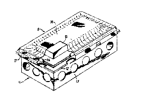
Re~erring ~lr~t ~o FlcJ 1, a c:ompon~nt proao~ln~
apparatu~ is shown ¢ompri~lnc~ a component ~upport :Lay-up
5tructure 11 including a Plat component ~upport plate 12
supportcd by a base 13. The component support plat~ 1~
carries in the region o~ its periphery a sealin~ member
14 which extends fully around the plate 12 but which is
shown partly cut away in Fig 1. A component 15 for
processing is mounted on the support plate 12 within the .
bounds of the sealing member 14. A blanket 8 also shown
partly cut away includes a body portion 16 which is
spread over the component 15 and the entire surface of
the support plate 12 and a skirt portion 17 which extends .
over the edges of the four sides of the support plate 12.
. .
As best seen in Fig 2, the blanket body portion 16 drapes
over the sealing member 14 and the skirt portion 17 o~
th~ blanket extends over the ed~e o~ the ~upport plat~ 12
along all ~our sides o~ the plate 1~. As 9hown in Fig 2,
the skirt portion ~7 is ~olded back upon itself to form a
passageway 18 extending for the ~ull length o~ the
blanket periphery ~or reception o~ a draw elcment 1~.
,, ,
SUESTITUT- S~ T
". ' .. ` .~.. ` ' ` .: . .. .. ` .` ` ` ; ' ` .
WO91/15351 ,~ 2~ PCT/GB91~00521
... ~ ~
The draw element 19 can be tensioned in a manner
hereinafter to be described to draw the skirt portion 17
beneath the support plate 12 and into a re-entrant zone
10 formed by the projection of the support plate 12
beyond the base 13 which supports it.
The blanket body portion 16 may be made from any one of
the variety of cli~erent materials and i5 prefer~bly made
from an el~tomeric matcrial, yivinc3 it hic3h tensile
strength, the ability to stretch and retract rapidly with
full recovery to its original dimensions and good tear
resistance. The skirt portion 17 may also be made from
any one of a large number of fabrics provided they are
tear re~i~tant and both drapeable and ~lexible. Xt may
~urkhermore be o~ ~ny weave provided lt can be stitched
and mu~t be re~istant to continuou~ ui~o at the
temperA~urc~ to bo u~cl ln tho proce~sln~J Oe ~h~ -
component. Suitabl@ yarn~ ~or th~ materlal ~ormlncJ ~he
ekirt portion 17 are aromatla polyamide~ such ag Nornex
and Kevlar (Registered Trade Marks), oxidised
polyacrylonitrile ~PAN), ~ibreglass, linen, nylon and
polyester. The yarn for st~tching must have a hl~h
tensile strength and resistance to heat and abrasion eg
Kevlar or a polyester.
The draw element 19 may be in the form of a rope and
manufactured from any of a variety of materials provided
it is flexible, heat resistant and has a high breaking
strain. Such materials include Nomex, nylon
(multi-filament or mono-filament), Kevlar, steel
cable/chain or specially reinforced solid rubber/hollow
hose, for example, in silicone, and may be even ~ome form
of belting/strapping in any materials.
Re~erring now to Figs 3 to 5, the skirt portion ~7 may be
secured to the periphery of the blanket body portion 16
by arranging for perforations 20 in the skirt portion 17
g~l~3STlTUTE SWF.~T
:. ", `
.
~, . . . `: ' :
W09l/l535l PCT/GB91/00521
5~3289
11
and securing it to the periphery of the blanket 16 by
bonding using a honding strip 21 as shown. The skirt
portion 17 is, as shown, then folded back on itself to
form a double ply edge 22 shown in Fig 5, which is then
double stitched to the main body of the skirt portion 17
to form the passageway 18.
The blanket 8 illustrated in Fig 1, 2 is also shown in
Fig 6, ~rom which it will be seen more clearly that t~e
~kirt portion 17 is cu~ away ~t dr~w locations 22 and 23
along one side of the blanket and at a draw location 24
along an adjacent side of the blanket.
Additionally, the skirt portion 17 on the side remote
~rom ~he draw locations 22 and 23 i~ similarly cut away
at corresponding draw location~, while a ~urth~r draw
location is provided on th~ ~ldo Oe the bl~nk~k oppo~ite
the draw locAtlon 2~. Furthermor~3, th~ ~klrt portlon ~7
iY interruptQd ak corn~r loc~t.Lon~ 2~, ~6, 27 a~fl 2fl ~.o
~acllitate th~ draping Oe ~he ~klrt portion 17 over the
edge~ o~ the support plate 12.
In th~ embodiment o~ the invention shown in Fig 6, the
draw element 19 is shown threaded through the passageways
18 formed in the skirt portion 17, with the two ~ree ends
appearing at the corner location 25. With this
arrangement, the blanket 16 is placedl as shown in Fig 1,
over the component 15 and the support plate 12 and the
free ends of the draw element 19 drawn together and
secured to bring the skirt portion under the support
plate 12 as shown in Fig 2. Tensioning devices
hereinafter to be described are then used at the draw
locations along the sides of the blanket 16 to provide a
full and even tensioning of the blanket 16 so that it
bears down in sealing contact with the sealing m~mber 1
~or i~5 ~Ull ex~ent around the poriphery o~ the support
plate 12. The draw element 19 may be made from any
SUE~TiT T ~~ T
'i: ' :, ', , . . . ' ` . , ., .'. ' ' . ' I : ', . `, ' , ' I : .
~ Z ~ ,8 ~X ~ pCT/~B9l/0052l
material which can withstand the treatment/cure
environment and may range from steel to a lightweight
composite.
In an alternative embodiment of the invention illustrated
in Fig 7, the draw element 19 is held captive in sections
of the passageway 18 at locations 29 between adjacent
draw locations so that when the draw element 19 is
tensioned at an intermediate location, s~y location 30, .
~he tensioning effect on the blanket 16 is localised. In
this way localised adjustments of the tensioning of the
blan~et 16 can be made simply by adjustment of individual
~ensioning devices at the di~ferent draw locations. A
simple ~orm o~ tensioning device i5 illustrated in Fig 8
and comprises a collar 31 through which th~ draw clamant
l9 ig pas~ed to produce a loop 3~, the drnw el~mQnt 19
being increa~ingly t~n~.Lon~d by drawin~ more o~ thQ draw
element 19 throuyh the ~oll~r 31. Thl~ slmpl~ dQvic~ h~s
the ~eature that the draw cl~ment 19 can be easily
tensioned and quickly released.
The attachment o~ the sklrt portion 17 to the blanket
body portion 16 as illustrated in Fig 3 produces a secure
bond as illustrated in Figs 9 and 10, with the blanket
body portion 16, the skirt 17 and the bonding strip 21
being bonded together using an elastomeric sealant or
adhesive 33. Alternatively, attachment of the skirt
portion 17 to the blanket body portion 16 may be achieved
as illustrated in Figs ll and 12 where an additio.nal
reinforcing strip 9 of an elastomeric material is
interposed between the outer strip 2} and the bla~ket
body portion 16, with the end o~ the skirt portion 17
being arr~nged to pass over it and to be folded back
against the lower ~ace o~ it to ~orm a secure attachment
when the assembly i9 bonded together by the sealant 33.
Referring now to Fig 13, a tensioning device 3~ is shown
SlJBSTlTlJTE SI~EE~
WO 91/15351 ~582,~t '- PCltC;B91/00521
i, .,: ;.. ~ - ' .
13
which comprises a flat plate 35 carrying a plurality of
spaced pins 36 secured to the plate and extending from
one face thereof. The plate 35 has also secured to it
guide plate 136 mounted on pillars 37 which space
vertical portions of the guide plate 136 ~rom the face of
the plate 35 and space the horizontal top portion of the
guide plate 136 from the upper edge of the plate 3S.
In use, the device 3~ shown in ~ig 13 is presented to the
draw element 19 at a draw location o~ the blanket body
portion 16 so that the draw element 19 engages under the
guide plate 136 and can then be pulled down over the
~ront ~ace o~ the pl~ta 35 and pas~2d in a loop around
one or more oe the pins 36 thereby tensioning the draw
element 19 ~t the draw location. As be~t sc~n ln F,l~
the draw element 19 c~n b~ arran~d to takQ any ona o~ ~
number o~ path~ arouncl th~ pLn~ 36 to provLd~ ~or a wiclQ
range o~ loop~ o~ dl~rcrent ~lzo~ to permit adjustm~nt of
the ten~ion in the draw element 19.
The plate 35 and the pins 36 may bc manu~actured ~rom a
number o~ materials eg. steel, aluminium, rein~orced
nylons etc ie. any material able to withstand the cure
cycle and exhibit the required mechanical properties.
As best seen in Fig 15, the skirt portion 17 of the
blanket is arranged to be cut away at corner locations of
the blanket and a corner-pie~e 161, preferably of
elastomeric material, is inserted to fill the cut away
corner locations to enable proper seating of the blanket
body portion over the support plate 12 and even
tensioning of the blanket body portion over the sealing
member 14. As will be seen ~rom Fig 16, the edge o~ the
blanket at the corner locations is strengthened by a
rein~orcing strip 38 which is bonded to the blanket using
an elastomeric adhesive.
~ .
!3 u~ Tur~ $~EET
,; , . ,. , .. ., . .,.,` . ` . . . . . , ~ .. ~ .
WO91/15351 ,. . ~ ,;;. PCT/GB91/00521
z(~5~2~39 ~
14
A variety of different tensioning devices for tensioning
the draw element l9 will now be described with reference
to Figs 18 to 27. All require the draw element 19 to
pass in the for~ of an open loop through the device and
provide means for extending the length of the loop to
draw in the draw element 19 and reduce its length at the
appropriate draw loc~tion o~ the blan~et, thereby
brinqing the element l9 under tension so that it is dra~Jn
into the re-entrant zone lO beneath the support plate 12
as shown in Fig 2.
In Figs 18 and l9, it will be seen that the tensioning
device shown compri~es a body portion ~0 with two
dcpending arms ~l and 42 which are ~pac~d apart as ~hown
and are joined toqeth@r ~t their lower ends by a b~.Lc1cJe
pieCQ ~3. The hody portlon ~0 includQ bor~s ~ and ~5
and ln u~o o~ thQ d~vla~ the dr~w ~ n~nt l9 i~3 arranged
to pa~ down through thQ bor~ ~1, ro-lncl the brlclcJ~ P1QC~
~3 and then back up throuqh the bore ~5 to ~orm an open
looy. As shown in Fig l9, the device further includes a
pivotal arm ~6 which can be turned by a handle ~7 through
a qulck release ratchet mechanism ~not shown) from a
position shown in Fig 18 in which it lies within the
bounds of the plates 4l and 42 and parallel thereto up to
a position at right angles thereto as illustrated in Fig
l9. The loop in the draw element l9 formed in the device
can thus be enlarged by turning the handle 47, thereby
reducing the effective length of the draw element and
bringing it under the tension required to hold the
blanket in place on the support plate 12 and to provide
an initial seal, between the blanket and the seal:ing
member 14.
In the tensioning device lllust~a~ed in Flg ~0 and ~l,
the draw elemen~ lg is arranged to pas~ through an
opening 48 at one side of a body portion ~9 o~ the
device, ~hen pass along a channel 50 on the end o~ a
.
WO 91/15351 2~58289 ~CT/GB91/00521
f~s r~
dlsplaceable arm 51 pivoted at 52 on the main body
portion 49 and then upwardly through a further openlng 59
formed on the other side of the body portion 49. The arm
51 is resiliently biased by a spring 53 away from the
body portion 49 of the device. The draw element 19 is
thus reduced in length at the draw location by the
~ormation Oe the loop within the device ancl t~nsioned by
the biasincJ action of the plvotal arm 51.
A further alternative tensioning device is illustrated in
Figs 22 and 23 and comprises an arm 5q having a boss 55
pivotal on a sha~t 56 which carries at its ends collars
57 and 58 through which tho drAw element 19 i5 passecl as
shown. The arm 5~ i5 extended by a screw-threaded ~ha~t
59 carrying a shoe 60 havinc3 a chanllel G1 and the clr~w
clemcnt 19 i9 as shown .Ln r~'.iCJ 23, arr~nyocl to p~ss ~rom
the collar 57 throuqh the chanrlal 6~ and back throucJh the
collar 5R, A reduction in th@ @~ect1v@ length oE the
draw element 19 is then achieved by the provision of the
loop within the device, which can be set by an
~ppropriate axial adjustment o~ the sha~t 59 which is
s~rewed into the arm 54.
The tensioning device illustrated in Figs 24 and 25 is of
the same general form as that shown in Figs 22 and 23,
except insofar as the boss 55 is replaced by a yoke 62
which is pivotal on the shaft 56 carrying the collars 57
and 58. The tensioning arm 54 can then be removed from -
the shaft 56 to release the draw element 19 and be
repositioned when further tensioning of the draw element
is required.
The tensioning arm 54 o~ the device shown in Figs 24 and
25 may .i~ desir2d be replaced by a modi~ied tensioning
arm 54' shown in Figs 26 and 27. In this modification a
shoe portion 64 is adjustably threaded on the end o~ a
sha~t ~5, a head 6~ o~ which i5 slidabl~ arranged within
.~
T l~ T ~ T
'; ~,i, . , ' ` ' !: , I ~ , ~
Wo91/15351 ~, , ,t PCl/GB91/00521
ZQ58289 ~ `
;. . .
16
a counterbore 67 in the arm 54~, which also encloses a ~ :
biasing spring 68 which nor~ally holds the shaft 6~ in
the position shown in Fig 26. such spring loading of the
shoe portion 64 enables the arm 54' carrying the yoke 62
to be displaced along the shaft 6~ effectively to shorten
the tensioning arm and facilitate removal of the arm from
~he support shaft 56.
In a second embodiment o~ the invention now to be
described, the skirt portion 17 o~ the blanket carries a
dràw element l9 which is pretensioned to draw the
periphery o~ the skirt portion 17 into the re-entrant
zone lO and beneath the support plate 12 as shown in ~iqs
l and 2 and is exten~ible to enable the skirt portion 17
to be extended to enable it to b~ drawn over th@ 5upport
plate 12 when the blanket body portion 16 is p.l~eafl over
the component 15 ~nd th~ ~upport P1~tQ 1~. The bl~nkQt
with its sklrt portion 17 and ~hQ draw elem@nt 19 may
conveniently take the form described with re~erenc~ to
Figs l to 12, except inso~ar as ~he draw element 15 is
arranged as a continuous element extending ~or the ~ull
periphery of the skirt portion 17 and is formed into a
reserve loop by a tensioning device, which may take any
one of a number of different forms, three of which are
illustrated in Figs 28 and 29, Fig 30 and Fig 31.
It will be seen from Figs 28 and 29 that the draw element
l9 is arranged to pass over a jockey pulley 69 carried by
a backing plate 70, then beneath and around a plunger 71
and then over. a second jockey pulley 72. As will be seen
from Fig 29, the plunger 71 is carried on a shaPt 7~
having a piston element 74 which rides in a housing 7S
which is closed by a top 76 and which hoUses ~ coil
spring 77, the arrangement being such that the plunger 71
is bia~ed downwardly by the spring 77 ~rom a seated
position on the ~ase oP the housing 75, causing a reserve
loop 78 to be ~ormed in the draw element 19 and bring:in~
.
`; . ~ ` -. . : , ` .: ` ` ~
WO9l/ls3~ c< PCT/GB91/00521
Z(~ 289
s~~
.......
17
the draw element 19 under tension so that with the skirt
portion 17 of the blanket in position, as shown in Figs 1
and 2 the skirt portion is drawn into the re-entrant zone
beneath the plate 12 and the blanket body portion 16 into
contact with the sealing member 14 on the top plate 12.
The draw element 19 can be lengthened by reducing the
extent o~ the reserve loop 78 against the action of the
~pring 77 and the arrangement is made such that the
extension provided enables the skirt porkion 17 to be
passed over the edge of the top plate 12.
The tensioning device illustrated in Figs 28 and 29
allows not only for the cE~ective lcnythening o~ thc dr~
element 19 but al~o allows ~or adjustment o~ the ac~u~
length oP the element 19 thro~lcJhout thc .LL~e og th~
blanket.
~n alternative ten~onlng d~v.LcQ COE U~e 1n th@ se~oRd
embodiment o~ the invention is illustrated in Fig 30 and
comprises a body 79 which supports leaf springs ~0 ~nd 81
which carry ~ollars a2 and 83. ~n use, the draw el@ment
19 passes through the collar 82, through a channel on the
body 79, across the top of the body 79, then downwardly
through a Purther channel in the body 79 and finally
through the collar 83.
The springs 80 and 81, in the disposition shown in Fig
30, hold the draw element 19 at a reduced length in which
it brings the skirt portion 17 of the blanket into the
re-entrant zone beneath the plate 12 and the body portion
16 of the blanket into engagement with the 5ealing member
14. The placing of the blanket with the skirt porkion 17
extending over the edge oP the plate 12 can then be
a~hieved by extendinq the e~ctive longth o~ the draw
element 19 by Plexing the leaP springs ao and 81
outwardly.
- SUE3STITUTE SHEET
WO91/153;1 Z058Z~9 PCT/GB91/00521
! t~ ,"~ J ~i;,"
18
In yet a further alternative tensioning device
illustrated in Fig 31, the draw element 19 has opposit~
ends connected together by a coil spring 84 which holds
the draw element 19 at a length in which it draws the
skirt portion 17 of the blanket into the re-entrant zone
beneath the support plate 12. The placing of the blanket
on the component 15 with the skirt portion 17 extendinq
over th~ e-.lge o~ the support plate 12 can then be
achieved simply by extension of the coil spring 84.
The two tensioning devices described with reference to
Figs 30 and 31 do not, however, allow for adjustment of
the actual length of the draw element 19 during the liP~
of the blanket and ~djustment devices ~or this purpo~
may be provided a5 illustrated in Fic~s 32 and 33.
Xn the ~mbodiment o~ th~ inv~ntlon .Lllu~.trated ln l;'lg
the ~ree end~ o~ the ~raw e.l@m@nk l9 flppear at draw
loc~tion 90. Each ~ree ~n~ o~ th@ draw elemen~ 19 ie
attached to khe base 13 of the component support by means
o~ a clip 91 which anchors the free end oP the draw
element to the edge o~ an ~ir~low aperture 92 ln the
component support base 13.
Fig 35 illustrates a clip 91 suitable for attaching a
free end of the draw element 19 to the component support
base 13. The clip 91 has a head portion 93 for engaging
the edge of the airflow aperture 92 and a lockable collar
portion 94 which enables the draw element to be further
tensioned when the free end of the draw element is
secured to the component support base 13.
Since most component supports have a base 13 which
incorporate ap~rtures to allow airPlow and ~acilitate
accQss to ~he undorsid~ o~ ~ho compon~nt, ~he free ~nds
of the draw element 19 may be attached to the component
support base 13 by making use of those aperture5, without
..
$l~ TlTlJTE ~HE~E~T
-, ` ` . ` . . `
. .,~, .. .-. ... ..
WO 91/15351 , , 2~S~Z~ PCT/GB91J00521
~ .
19
requiring modification of the component support base 13.
However, under certain circumstances, when suitable sites
are not available in the base 13 of the component
support, the free ends of the draw element 19 may be
anchored to special anchor handles fixed to the component
support base 13.
F'ig 36 .lllustr~tes a dev.ice which allows the draw element
19 to be attached to ~he cornponent support base 13 by
anchor.ing only one of the free ends of the draw element.
A ring 95 is secured to one free end of the draw element
and the other free end of the draw element is passed
through the ring 15.
In the embod.iment Oe the invention lllustrated .in F.L~J 37,
the device lllustra~e~ in ~icJ 3~ i~ securod ko on~ ~ree
~nd o~ th~ dr~w ~lQm~nt 1~ and th@ othor ~r~ ~ncl o~ ~he
draw elemon~ ~ is anahor~tl by m~Ani~ oL' cllp 91 to the
edge oE aperture 92 in thc component isupport base.
Fig 38 illustrates A component support suitable Eor use
in all embodiments of the invention hereinbefore
described.
The bagging arrangement according to the present `
invention, although operating according to a different
principle, has all the advantages of the blanket
arrangement proposed in US patent No 4664737 together
with the following advantages:
1. No modification or addition to the cure/mould
support structure need be made.
2. A more uniPorm load distribution can be providecl
on the elastomerlc blan~e~ with le5s rlsk o~ the
securement system being torn away (or disbonded) ~rom the
blanket during a critical cure cycle.
.: ,: :: :: . ,.:: , : " ~ , . ,. .:: . :, . .
WO 91/15351 2C58z8~ PCT/CB9t/00521
.,
~; , ~ ,. .
3. Manufacturing costs can be reduced by the use of
off-the-shelf materials in the manufacture of the
blanket.
4. The pretensioned bagging arrangement accordiny to
the second embodiment of the invention is simpler an~
easier to apply.
-~ ~J E~ T ~ tj~ E1
- ,