Sélection de la langue

Search

Sommaire du brevet 2058380 

Énoncé de désistement de responsabilité concernant l'information provenant de tiers

Une partie des informations de ce site Web a été fournie par des sources externes. Le gouvernement du Canada n'assume aucune responsabilité concernant la précision, l'actualité ou la fiabilité des informations fournies par les sources externes. Les utilisateurs qui désirent employer cette information devraient consulter directement la source des informations. Le contenu fourni par les sources externes n'est pas assujetti aux exigences sur les langues officielles, la protection des renseignements personnels et l'accessibilité.

Disponibilité de l'Abrégé et des Revendications

L'apparition de différences dans le texte et l'image des Revendications et de l'Abrégé dépend du moment auquel le document est publié. Les textes des Revendications et de l'Abrégé sont affichés :

  • lorsque la demande peut être examinée par le public;
  • lorsque le brevet est émis (délivrance).
(12) Demande de brevet: (11) CA 2058380
(54) Titre français: PONT DE MESURE A TENSION DE REFERENCE POUR UN DISPOSITIF DE CONTROLE ET DE MESURE DE LA RESISTANCE DE L'ISOLEMENT DES CONDUCTEURS DU SECTEUR A COURANT CONTINU
(54) Titre anglais: REFERENCE VOLTAGE MEASURING BRIDGE FOR A DEVICE FOR MONITORING AND MEASURING THE INSULATION OF A DC VOLTAGE ELECTRICAL MAINS SYSTEM
Statut: Réputée abandonnée et au-delà du délai pour le rétablissement - en attente de la réponse à l’avis de communication rejetée
Données bibliographiques
(51) Classification internationale des brevets (CIB):
  • G01R 15/06 (2006.01)
  • G01R 19/00 (2006.01)
  • G01R 27/14 (2006.01)
  • G01R 27/18 (2006.01)
(72) Inventeurs :
  • PELLEGRIN, CHRISTIAN (France)
  • WEYNACHTER, LUC (France)
  • ALLIN, PATRICE (France)
(73) Titulaires :
  • MERLIN GERIN
(71) Demandeurs :
  • MERLIN GERIN (France)
(74) Agent: ROBIC AGENCE PI S.E.C./ROBIC IP AGENCY LP
(74) Co-agent:
(45) Délivré:
(22) Date de dépôt: 1991-12-23
(41) Mise à la disponibilité du public: 1992-06-27
Requête d'examen: 1998-11-18
Licence disponible: S.O.
Cédé au domaine public: S.O.
(25) Langue des documents déposés: Anglais

Traité de coopération en matière de brevets (PCT): Non

(30) Données de priorité de la demande:
Numéro de la demande Pays / territoire Date
9016404 (France) 1990-12-26

Abrégés

Abrégé anglais


ABSTRACT
REFERENCE VOLTAGE MEASURING BRIDGE FOR A DEVICE FOR MONITORING
AND MEASURING THE INSULATION OF A DC VOLTAGE ELECTRICAL MAINS
SYSTEM
An insulation monitor (5) comprises a measuring bridge (8) of
the reference AC voltage (Vd) of low frequency (4 to 10 Hertz)
input to a DC mains system (1).
The bridge is a mixed bridge (8), comprising a resistive bridge
(9) with a high total resistance (R'1 + R'2 = 100 Megaohms) and
a very low dividing ratio (R'2/R'1 = 1/1000), and a capacitive
bridge (10) with a low impedance with respect to that of the
lower resistance (R'2) of the resistive bridge (9).
Refer to figure 2.

Revendications

Note : Les revendications sont présentées dans la langue officielle dans laquelle elles ont été soumises.


CLAIMS
1. A reference AC voltage (Vd) measuring bridge for a device for
monitoring and measuring the insulation of a DC voltage (Vc)
electrical mains system (1, 2), the voltage measuring bridge
being designed to supply at least a part (E2) of the useful
input signal (E1, E2) of the analysis channel (5) of the
reference AC voltage (Vd), the latter being input (3, 4) to the
electrical mains system (1, 2) in order to be able to perform
insulation measuring, characterized in that it is achieved in
the form of a mixed bridge (8) formed by parallel connection,
with joining, of the two respective potentiometric output points
(6', 6") of a resistive dividing bridge (9) of high total
resistance (R'1 + R'2) and very low dividing ratio (R'2/R'1),
and a capacitive dividing bridge (10) having a high dividing
ratio (C1/C2) and a low impedance with respect to that of the
lower (R'2) of the two resistances of the resistive bridge (9)
at the frequency of the input reference signal (Vd), so that the
value of the DC voltage measured at the output (6', 6") of the
mixed bridge (8) is low in relation to the value of the
reference AC voltage measured on the same output, whereas the DC
impedance (R'1 + R'2) of the bridge (8) is high with respect to
the input impedance of the DC mains system.
2. The reference AC voltage measuring bridge according to claim
1, characterized in that the dividing ratio of the resistive
bridge (9) is about one thousandth.
3. The measuring bridge according to either of the claims 1 or
2, characterized in that the dividing ratio of the capacitive
bridge (10) is about one half.
4. The measuring bridge according to one of the claims 1 to 3,
characterized in that the total resistance (R'1 + R'2) of the
resistive bridge (9) is about one hundred Megaohms.

5. The measuring bridge according to one of the claims 1 to 4,
characterized in that, the frequency of the reference signal
(Vd) being about 4 to 10 Hertz, the capacities of each of the
two capacitors (C1, C2) of the capacitive bridge (10) are about
ten microfarads.

Description

Note : Les descriptions sont présentées dans la langue officielle dans laquelle elles ont été soumises.

2r.~s~3~8~
REFERENCE VOLTAGE MEASURING BRIDGE FOR A DEVICE FOR MONITORING
AND MEASURING THE INSULATION OF A DC VOLTAGE ELECT~ICAL MAINS
SYSTEM
BACKGROUND OF THE INVENTION
The present invention relates to a reference voltage measuring
bridge for a device for monitoring and measuring the insulation
of a DC voltage electrical mains system, notably a low voltage
system, for example about 600 volts, the voltage measuring
bridge being designed to supply at least a portion of the useful
input signal of an analysis channel of a reference AC voltage,
of low frequency, comprised between 4 and 10 Hertz for example,
and of low voltage, about 30 volts peak-to-peak for example,
which is input to the DC electrical mains system.
It is state-of-the-art, for example from the documents
FR-A-2,616,228 and FR-A-2,647,220, to use for monitoring and
measuring the insulation of an electrical mains system with
respect to earth, a device comprising an input circuit of a
reference AC signal to the mains system to be monitored, and an
electronic detection circuit able to supply a measurement signal
representative of the insulation state of the mains system in
response to sending of the reference signal, this insulation
state being illustrated by a leakage impedance Zd formed by a
leakage resistance Rf electrically connected in parallel to a
stray capacitor Cf, whose capacity depends on the mains system
characteristics.
The accompanying figure l represents the input circuit of the
state-of-the-art insulation monitor in schematic form.
This involves in figure l a mains system supply DC voltage Vc of
rather high amplitude, for example 600 volts. The voltage is
appLied between a line wire l and a return wire 2 which is

2 2~S~3~8~
insulated from the installation ground. The insulation impedance
Zd between the two DC power supply wires 1 and 2 is composed of
the leakage resistance Rf and the stray capacitor Cf, whose
capacity depends on the mains system characteristics and which,
as represented, is connected in parallel to the resistance Rf.
The insulation monitor, whose object is to monitor the two
components Rf and Cf of the insulation impedance Zd, comprises
means (not shown) for injecting a reference AC voltage Vd, via
an input wire 4 and a coupling capacitor 3, between the line
wire 1 and the installation ~round. This AC voltage is of low
frequency f, generally comprised between 4 and 10 Hertz, and has
a relatively low peak-to-peak voltage, about thirty volts for
example.
Determining the resistive value Rf and the capacitive value Cf
of the impedance Zd requires both the value of the input voltage
Vd and that of the corresponding current Id flowing in the
insulation impedance Zd to be measured.
The current Id is measured by taking the value of the voltage at
frequency f which is due to the current Id flowing in a
measuring resistance R3 serially connected with the impedance
Zd, between the return wire 2 and ground. The information is
applied to an input El of the processing and display unit 5
which equips the insulation monitor.
The voltage Vd is measured, and applied to another input E2 of
the unit 5, by taking it at the potentiometric output connector
6 of a dividing bridge with two resistances R1, R2, whose
attenuation ratio, which is about 80 for example, and total
resistance (Rl ~ R2), which is about 600 kiloohms for example,
are chosen in such a way as to achieve a compromise between :
- the measuring precision which is greater the higher the ratio

3 2~5~3~8~
R2/Rl (high AC voltage input on the input E2) and the lower the
resistance (Rl ~ R2) of the bridge 7 (high alternating current
flowing at this point);
the input impedance of the DC mains system which must not be
reduced too much by the presence of this bridge 7;
- the DC voltage level at the measuring point 6, which must not
only be lower than the operating voltage of the semi-conducting
components of the unit 5 (+ 15 volts, - 15 volts in general),
but which must also not be high with respect to that of the
input AC voltage measured at the same point 6.
The solution described in the document FR-A-2,647,220 which
consists in connecting a capacitor between the resistance Rl and
the line conductor 1 gives rise to a stray phase displacement
problem, liable to disturb the measuring precision.
Adopting a compromise of this kind in choosing the values of the
resistances Rl and R2 cannot be totally satisfactory. The
resulting impedance of the bridge 7 is in fact considered to be
insufficient, and the useful AC signal taken at the mid-point 6
is so weak that it is practically drowned in the noise. The
residual DC power supply at the mid-point 6 is much too high,
both in voltage and current intensity values.
SUMMARY OF THE INVENTION
.
The object of the invention is to overcome these drawbacks. It
relates for this purpose to a reference AC voltage measuring
bridge for a device for monitoring and measuring the insulation
of a DC voltage electrical mains system, the voltage measuring
bridge being designed to supply at least a part of the useful
input signal of the analysis channel of the reference AC
voltage, which is input to the electrical mains system in order

4 2~5~338~
to be able to perform insulation measuring.
The measuring bridge is characterized in that it is achieved in
the form of a mixed bridge formed by parallel connection, with
joining, of the two respective potentiometric output points of a
resistive dividing bridge of high total resistance and very low
dividing ratio, and a capacitive dividing bridge having a high
dividing ratio and a low impedance with respect to that of the
lower of the two resistances of the resistive bridge at the
frequency of the input reference signal, so that the value of
the DC voltage measured at the output of the mixed bridge is low
in relation to the value of the reference AC voltage measured on
the same output, whereas the DC impedance of the bridge is high
with respect to the input impedance of the DC mains system.
BRIEF_DESCRIPTION OF THE DRAWINGS
The invention will be fully understood and its advantages and
other features will become more clearly apparent from the
following description of an illustrative embodiment of the
invention, given as a non-restrictive example only and
represented in the accompanying drawings, in which :
Figure 1, already described above, illustrates a device
according to the former art; and
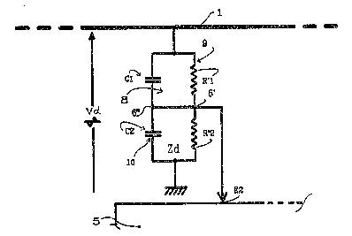
Figure 2 is a measuring bridge according to the invention and
which can be used in an insulation monitor input circuit similar
to the one illustrated in figure 1.
DESCRIPTION OF THE PREFERRED EMBODIMENT
.
Figure 2 shows the line wire 1 of the DC electrical mains
system, for example a 600 volt system, whose insulation
impedance is to be determined, according to the manner of the

2~.'5i8~
device in figure 1, by means of the reference AC voltage Vd, for
example with a frequency of 4 Hertz and a peak-to-peak amplitude
of 30 volts, which is input to the DC mains system, and of the
processing unit S whose input circuit comprises a device for
measuring the current Id flowing in the insulation impedance Zd
(see figure 1), and the device for measuring the reference
voltage Vd which is the subject of the present invention, and
which is therefore represented on its own in flgure 2.
The device for measuring the voltage Vd here comprises a mixed
bridge 8 which is formed by paxallel connection with joining of
the two respective potentiometric output points 6' and 6" :
- of a resistive dividing bridge 9 which is made up, for
example, of a resistance R'l of about 100 Megaohms and of a
resistance R'2 of about 100 kiloohms, so that the -total
imped~nce (R ' 1 + R ' 2 ) of the bridge is vexy high with respect to
the input impedance of the DC mains system, which is itself
generally about 1 to 2 Megaohms, whereas the dividing ratio is
very low, about one thousandth,
- of a capacitive dividing bridge 10 which is made up of two
electrochemical capacitors Cl and C2 of high capacity, the
latter being sufficient for the impedance of each of the
capacitors Cl and C2, at the 4 Hertz frequency of the reference
voltage Vd, to be very low with respect to that of the weaker,
R'2, of the resistances of the resistive dividing bridge 9; th~
capacities are moreover chosen to give the bridge 10 a high
dividing ratio. In the example, identical capacitors of 10
microfarads are used, so that their impedance is about 4 kilo-
ohms at the 4 Hertz frequency (therefore negligible with respect
to the resistance R' 2 which has a value of 10 kiloohms) and the
transformer ratio of the capacitive dividing bridge 10 is one
half.

2~ 8~
Operation of the measuring circuit 8 is as follows :
For the direct current present on the line wire l, the
capacitive bridge 10 does not have any influence, and, as the
potentiometric dividing ratio of the resistive bridge 9 is one
thousandth, the DC voltage input at the point E2 to the
processing ur,it 5 is only 0.6 volts, therefore very low.
As far as the reference voltage at 4 Hertz frequency is
~oncerned, the resistances, respectively R'l and R'2, which are
connected in parallel to the capacitors Cl and C2, are much too
high to have an influence with respect to the capacitance of
each of the capacitors, which is about 4 kiloohms. The AC
voltage Vd therefore only "sees" the capacitive dividing bridge,
whose total impedance is low and whose dividing ratio (one half)
is high. The AC voltage input at the point E2 is therefore high,
about 15 volts peak-to-peak, and is much higher than the
previously mentioned value of 0.6 volts of the DC voltage input
at the point E2, whereas the alternating current input is also
high due to the low total impedance (about 8 kiloohms~ of the
bridge.
The invention is not limited to the embodiment particularly
described herein, and any other kind of mixed bridge equivalent
to the bridge 8 of figure 2 could be used in order to implement
it.

Dessin représentatif
Une figure unique qui représente un dessin illustrant l'invention.
États administratifs

2024-08-01 : Dans le cadre de la transition vers les Brevets de nouvelle génération (BNG), la base de données sur les brevets canadiens (BDBC) contient désormais un Historique d'événement plus détaillé, qui reproduit le Journal des événements de notre nouvelle solution interne.

Veuillez noter que les événements débutant par « Inactive : » se réfèrent à des événements qui ne sont plus utilisés dans notre nouvelle solution interne.

Pour une meilleure compréhension de l'état de la demande ou brevet qui figure sur cette page, la rubrique Mise en garde , et les descriptions de Brevet , Historique d'événement , Taxes périodiques et Historique des paiements devraient être consultées.

Historique d'événement

Description Date
Inactive : CIB expirée 2020-01-01
Inactive : CIB de MCD 2006-03-11
Le délai pour l'annulation est expiré 2000-12-27
Demande non rétablie avant l'échéance 2000-12-27
Réputée abandonnée - omission de répondre à un avis sur les taxes pour le maintien en état 1999-12-23
Lettre envoyée 1998-12-03
Inactive : Renseign. sur l'état - Complets dès date d'ent. journ. 1998-12-03
Inactive : Dem. traitée sur TS dès date d'ent. journal 1998-12-03
Exigences pour une requête d'examen - jugée conforme 1998-11-18
Toutes les exigences pour l'examen - jugée conforme 1998-11-18
Demande publiée (accessible au public) 1992-06-27

Historique d'abandonnement

Date d'abandonnement Raison Date de rétablissement
1999-12-23

Taxes périodiques

Le dernier paiement a été reçu le 1998-11-23

Avis : Si le paiement en totalité n'a pas été reçu au plus tard à la date indiquée, une taxe supplémentaire peut être imposée, soit une des taxes suivantes :

  • taxe de rétablissement ;
  • taxe pour paiement en souffrance ; ou
  • taxe additionnelle pour le renversement d'une péremption réputée.

Les taxes sur les brevets sont ajustées au 1er janvier de chaque année. Les montants ci-dessus sont les montants actuels s'ils sont reçus au plus tard le 31 décembre de l'année en cours.
Veuillez vous référer à la page web des taxes sur les brevets de l'OPIC pour voir tous les montants actuels des taxes.

Historique des taxes

Type de taxes Anniversaire Échéance Date payée
TM (demande, 6e anniv.) - générale 06 1997-12-23 1997-11-20
Requête d'examen - générale 1998-11-18
TM (demande, 7e anniv.) - générale 07 1998-12-23 1998-11-23
Titulaires au dossier

Les titulaires actuels et antérieures au dossier sont affichés en ordre alphabétique.

Titulaires actuels au dossier
MERLIN GERIN
Titulaires antérieures au dossier
CHRISTIAN PELLEGRIN
LUC WEYNACHTER
PATRICE ALLIN
Les propriétaires antérieurs qui ne figurent pas dans la liste des « Propriétaires au dossier » apparaîtront dans d'autres documents au dossier.
Documents

Pour visionner les fichiers sélectionnés, entrer le code reCAPTCHA :


Pour visualiser une image, cliquer sur un lien dans la colonne description du document (Temporairement non-disponible). Pour télécharger l'image (les images), cliquer l'une ou plusieurs cases à cocher dans la première colonne et ensuite cliquer sur le bouton "Télécharger sélection en format PDF (archive Zip)" ou le bouton "Télécharger sélection (en un fichier PDF fusionné)".

Liste des documents de brevet publiés et non publiés sur la BDBC .

Si vous avez des difficultés à accéder au contenu, veuillez communiquer avec le Centre de services à la clientèle au 1-866-997-1936, ou envoyer un courriel au Centre de service à la clientèle de l'OPIC.

({010=Tous les documents, 020=Au moment du dépôt, 030=Au moment de la mise à la disponibilité du public, 040=À la délivrance, 050=Examen, 060=Correspondance reçue, 070=Divers, 080=Correspondance envoyée, 090=Paiement})


Description du
Document 
Date
(aaaa-mm-jj) 
Nombre de pages   Taille de l'image (Ko) 
Dessin représentatif 1999-07-21 1 9
Abrégé 1995-07-09 1 16
Dessins 1995-07-09 1 21
Revendications 1995-07-09 2 46
Description 1995-07-09 6 217
Rappel - requête d'examen 1998-08-24 1 129
Accusé de réception de la requête d'examen 1998-12-02 1 177
Courtoisie - Lettre d'abandon (taxe de maintien en état) 2000-01-19 1 185
Taxes 1996-11-24 1 67
Taxes 1995-11-21 1 61
Taxes 1994-11-22 2 111
Taxes 1993-11-25 1 42