Sélection de la langue

Search

Sommaire du brevet 2058691 

Énoncé de désistement de responsabilité concernant l'information provenant de tiers

Une partie des informations de ce site Web a été fournie par des sources externes. Le gouvernement du Canada n'assume aucune responsabilité concernant la précision, l'actualité ou la fiabilité des informations fournies par les sources externes. Les utilisateurs qui désirent employer cette information devraient consulter directement la source des informations. Le contenu fourni par les sources externes n'est pas assujetti aux exigences sur les langues officielles, la protection des renseignements personnels et l'accessibilité.

Disponibilité de l'Abrégé et des Revendications

L'apparition de différences dans le texte et l'image des Revendications et de l'Abrégé dépend du moment auquel le document est publié. Les textes des Revendications et de l'Abrégé sont affichés :

  • lorsque la demande peut être examinée par le public;
  • lorsque le brevet est émis (délivrance).
(12) Demande de brevet: (11) CA 2058691
(54) Titre français: REDRESSEUR DE RUBANS, PARTICULIEREMENT DE RUBANS METALLIQUES
(54) Titre anglais: ARRANGEMENT FOR STRAIGHTENING STRIPS, PARTICULARY METAL STRIPS
Statut: Réputée abandonnée et au-delà du délai pour le rétablissement - en attente de la réponse à l’avis de communication rejetée
Données bibliographiques
(51) Classification internationale des brevets (CIB):
  • B21C 19/00 (2006.01)
  • B21B 01/22 (2006.01)
  • B21B 01/36 (2006.01)
  • B21B 15/00 (2006.01)
  • B21B 38/06 (2006.01)
  • B21C 47/04 (2006.01)
  • B21C 47/26 (2006.01)
  • B21D 01/05 (2006.01)
  • B21D 03/05 (2006.01)
(72) Inventeurs :
  • NOE, OSKAR (Allemagne)
(73) Titulaires :
  • BWG BERGWERK- UND WALZWERK-MASCHINENBAU GMBH
(71) Demandeurs :
  • BWG BERGWERK- UND WALZWERK-MASCHINENBAU GMBH (Allemagne)
(74) Agent: BORDEN LADNER GERVAIS LLP
(74) Co-agent:
(45) Délivré:
(22) Date de dépôt: 1992-01-02
(41) Mise à la disponibilité du public: 1992-08-09
Licence disponible: S.O.
Cédé au domaine public: S.O.
(25) Langue des documents déposés: Anglais

Traité de coopération en matière de brevets (PCT): Non

(30) Données de priorité de la demande:
Numéro de la demande Pays / territoire Date
P 41 03 804.5-14 (Allemagne) 1991-02-08

Abrégés

Abrégé anglais


ABSTRACT OF THE DISCLOSURE
An arrangement for straightening finite strips,
particularly metal strips. The arrangement includes a
coiling reel, an uncoiling reel and a stretch-bending unit
arranged between the two reels. A driver each is arranged in
strip travel direction in front of and following the stretch-
bending unit. In another embodiment, a temper pass stand is
arranged in strip travel direction in front of the stretch-
bending unit and a driver is arranged following the stretch-
bending unit.
11

Revendications

Note : Les revendications sont présentées dans la langue officielle dans laquelle elles ont été soumises.


THE EMBODIMENTS OF THE INVENTION IN WHICH AN EXCLUSIVE
PROPERTY OR PRIVILEGE IS CLAIMED ARE DEFINED AS FOLLOWS:
1. In a straightening arrangement for finite strips,
particularly metal strips, the arrangement including a
coiling reel, an uncoiling reel and a stretch-bending unit
arranged between the two reels, the strips traveling in the
arrangement in a strip travel direction, the improvement
comprising a driver being arranged in strip travel direction
in front of the stretch-bending unit and a driver being
arranged in strip travel direction following the stretch-
bending unit.
2. The straightening arrangement according to claim 1,
wherein the driver arranged in strip travel direction in
front of the stretch-bending unit includes a tension
measuring device for controlling the tension of the driver.
3. The straightening arrangement according to claim 2,
wherein the tension measuring device is a tension measuring
roller.
4. In a straightening arrangement for finite strips,
particularly metal strips, the arrangement including a
coiling reel, an uncoiling reel and a stretch-bending unit
arranged between the two reels, the strips traveling in the
arrangement in a strip travel direction, the improvement
comprising a temper roll stand being arranged in strip

travel direction in front of the stretch-bending unit and a
driver being arranged in strip travel direction following the
stretch-bending unit.
5. The straightening arrangement according to claim 4,
wherein the temper-pass stand includes a tension measuring
device for controlling the tension of the temper-pass stand.
6. The straightening arrangement according to claim 5,
wherein the tension measuring device is a tension measuring
roller.

Description

Note : Les descriptions sont présentées dans la langue officielle dans laquelle elles ont été soumises.

2 ~ ?J ~
~ACKGROUND OF T~E INVENTION
l. Field of the Invention
The present invention relates to an arrangement for
straightening finite strips, particularly metal strips. The
arrangement includes a coiling reel, an uncoiling reel and a
stretch-bending unit arranged between the two reels.
2. Description of the Related Art
In discontinuous strip treatment lines, such as, for
example, stretch-bending straightening lines, stretch-bending
straightening/temper-rolling lines, or the like, in which
only individual coils are treated, strip losses of
approximately 15 to 20 meters occur at both ends of the strip
being treated. These strip losses result particularly from
the sets of brake drums and sets of tension drums which are
usually used in known straightening arrangements and which
produce the relatively high tensions required for the
stretch-bending range. These tensions can only be build up
if the coiling reel and the uncoiling reel produce the
forward tension and the rearward tension for the sets of
tension drums.
The process of stretch-bending straightening is to be
understood as an alternating bending under high strip

~ 3
tension. Depending on the strip dimensions and the yield
point of, for example, steel strips having thicknesses of
1.0 - 4.0 mm and a width of 1500 mm, the tension for stretch-
bending straightening is approximately 8 - 20 tons. Such a
tension cannot be produced by the coiling and uncoiling reels
because the usual specific coiling tension is 10 - 15 N/mm2.
A particular problem is the non-straightened strip beginning
which must be wound into the coil and can only be cut off by
the final user of the strip.
Another disadvantage is to be seen in the fact that the
respective strip beginning must be newly introduced into the
sets of tension drums. This results in substantial time and
production losses. Moreover, thick strips can only be
introduced by means of a so called pilot strip or a rope.
SUMMARY OF THE INVENTION
Therefore, it is the object of the present invention to
provide a straightening arrangement for finite strips,
particularly metal strips, of the above-described type, which
makes it possible in a simple manner, without time-consuming
introduction of the strip and large strip losses,~to coil
strips in a discontinuous strip line and to straighten the
strip or to straighten and temper-roll the strip.

2 ~
In accordance with the present invention, the above-
object is met by arranging in strip travel direction before
and following the stretch-bending unit a driver each or a
temper-pass stand and a driver.
~ ccordingly, the present invention provides that the
stretch-bending unit is arranged between two drivers or
between a driver and a temper-pass stand and, in turn, the
two drivers or the driver and the temper-pass stand are
arranged between the coiling reels and the stretch-bending
unit.
The present invention starts from the finding that the
driver arranged in strip travel direction behind the stretch-
bending unit can be driven as a tension driver and the driver
or temper-pass stand arranged in strip travel direction in
front of the stretch-bending unit can be used as a brake
driver or braking temper-pass stand, respectively, such that,
instead of the usually used sets of tension drums and brake
drums, only these drivers or the driver and temper-pass stand
are required for producing the high tensions required for
stretch-bending straightening. In other words, the usually
used sets of tension drums and brake drums are replaced by
the drivers for the driver and the temper-pass stand.
Moreover, this makes it also possible to produce the high
tensions in the stretch-bending range independently of the
fact whether the coiling tensions have already been built up

~ fi
or not. At any rate, the required high tensions can be
produced merely by the adjustable contact pressure force of
the driven driver rolls or rolls of the temper-pass stand.
The drivers and, if applicable, the temper-pass stand reduce
the strip losses which usually occur in sets of tension drums
at the strip beginning and the strip end because these strip
losses are reduced to the portion which is without treatment
between the tension driver and the stretch-bending unit or
the stretch-bending unit and the brake driver or temper-pass
stand. In addition, the strip to be treated can be easily
introduced into the arrangement by means of the driver or the
temper-pass stand and the stretch-bending rolls which are
adjustably mounted in the stretch-bending unit, so that
significant time and reduction losses no longer occur.
Since, furthermore, the requirements with respect to the
planeness of the strips and particularly metal strips have
increased, the straightening arrangement according to the
present invel1tion makes it possible with simple means, and
without time-consuming introduction and great strip losses,
to coil, straighten or straighten and temper-roll strips and
particularly metal strips in a continuous strip line.
In accordance with another proposal according to the
present invention, the driver or temper-pass stand arranged
in strip travel direction in front of the stretch-bending
unit includes a tension measuring device, for example, a
tension measuring roller for controlling the tension of the

2~3~s~3~
driver or of the temper-pass stand. This tension measuring
device ~s used for controlling with respect to tension the
drive of the brake driver or the temper-pass stand. As a
result, the adjusted straightening effect remains constant,
even if the coil tensioning means of the coiling reels are
switched on or off. The tension driver, on the other hand,
is the speed master of the strip line. The drive shafts of
the driver and of the temper-pass stand are driven
individually by separate drive motors.
The various features of novelty which characterize the
invention are pointed out with particularity in the claims
annexed to and forming a part of this disclosure. For a
better understanding of the invention, its operating
advantages attained by its use, reference should be had to
the drawing and descriptive matter in which there are
illustrated and described preferred embodiments of the
invention.
BRIEF DESCRIPTION OF THE DRAWING
In the drawing:
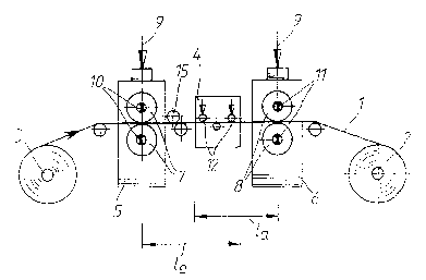
Fig. 1 is a schematic side view of a straightening
arrangement according to the present invention with two
drivers; and

~ J
Fig. 2 is a schematic side view of the straightening
arrangement according to the present invention with a driver
and a temper-pass stand.
DESCRIPTION OF THE PREFERRED EMBODIMENTS
Figs. 1 and 2 of the drawing each show an arrangement
for straightening finite strips 1, particularly metal strips
or discontinuously operating strip lines. The arrangement
essentially includes a coiling reel 2, an uncoiling reel 3
and a stretch-bending unit ~ arranged between the two reels
2, 3.
AS illustrated in Fig. 1, a driver 5, 6 each is arranged
in travel direction of the strip in front of and following
the stretch-~ending unit 4. In other words, the stretch-
bending unit 4 is arranged between two drivers 5, 6 and the
two drivers 5, 6 between the two reels 2, 3. The contact
pressure force of the driver rolls 7, 8 is adjustable in
order to produce the necessary strip tensions. The adjusting
device g is only schematically shown. The drive shafts lo,
11 of the driver rolls 7, 8 are individually'driven by drive
motors, not shown. The strip 1 is introduced by means of the
drivers 5, 6 and by means of adjustable stretch-bendlng rolls
12 of the stretch-bending unit 4.

Fig. 2 of the drawing shows a straightening arrangement
~hich operates as a stretch-bending straightening and temper-
pass line and in which, instead of a driver, a temper-pass
stand 13 with driven back-up rolls 14 is arranged in strip
travel direction in front of the stretch-bending unit 4. In
accordance with the proposal of the invention shown in Fig.
2, already existing temper-pass stands, i.e., two-high or
our-high stands, can be converted into a combined stretch-
bending and temper-rolling arrangement by providing a driver
6 and a stretch-bending straightening unit 4.
In both embodiments of the present invention, a tension
measuring device 15 is provided for the driver 5 or the
temper-pass stand 13 arranged in strip travel direction in
front of the stretch bending unit 4. The tension measuring
device 15 is, for example, a tension measuring roller and
serves for controlling the tension of the driver 5 or of the
temper roll stand 13. In both cases, the strip losses are
indicated by reference characters la at the strip beginning
and le at the strip end. The strip ~ravel direction is
indicated by an arrow.
While specific embodiments of the invention have been
shown and described in detail to illustrate the inventive
principles, it will be understood that the invention may be
embodied otherwise without departing from such principles.

Dessin représentatif
Une figure unique qui représente un dessin illustrant l'invention.
États administratifs

2024-08-01 : Dans le cadre de la transition vers les Brevets de nouvelle génération (BNG), la base de données sur les brevets canadiens (BDBC) contient désormais un Historique d'événement plus détaillé, qui reproduit le Journal des événements de notre nouvelle solution interne.

Veuillez noter que les événements débutant par « Inactive : » se réfèrent à des événements qui ne sont plus utilisés dans notre nouvelle solution interne.

Pour une meilleure compréhension de l'état de la demande ou brevet qui figure sur cette page, la rubrique Mise en garde , et les descriptions de Brevet , Historique d'événement , Taxes périodiques et Historique des paiements devraient être consultées.

Historique d'événement

Description Date
Inactive : CIB de MCD 2006-03-11
Le délai pour l'annulation est expiré 2000-01-04
Demande non rétablie avant l'échéance 2000-01-04
Réputée abandonnée - omission de répondre à un avis sur les taxes pour le maintien en état 1999-01-04
Inactive : Abandon.-RE+surtaxe impayées-Corr envoyée 1999-01-04
Demande publiée (accessible au public) 1992-08-09

Historique d'abandonnement

Date d'abandonnement Raison Date de rétablissement
1999-01-04

Taxes périodiques

Le dernier paiement a été reçu le 1997-12-01

Avis : Si le paiement en totalité n'a pas été reçu au plus tard à la date indiquée, une taxe supplémentaire peut être imposée, soit une des taxes suivantes :

  • taxe de rétablissement ;
  • taxe pour paiement en souffrance ; ou
  • taxe additionnelle pour le renversement d'une péremption réputée.

Les taxes sur les brevets sont ajustées au 1er janvier de chaque année. Les montants ci-dessus sont les montants actuels s'ils sont reçus au plus tard le 31 décembre de l'année en cours.
Veuillez vous référer à la page web des taxes sur les brevets de l'OPIC pour voir tous les montants actuels des taxes.

Historique des taxes

Type de taxes Anniversaire Échéance Date payée
TM (demande, 6e anniv.) - générale 06 1998-01-02 1997-12-01
Titulaires au dossier

Les titulaires actuels et antérieures au dossier sont affichés en ordre alphabétique.

Titulaires actuels au dossier
BWG BERGWERK- UND WALZWERK-MASCHINENBAU GMBH
Titulaires antérieures au dossier
OSKAR NOE
Les propriétaires antérieurs qui ne figurent pas dans la liste des « Propriétaires au dossier » apparaîtront dans d'autres documents au dossier.
Documents

Pour visionner les fichiers sélectionnés, entrer le code reCAPTCHA :


Pour visualiser une image, cliquer sur un lien dans la colonne description du document. Pour télécharger l'image (les images), cliquer l'une ou plusieurs cases à cocher dans la première colonne et ensuite cliquer sur le bouton "Télécharger sélection en format PDF (archive Zip)" ou le bouton "Télécharger sélection (en un fichier PDF fusionné)".

Liste des documents de brevet publiés et non publiés sur la BDBC .

Si vous avez des difficultés à accéder au contenu, veuillez communiquer avec le Centre de services à la clientèle au 1-866-997-1936, ou envoyer un courriel au Centre de service à la clientèle de l'OPIC.


Description du
Document 
Date
(aaaa-mm-jj) 
Nombre de pages   Taille de l'image (Ko) 
Revendications 1992-08-08 2 38
Abrégé 1992-08-08 1 12
Dessins 1992-08-08 2 25
Description 1992-08-08 7 192
Dessin représentatif 1999-04-22 1 8
Rappel - requête d'examen 1998-09-02 1 129
Courtoisie - Lettre d'abandon (taxe de maintien en état) 1999-01-31 1 184
Courtoisie - Lettre d'abandon (requête d'examen) 1999-02-14 1 171
Taxes 1996-11-20 1 47
Taxes 1995-09-26 1 38
Taxes 1994-11-01 1 58
Taxes 1993-10-20 1 30