Note : Les descriptions sont présentées dans la langue officielle dans laquelle elles ont été soumises.
-1- 2~ 3
FLEXIBLE CORD WITH HIGH MODULUS
ORGANIC FIBER STRENGTH MEMBER
The invention relates in general to a
reinforced electrically conductive cable and ~n
particular to an electrical cable having a single yarn
high modulus or~anic fiber strength ~ember surrounded
by metal conductors.
Conventional electrical cables of the type
used in household electric cord set6 are manufactured
from stranded copper wire surrounded by a filler
material, such as paper, ~ute, cotton or rayon. The
filler material reduces the amount of jacket material
required for the cord and is typically helically
wrapped about the ctranded copper conductors. An
insulator, such as a polyYinylchloride jacket, is
extruded over the filler material to complete the cord.
Unfortunately those household cord sets
suffer from several drawbacks. At present, there is a
requirement that household electric cord sets have
sufficient tensile strength to withstand a tensile
force of 170 pounds. The pri~ary strength providing
members in prior art cord sets are the conductors and
the filler ~aterial within the cord set, which may fail
under the ~tress of such a force.
In addition, it has become relatively
expensive to manufacture cord sets using paper and jute
fillers. The paper and jute fillers are meant to
occupy volume, as well as provide tensile strength
within the cable, ~o that for a given outside diameter
of a cable jacket less polyvinylchloride insulation is
required, thereby saving money. It is often necessary
for an electric plug or connector to be attached to the
cord. As a result, the outer layer of
polyvinylchloride insulation must be removed completely
without nicking or damaging the copper wire conductor
C~f3}~ ~/?~
-2-
strands and causing a loss of conductiYity which may
result in an increase in the resistivity of the wire.
Such an unwanted increase in resistivity may cause the
wire to overheat when it i~ connected to a low
impedance electrical load. As a result, it is
necessary to remo~e the insulating polyvinylchloride
layer manually, after which the jute or paper filling
is removed manually. Attempts to automate the
labor-intensive insulation stripping process have met
with little success because complete removal of the
insulation and filler often results ln damage to the
underlying conductors.
Cords with multiple insulated leads
conventionally have an outer jacket of
polyvinylchloride, which holds the leads together and
provides additional protection against damage. To
achieve a ~iven overall cord thickness and fill the
grooves between leads, paper or jute fillers are
bundled with the inner leads and a polyvinylchloride
jacket is extruded around the bundle, thereby reducing
the amount of polyvinylchloride used. These fillers
result in the same obstacles to automated stripping as
mentioned above.
In addition, such ~illers do not have the
flexibility that polyvinylchloride has, and so add to
the stiffness of the cord. To retain maximum
flexibility, the grooves between leads would have to be
filled with polyvinylchloride, which would make the
cable unnecessarily heavy.
Co-axial cords are known which contain
organic foam. However, because the purpose of the foam
is to improve electrical transmission through the
dielectric properties of the foam, the foam is extruded
in contact with the conductive metal of the cord. The
foam i~ not used as a filler material between two non-
porous, ~nsulating jackets, as paper or jute are used
as mentioned above.
-3- 2 ~ ) J . l3
What 16 needed, then, i8 an improved
electrical cable or cord strong enough to withstand a
tensile force of 170 pounds or more, requiring a
minimum of polyvinylchloride, retaining maximal
flexibility and minimal weight, and which may be
~tripped of insulation quickly and easily in order to
expose the copper conductors for connection to plug
assemblies, connectors and the like.
An electrical cable embodying the present
invention has a single yarn tensile ~trength member.
plurality of fine copper strands ~re helically wound
about the single yarn tensile strength member and in
contact with it. A polyvinylchloride insulated jacket
is extruded over the copper 6trands. A
polyvinylchloride foam filler layer may be extruded
over a plurality of such insulated cables, and a non-
porous polyvinylchloride jacket extruded over the foam
filler layer.
It is a principal aspect of the present
invention to provide a high strength electric cord or
cable for household use.
It is another aspect of the present invention
to provide an electrical cable from which the
insulation easily may be stripped by automated
equipment without damaging the conductors thereof.
It is yet another aspect of the present
invention to provide an electrical cable with multiple
leads inside an outer iacket of maximal flexibility and
minimal weight which easily may be stripped by
automated equipment.
Other aspects of the present invention will
become obvious to one skilled in the art upon a perusal
of the specific~tion and the claims in light in the
accompanying drawings.
-4~ 7 ~ '~
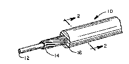
FIG. 1 i~ an isometric view of an electrical
cable embodying the present invention;
FIG. 2 i~ a ~ection taken 6ubstantially along
line 2--2 of FIG. 1 showing detail~ of the internal
arrangement of the electrical cable;
FIG. 3 is an isometric view of an alternate
embodiment of the electrical cable;
FIG. 4 i~ a 6ection taken substantially along
line 4--4 of FIG. 3 showing detail~ of the internal
arrangement of the electrical cable:
FIG. 5 is an i60metric view of another
alternate embodiment of the electrical cable;
FIG. 6 is a section taken substantially along
line 6--6 of FIG. 5 showing details of the internal
organization of the electrical cable;
FIG. 7 is an isometric view of the cable of
FIG. 6 positioned proximately with a pair of cutters,
portions of which are shown;
FIG. 8 is an elevational view, partially in
section, of the cable of FIG. 7 with the cutters
engaging it;
FIG. 9 is an end view of the cable and
cutters of FIG. 8;
FIG. 10 is an elevational view, partially in
section, of the cable of FIG. 8 showing an outer ~acket
being stripped off by the cutters:
FIG. 11 is an isometric view of the cable of
FIGS. 1 and 2 positioned proximately with a pair of
cutters, portions of which are 6hown;
FIG. 12 is an elevational view, partially in
section, of the cable of FIG. 11 with the cutters
engaging it;
FIG. 13 is an end view of the cable and
cutters of FIG. 12;
FIG. 14 is an elevational view, partially in
2 f~
section, of the cable of FIG. 12 ~howing a jacket being
stripped off by the cutters.
FIG. 15 is an lsometric view of yet another
alternate embodiment of the ~lectrical cable;
FIG. 16 is a section taken suhstantially
along line 6--6 of FIG. 15 showing detail of the
internal organization of the electrical cable
FIG. 17 is an isometric view of the cable of
FIG. 16 positioned proximately with a pair of cutters,
portions of which are shown;
FIG. 18 is an elevational view, partially in
section, of the cable of FIG. 17 with the cutters
engaging it;
FIG. 19 is an end view of the cable and
cutters of FIG. 1~;
and,
FIG. 20 is an elevational view, partially in
section, of the cable of FIG. 18 ~howing an outer
jacket being stripped off by the cutters;
Referring now to the drawings and especially
to FIGS. 1 and 2, an electrical cable or flexible cord
embodying the present invention and generally
identified by numeral 10 is shown therein. The
electrical cable 10 includes a single yarn, centrally
located, circular cross section tensile strength
member 12. The strength member 12 is comprised of a
multi-filament 1500 denier polyamide yarn, coated with
polyurethane, having a high modulus and of the type
~old under the designation Kevlar 29 or alternatively,
Kevlar 49. The yarn has a diameter of 0.010-0.015
inches. A coating of polyurethane covers the polyamide
yarn in order to prevent it from fraying.
Alternatively, nylon, varnish or epoxy coating could be
-6~
used to prevent fraying of the polyamide yarn. It
should be appreciated that the polyurethane fray
resisting coating also meets Underwriters Laboratories
90C. temperature standards. A plurality of c~pper
~trands 14 is wound helically about the slngle yarn
~trength member 12. The plurality o~ copper strands 14
comprises between 41 ~nd 65 strands in the present
embodiment. Each of the Rtrands 14 has a circular
cross section. It may be appreciated that the
strands 14 are wound about the single yarn stren7th
member 12 without any intermediate filler or layered
material such as paper, jute, and the like being
interposed in between. The plurality of strands 14
contacts and substantially completely covers the single
yarn strength member 12. Each of the strands 14 has a
diameter in the range of Q.0050 inches or greater. In
some embodiments of the present invention each of the
copper strands may have a diameter of .010 inches. For
such a strand diameter, only cixteen copper strands
2V would typically comprise the plurality. A
polyvinylchloride insulating jacket 16, having a
circular cross section, i5 extruded over the plurality
of copper strands 14 to 6ubstantially completely cover
and enclose them.
Referring now to FIGS. 3 and 4, an
alternative electrical cable 30 is shown therein. The
electrical cable 30 includes a single yarn high modulus
polyamide tensile strength member 32 having a
6ubstantially circular cross section. The polyamide
3~ strength member 32 is composed of Kevlar 29 or
Kevlar 49 and has a diameter of 0.010-0.015 inches. A
plurality of copper conductor strands 34 is helically
wound about each other and located adjacent to the
6trength member 32. The copper conductor strands 34
are each 0.0050 inches or greater in diameter. In the
present embodiment, be~ween 41 and 65 strands are
employed. A polyvinylchloride jacket 36 is extruded
~ !;
-7-
over the strength me~ber 32 and the conductor
strands 34.
In a ~till further embodiment, as may be~t be
seen in FIGS. 5 and 6, a multiple-lead cable 50 has a
plurality of high 6trength cords 52, 54, and 56. Each
of the cords 52, 54, and 56 is substantially identical
to the cable lo s~own in FIGS. 1 and 2 and described
above. The cord 52 has an inner polyvinylchloride
~acket 60 which is extruded over a single yarn
polyamide tensile strength member 62 coated with
polyurethans and a plurality of copper conductor
strands 64 are disposed ~elically about and in contact
with the strength member 62. The cord 5~ has an inner
polyvinylchloride jacket 70 ~urrounding and contacting
a plurality of helically wound copper conductor
strands 72. A ~ingle yarn polyamide tensile strength
me~ber 74 is coated with polyurethane and completely
surrounded by and in contact with the copper conductor
strands 72. The cord 56 has an inner polyvinylchloride
jacket 80 having a plurality of copper conductor
~trands 82 helically wound inside thereof with a ~ingle
yarn polyamide tensile strength member 84 coated with
polyurethane and completely ~urrounded by and in
contact with the plurality of copper conductors 82. An
outer polyvinylchloride jacket 86 surrounds and
contacts the inner jacket6 60, 70 and 80. The outer
polyvinylchloride jacket 86 is extruded over the
jackets 60, 70 and 80.
In a still further embodiment, as may best be
seen in FIGS. 15 and 16 a foam-skin composite jacket
multiple-lead cable 150 has a plurality of high
strength cords 1S2, 154, and 156. Each of the cords
152, 154, and 156 ~s substantially identical to the
cable 10 shown in FIGS. 1 and 2 and described above.
The cord 152 has an inner polyvinylchloride jacket 160
which is extruded over a single yarn polyamide tensile
strength member 162 coated with polyurethane and a
~,~r~
-8-
plurality of co~er conductor strands 164 are disposed
helically about and in contact with the strenqth
member 162. The cord 154 has an inner
polyvinylchloride ~acket 170 ~urrounding and contacting
a plurality of helically wound copper conductor
strands 172. A ~ingle y3rn polyamide tensile ~trength
member 174 is co~ted with polyurethane and completely
surrounded by and in contact with the copper conductor
strands 172. The cord 156 has an inner
polyvinylchloride ~acket 180 having a plurality of
copper conductor strands 182 helically wound inside
thereof with a ~ingle yarn polyamide tensile strength
member 184 coated with polyurethane and completely
6urrounded by and in contact with the plurality of
copper conductors 182. A polyvinylchloride foam filler
layer 190 surrounds and contacts the inner jackets 160,
170, and 180. The polyvinylchloride foam filler layer
is formed during the extrusion process by blending loO
parts polyvinylchloride with 1 part azo-dicarbonamide
2() type foaming agent at a temperature of about 200C,
which is sufficient to activate the foaming agent and
melt the polyvinylchloride but insufficient to destroy
the polymer. The foam filler layer has approximately
35~ void content. An outer polyvinylchloride jacket
200 surrounds and contacts the polyvinylchloride foam
filler layer 190. The outer polyvinylchloride jacket
200 is extruded over the foam filler layer 190. The
polyvinylchloride foam filler layer 190 can have a
thickness in the range of approximately 25-75% that oP
the thickness of the outer jacket 200.
It may be appreciated that the single yarn
strength member provides a number of advantages to the
users of the instant invention. The single yarn high
modulus tensile strength member is flexible and
provides high strength to the cord 10 allowing the cord
to exceed the 170 pound tensile ~trength requirement
set forth by Underwriters Laboratories and other
2 f ;
_g_
6tandards-making organizations.
It may also be appreciated that the flexible
cord with multiple leads surrounded by an outer jacket
of foam and a non-porou6 ~kin provides a cord that is
cheaper and lighter than a cord using Rolid
polyvinylchloride and more flexible than a cord using
paper or jute fillers. The foam filler layer uses less
polyvinylchloride than the solid polyvinylchloride
needed to fill the grooves betwee~ leads in the cord,
so is therefore cheaper to produce and lighter in
weight than an all-~olid polyvinylchloride csrd. ~he
foam filler layer is also more flexible than the same
thickness of solid polyvinylchloride or paper and jute
fillers. The outer jacket of polyvinylchloride meets
the non-porosity requirement for cable jackets as set
forth by Underwriters Laboratories and other standards-
making organizations.
Additionally, ~s may best be seen in FIGS. 11
through 14, the cable 10 may be quickly and easily
stripped. A cutter 90 having a pair of mating cutter
halves 92 and 94 may be used to strip the
polyvinylchloride jacket 16 down to the copper
~trands 14. Since there is no intermediate layer, such
as paper, jute, cotton or rayon, between the copper
conductor strands 14 and the polyvinylchloride
jacket 16, the jacket 16 need not be cut all the way
through; a thin web portion 100 may be left. The
remaining thin web portion 100 then i6 ~evered by
stretching it, while the copper conductor strands 14
and the inner ~trength member 12 remain intact. A
severed portion 102 of the jacket 16 i~ then removed by
61 iding it off the copper conductor strands 14. In
addition, the tensile ~trength member 12, since it is
located within the helically wound strands 14, is
unaffected by the ~tripping process; 60 that even when
6tripped of the outer jacket 16 down to the conductor
strands 14, the cable 10 retains its high strength.
2~ '~ i 3
--10--
The cable 30, 8hown in FIGS. 3 and 4, also
may be stripped down to the strength mem~er 32 and the
copper strands 34 and the polyvinylchloride
insulation 36 easily removed therefrom. Should it be
desired, the tensile strength member 32 may then be
separated from the conductor strands 34 to allow the
conductor strand 34 to be fitted into relatively small
connectors of the type used in electrical plugs to
which they must be electrically connected.
The multiple-lead cable 50 also may be
stripped in a similar fashion, as may best be 6een in
FIGS. 7 through 10. A pair of cutter halves 110 having
a first cutter 112 and a second cutter 114 cut through
the outer jacket 86 leaving only a thin web portion 116
intact. The outer jacket 86 is then stretched and a
severed portion 118 i6 removed from the cords 52, 54
and 56. The individual cords 52, 54 and 56 then are
6tripped in the manner set forth above.
The foam-skin composite jacket multiple-lead
cable 150 also may be stripped in a similar fashion, as
may best be seen in FIGS. 17 through 20. A pair of
cutter halves 210 having a fir~t cutter 212 and a
second cutter 214 cut through the outer jacket 200, and
cut substantially into the foam filler layer 190,
leaving a portion of the foam filler layer 216 intact.
The outer jacket 200 and the foam filler layer 190 are
then ~tretched, easily tearing the intact portion of
the foa~ filler layer 216, and a severed portion 218 is
removed from the cords 152, 154, and 156. The
individual cords 152, 154, and 156 are then stripped in
the manner set forth above.
It may be appreciated that the foam-~kin
composite jacket multiple-lead cable is significantly
easier to strip than conventional multiple-lead cables.
The foam filler layer has a lower tensile ~trength than
the ~ame thickness of either paper and jute or 601id
polyvinylchloride, therefore requiring less
2~ l 3
longitudinal force for ~tripping. The foam f$11er
layer also 6eparates from the inner leads more easily
than a ~olid polvvinylchloride outer jacket does,
because the fosm void conten~ reduces the surface area
of actual physical contact between the
polyvinylchloride of the foam and the inner leads,
thereby reducing frictional ~orces.
A particular advantage of the present
invention lies ~n the fact that a single yarn of
1~ polyamide iB used in the fabrication of the instant
invention, rather than multiple yarns which ~ust be
bundled before the helical copper strands are wound
thereabout. The single yarn of flexible polyamide
fiber avoids the neces~ity of holding multiple yarns in
proximity with each other while the multiple copper
strands are wound thereabout. Thus, it may be
appreciated that the instant invention provides a high
strength electrical cable which may be easily 6tripped
in a machine operation, but which remains flexible and
2~ easy to build.
While there has been illustrated and
described a particular embodiment of the present
invention, it will be appreciated that numerous changes
and modifications will occur to those skilled in the
art, and it is attended in the appended claims to cover
all those changes and modifications which fall within
the true spirit and scope of the present invention.